
A small eight-pin chip has been blinking LEDs, sounding alarms, stretching pulses, and delaying events since the early 1970s. It is the 555 timer, one of those rare components that is simple enough for a first breadboard project and useful enough to remain in production more than half a century after its introduction.
The familiar package hides an unusual origin story. The 555 came out of a recession, a consulting contract, an argument over product strategy, and a last-minute redesign made during a drive home. Its longevity came from one practical decision: put the essential pieces of a general-purpose timing circuit into an inexpensive standard integrated circuit, then let the user choose the timing with an external resistor and capacitor.
Much of the 555's history came from people, budgets, and timing, and less from any single clever schematic. This account follows the design from its origin at Signetics to the versions still in production today.
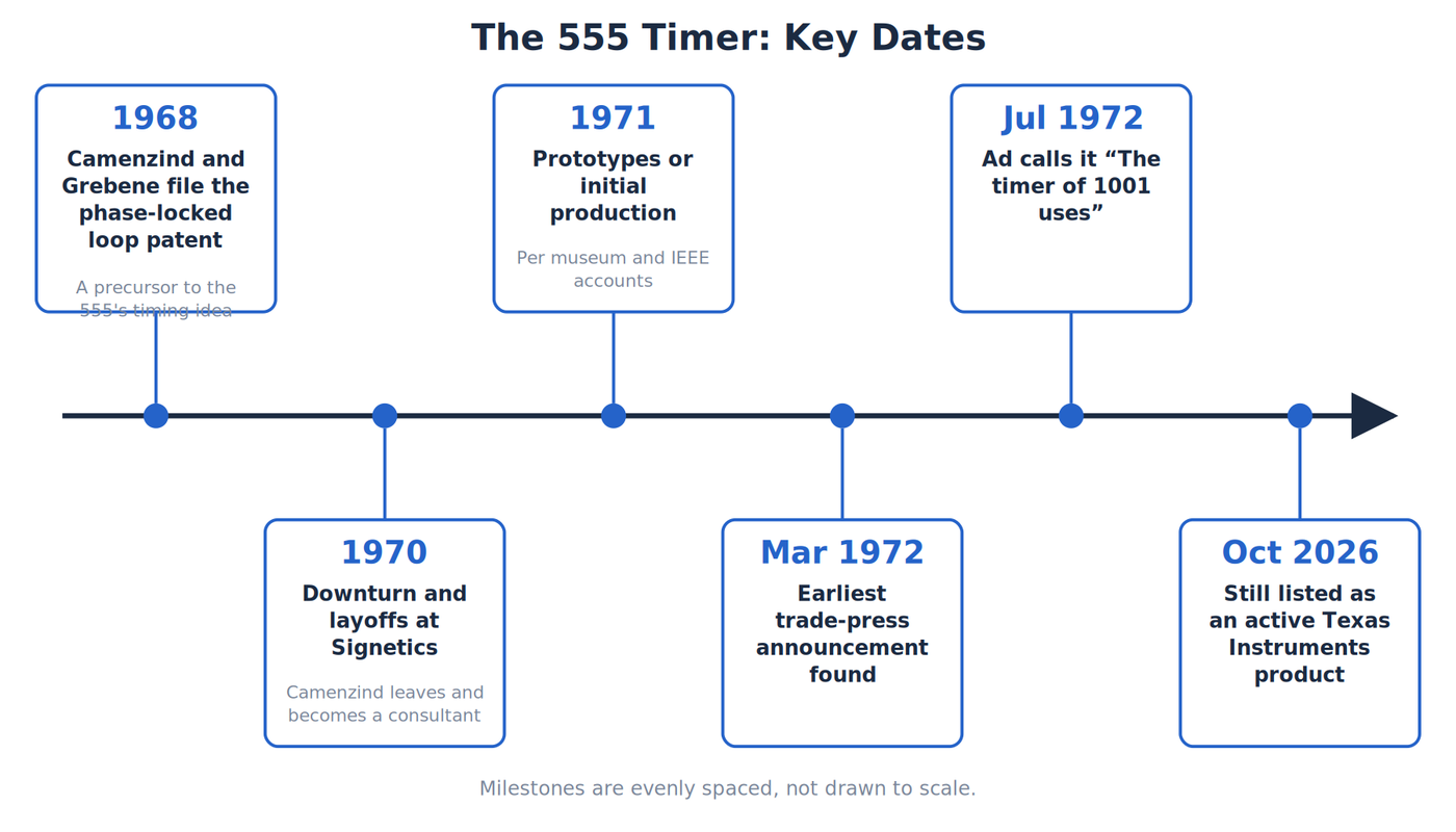
Key dates in the story of the 555 timer, from the phase-locked loop patent to today. Credit: The Makers Workbench.
A timer built during a downturn
Hans R. Camenzind joined Signetics in the late 1960s to work on linear integrated circuits. These are chips that handle continuously varying voltages rather than treating every signal as a digital one or zero. In 1970, a semiconductor downturn pushed Signetics into heavy layoffs. Camenzind left the company and later arranged a one-year consulting contract. Signetics loaned him equipment, and he rented workspace between two restaurants in Sunnyvale, California.
Camenzind recalled being paid $1,200 per month. That works out to $14,400 for the year, a modest amount even before accounting for the risk of working as an independent consultant. The assignment gave him room to pursue an idea that Signetics engineers did not immediately welcome: a dedicated timer chip.
At the time, a designer could assemble a timer from an operational amplifier, a comparator, a Zener diode, and other parts. Some people at Signetics worried that a timer would replace products the company already sold. Marketing manager Art Fury supported the project anyway. That decision gave Camenzind the opportunity to turn an arrangement of familiar circuit blocks into a new standard component.
The oscillator idea behind the timer
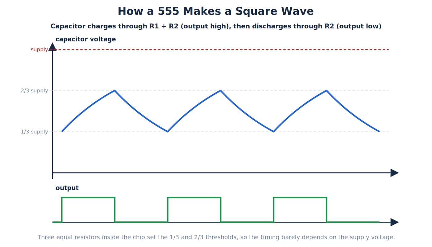
How a 555 makes a square wave: the capacitor charges through R1 and R2 while the output is high, then discharges through R2 while it is low. Credit: The Makers Workbench.
Camenzind had already worked on phase-locked loops and voltage-controlled oscillators, including the Signetics NE566. A voltage-controlled oscillator changes its frequency in response to an input voltage. That earlier work gave him a useful timing trick.
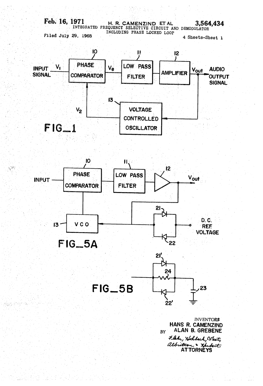
Sheet 1 of a 1971 Signetics patent for a phase-locked loop, the earlier work behind the 555 timing trick. This is not a 555 schematic. Credit: Drawing from US Patent 3,564,434 (Camenzind and Grebene, Signetics), sheet 1.
Three equal resistors connected across the power supply create reference points at one-third and two-thirds of the supply voltage. A capacitor charges and discharges between those levels. Because the charging voltage and the two reference levels all move with the supply, changes in supply voltage largely cancel out. The timing still depends mainly on the external resistance and capacitance.
The first timer design needed nine pins. That was awkward because common integrated-circuit packages offered eight or fourteen. Moving to fourteen pins would make the part larger and more expensive.
Camenzind later wrote that the nine-pin version passed its design review. On a drive home roughly two weeks later, he realized he could remove the voltage-to-current converter and charge the timing capacitor through a plain resistor. The waveform would become an exponential curve rather than a straight ramp, but the supply-cancellation idea still worked. The change reduced the circuit enough to fit an eight-pin package. He made the redesign without requesting another formal design review and told Fury, who favored the cheaper package.
What happens inside a 555
A 555 is easier to understand if you picture it as a tiny supervisor watching a capacitor.
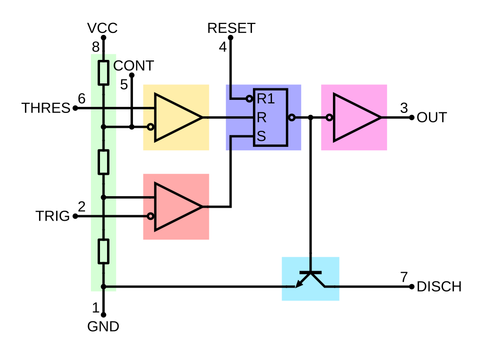
The NE555 in block form: a three-resistor divider, two comparators, a flip-flop, a discharge transistor and the output stage. Credit: BlanchardJ and Wdwd, via Wikimedia Commons. Public domain.
Inside the chip, the three-resistor divider establishes the one-third and two-thirds supply thresholds. Two comparators continually compare the capacitor voltage with those reference levels. A comparator is a circuit that reports which of two input voltages is higher. Their outputs control a flip-flop, a simple memory element that remembers which threshold was crossed most recently.
When the capacitor voltage falls below the lower threshold, the flip-flop changes state and the output goes high. When the capacitor rises above the upper threshold, the flip-flop changes back, the output goes low, and an internal discharge transistor can empty the capacitor. An output stage provides enough current to drive another logic input and, in many cases, a small load.
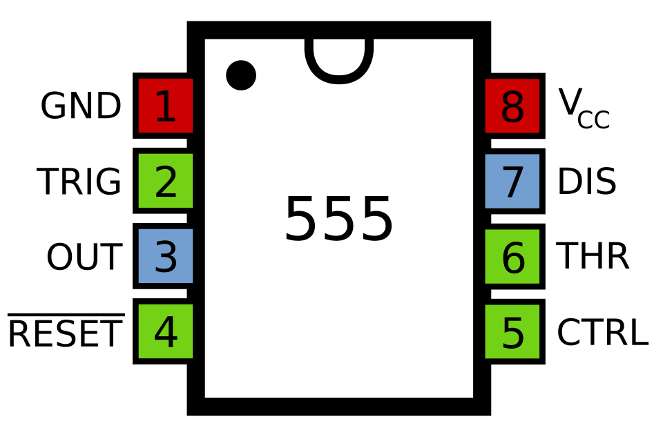
The eight pins of a 555: ground, trigger, output, reset, control, threshold, discharge and supply. Credit: Inductiveload, via Wikimedia Commons. Public domain.
That arrangement supports two classic modes. In monostable mode, an external trigger starts one timed pulse. In astable mode, the capacitor repeatedly charges and discharges, producing a continuous stream of pulses. Designers also use the control-voltage and reset pins for pulse-width modulation, missing-pulse detection, and other variations.
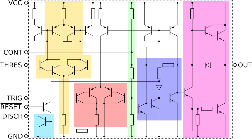
A teaching drawing of the bipolar NE555 at the transistor level. It is not a scan of a Signetics datasheet. Credit: Wdwd, via Wikimedia Commons, CC BY 3.0.
From prototype to 75-cent product
The exact border between prototype, production, and broad commercial availability is less tidy than many summaries suggest. Museum and IEEE accounts place prototypes or initial production in 1971. The earliest trade-press announcement opened for this project appeared on March 27, 1972. A Signetics advertisement dated July 3 said the timer was available off the shelf. Published timelines also record prototypes finished in October 1971 as the NE555V, in a plastic DIP, and the SE555T, in a metal TO-5 can.
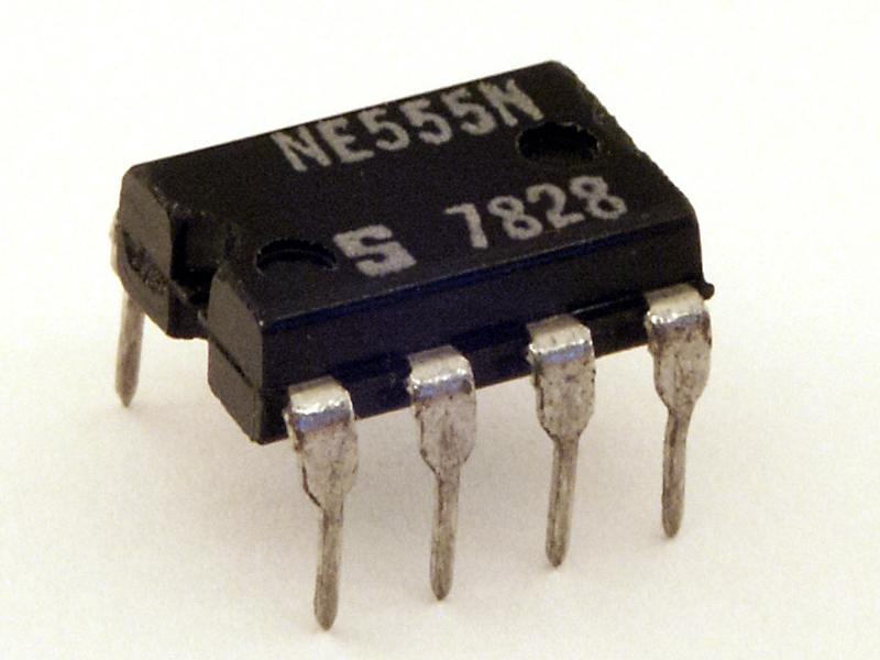
A Signetics NE555N in a plastic DIP, date-coded week 28 of 1978. Credit: Stefan506, via Wikimedia Commons, CC BY-SA 3.0. File later edited by Jahoe and JayCubby.
That commercial record supports a careful description: Camenzind designed the chip during 1970 and 1971, and Signetics brought it to the market in 1972.
Fury set the price at 75 cents in quantities of 100. Signetics promoted the device as a general-purpose timer with delays ranging from microseconds to about an hour. The low price mattered. A designer no longer had to spend several parts, extra board space, and additional assembly work on an ordinary timing function.
Signetics understood that the chip needed to be more than an inexpensive delay. Its July 1972 advertising called it “The timer of 1001 uses.” The phrase was marketing, but the underlying strategy was sound. A standard part could reach many markets because the resistor, capacitor, and surrounding circuit determined the behavior. The same chip could produce a one-shot pulse in an industrial controller, flash a lamp in a toy, or generate an audio tone.
The trade press also shows that Signetics did not have the field entirely to itself. By October 1972, Radio-Electronics described another timer supplier with a similar microsecond-to-one-hour range. That makes the early 555 story a race to establish a standard product category, not a period in which one company had the only timing chip in existence.
The first ads and articles also help separate dates that are often blended together. A prototype can work in a laboratory before a product is announced. Initial production can begin before distributors have stock. A datasheet can be revised years after the device first shipped. The September 1973 date that appears in Texas Instruments' later documentation belongs to that document lineage. It is not the invention date.
The name also acquired a myth. You may hear that “555” refers to the three internal 5-kilohm resistors. Camenzind said the number was arbitrary and chosen within Signetics' existing 500-series product line. The three resistors explain how the thresholds work, but they do not reliably explain the product name.
A famous chip with no 555 patent
Another common misconception is that Camenzind patented the 555. He did hold patents, including one connected with phase-locked-loop work, but he explicitly said there was no patent on the 555 itself.
His explanation reflects the semiconductor business of the period. Signetics did not want an enforcement fight with a company such as Fairchild, whose patent portfolio could be used in return. Competitors introduced compatible timers within about a year, and one published timeline counts twelve companies making 555-type timers by 1972. The absence of a controlling patent helped the 555 become a family of interchangeable products instead of a single-company specialty.
Camenzind also did not describe a per-chip royalty. The sourced payment in his account is the consulting contract, not a fortune collected every time a 555 left a factory.
The family grows around the same pinout
The original NE555 used bipolar transistor technology. Signetics also sold the wider-temperature SE555. Later manufacturers produced compatible versions, and the family expanded to dual and CMOS devices.
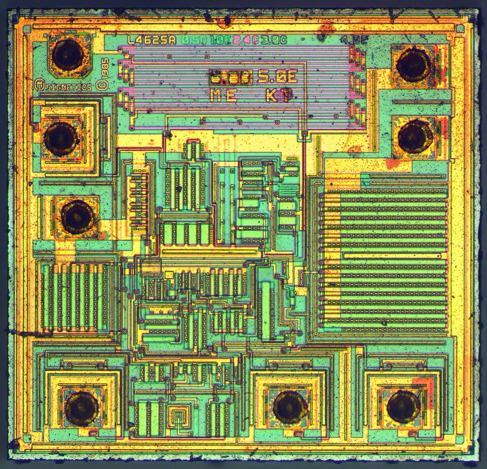
The silicon die of an NXP 7555, a CMOS descendant of the original bipolar 555. Credit: ZeptoBars, via Wikimedia Commons, CC BY 3.0.
CMOS means complementary metal-oxide-semiconductor, a process that can reduce power consumption and work across a wider supply range. Parts such as Texas Instruments' TLC555 and LMC555 preserve the familiar basic function and pin arrangement while changing important electrical limits. A circuit designer still has to read the datasheet because output current, supply current, input behavior, and maximum frequency vary among versions.
The dual 556 placed two timers in one package. A quad version, the NE558, put four timers in a 16-pin package, with fewer pins available to each timer, and many of those parts have since been discontinued. Other manufacturers produced their own bipolar and CMOS interpretations, and suffixes identified temperature ranges, packages, and electrical grades. That variety made the family more useful, but it also created a trap. Two parts with “555” in their names can fit the same socket while behaving differently at low voltage, high frequency, or heavy output current.
CMOS versions address one of the original bipolar design's biggest weaknesses: supply current. They are well suited to battery circuits that spend long periods waiting for an event. The old bipolar part can often source or sink more current directly, although using an external transistor is still the safer choice for substantial loads. Neither version is automatically better. The circuit decides which tradeoff matters.
The old bipolar NE555 has not vanished. Texas Instruments still listed it as an active product when this research was completed in October 2026. Modern distributor prices remain in the same broad spirit as Fury's original strategy: a useful timing function for pocket change, although historical and modern prices here are nominal and should not be compared as if inflation did not exist.
Signetics itself changed hands. Philips bought the company in 1975, and its semiconductor business later became part of NXP. Other 555 makers were absorbed too, among them National Semiconductor into Texas Instruments in 2011, which is one reason a current 555 may carry a different company's name than the one in an older datasheet.
Uses beyond timing
Camenzind designed the 555 as a general-purpose timer, and people found uses he had not planned. In an article on redesigning the old 555, published in IEEE Spectrum in 1997, he said that most of its applications were ones he had never contemplated. In the late 1980s, some designs used a 555 as a simple switching voltage regulator, before dedicated switch-mode regulator chips such as the LT1070 (1987) were widely available. Pulse-width modulation, tone generation, touch switches, and missing-pulse detectors all use the same eight pins connected in different ways.
A 2017 book claims that more than a billion 555 timers are made each year and calls it probably the most popular integrated circuit ever made. That figure is a claim from a book and not a published production count, but the 555's long list of manufacturers supports the general point. Camenzind died in 2012.
Why the 555 survived microcontrollers
A small microcontroller can reproduce many 555 applications in software. It can also add menus, communications, calibration, and complex timing patterns. That does not make a 555 pointless.
The 555 starts immediately, needs no firmware, and makes its timing visible through a few external parts. It is useful in simple products, repair work, quick prototypes, and teaching. On a breadboard, you can watch the timing capacitor charge with an oscilloscope and connect that analog movement directly to the digital-looking output pulse.
That visibility explains much of the chip's educational value. In astable mode, the capacitor rises toward the supply through resistance until it reaches the upper threshold. The discharge transistor then pulls it downward until it reaches the lower threshold. Changing the resistor or capacitor produces an immediate, understandable change in rate. A microcontroller timer can be more accurate and flexible, but its counting happens inside registers and software that a beginner cannot see with a meter.
The control-voltage pin exposes the upper threshold so another signal can move the timing level. This allows pulse-width modulation and simple frequency control. The reset pin can stop the cycle independently of the timing capacitor. These pins are why the device is more than a prepackaged blinking circuit. They let other parts of a system interrupt or reshape its behavior.
Real construction also teaches the limits of the ideal explanation. Long breadboard wires can pick up noise. A supply that jumps when the output changes can retrigger the circuit. A bypass capacitor near the power pins and a small capacitor on the control pin often prevent erratic behavior. Those details helped produce decades of application notes because the internal idea is simple while real power supplies and wiring are not.
Its limitations are equally educational. The bipolar version draws more current than many CMOS alternatives. Its thresholds and output are not perfect, and an astable oscillator built from ordinary resistors and capacitors is not a precision clock. Camenzind himself later criticized parts of the design. The part has lasted because its tradeoffs have stayed useful, and not because the design is flawless.
The 555 became a standard part because it compressed a broadly useful circuit into eight inexpensive pins. A recession pushed its designer out of a regular job, a marketing manager supported the project, and a redesign on a drive home removed one pin from the package. The resulting chip is easy to use because the timing circuit is built in, and the timing capacitor can be watched charging and discharging on an oscilloscope, which is why it remains a common first project for learning how timing circuits work.