
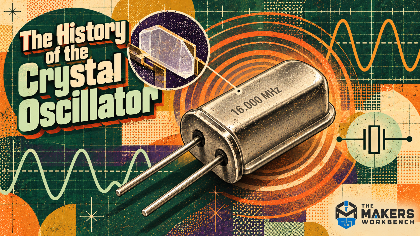
Open an old radio, a quartz watch, a computer motherboard, or a microcontroller board and you will probably find a small metal package whose job is to keep time. Inside many of those packages is a carefully cut piece of quartz driven into mechanical vibration by an electronic circuit.
A crystal oscillator works because quartz can trade electrical energy for mechanical motion and then turn that motion back into an electrical signal. The idea began with nineteenth-century physics, became tangled in an invention dispute after World War I, and matured through radio, wartime mass production, watches, and digital electronics.
This article traces the crystal oscillator from the discovery of piezoelectricity through the patent dispute, wartime production, quartz watches, and the timing parts used on boards today.
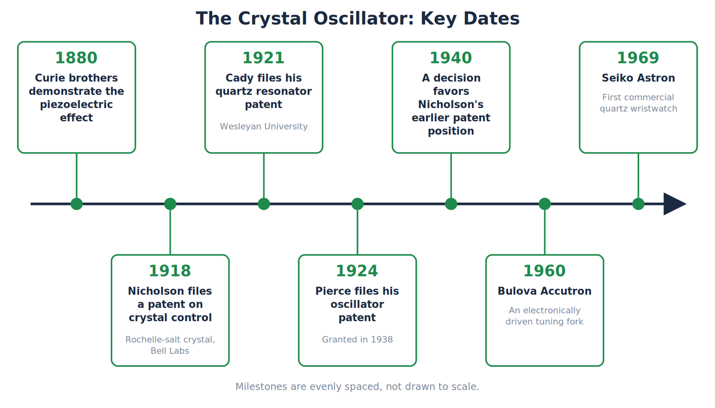
Key dates in the story of the crystal oscillator. Credit: The Makers Workbench.
A crystal that responds to electricity
In 1880, brothers Jacques and Pierre Curie demonstrated the piezoelectric effect in crystals. Piezoelectricity is the ability of certain materials to produce an electrical charge when mechanically stressed. Gabriel Lippmann predicted the reverse effect, in which an applied electric field causes the material to change shape, and the Curies confirmed it experimentally.
The movement is tiny, but a crystal can resonate. Resonance occurs when a system is driven near one of its natural frequencies and stores energy by moving back and forth. A playground swing is the familiar analogy. Small pushes timed to the swing's natural motion build into a larger response. The analogy stops at the scale and mechanism: a quartz plate flexes microscopically, and an electric field supplies the push.
During World War I, Paul Langevin investigated quartz resonators for use in sonar, which was another early demand for a stable, repeatable vibrating crystal.
Quartz did not win because it produced the strongest piezoelectric response. It offered an exceptionally stable resonance, could be cut in repeatable ways, and survived the electrical and mechanical demands of radio equipment.
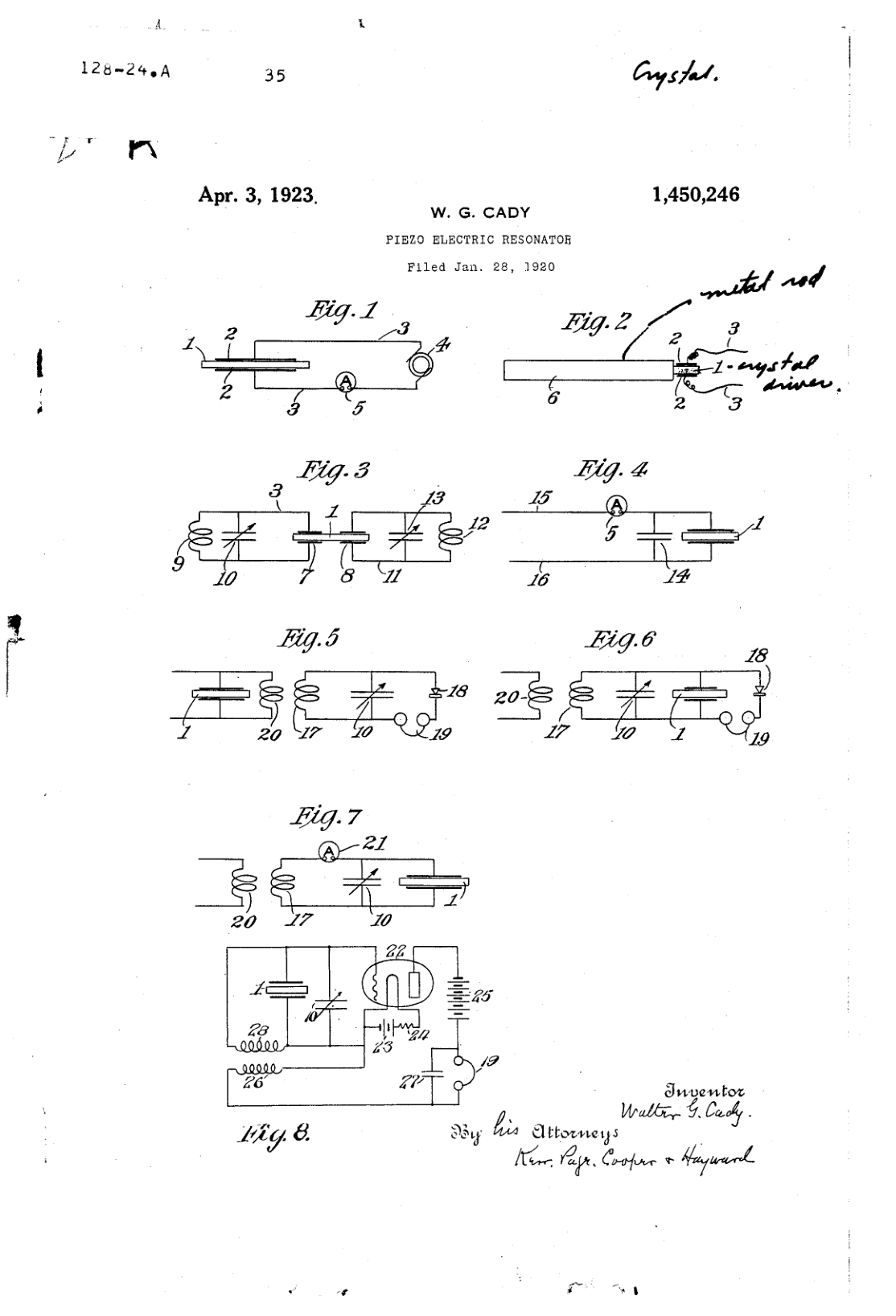
First sheet of Walter Cady's patent for a piezoelectric resonator. Credit: US Patent 1,450,246, Walter G. Cady, “Piezo Electric Resonator,” 3 April 1923. Public domain.
The first oscillator claims
World War I created demand for stable radio transmitters and receivers. Ordinary tuned circuits built from inductors and capacitors drifted as parts warmed, aged, or moved. A vibrating crystal offered a much sharper frequency reference.
Before quartz control, an oscillator's frequency depended directly on the electrical values of its inductor and capacitor. Temperature changed wire resistance, coil dimensions, and capacitance. Mechanical vibration moved parts. Even a hand near an exposed circuit could add enough capacitance to shift a high-frequency oscillator. Radio operators could retune the set, but a communication network needed stations to return to known channels reliably.
Alexander M. Nicolson of Western Electric's engineering department, the group that became Bell Telephone Laboratories, built a crystal-controlled oscillator using Rochelle salt in 1917 and filed a patent on it in 1918. Walter Guyton Cady of Wesleyan University experimented with quartz resonators and filed his important patent in 1921. Cady's work showed how a quartz bar could stabilize the frequency of a vacuum-tube oscillator.
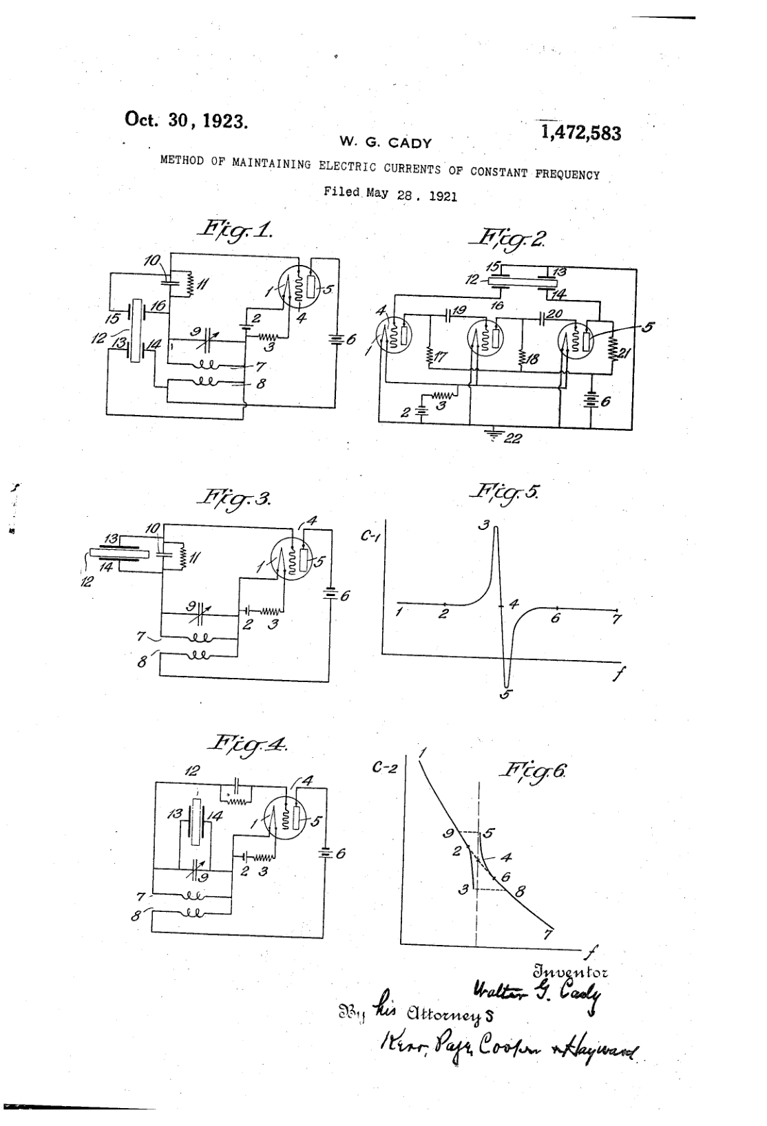
Cady's 1923 patent for keeping an electric current at a constant frequency with a crystal. Credit: US Patent 1,472,583, Walter G. Cady, 30 October 1923. Public domain.
The distinction matters. Nicolson had the earlier legal claim that later survived a long dispute, while Cady established the quartz engineering path that became historically influential. Saying either man simply “invented the crystal oscillator” erases what the other actually contributed.
George Washington Pierce at Harvard simplified the practical circuit further. His arrangement used the crystal with one pair of electrodes and a vacuum-tube amplifier in a topology that resembles later oscillator practice more closely than the earliest laboratory systems.
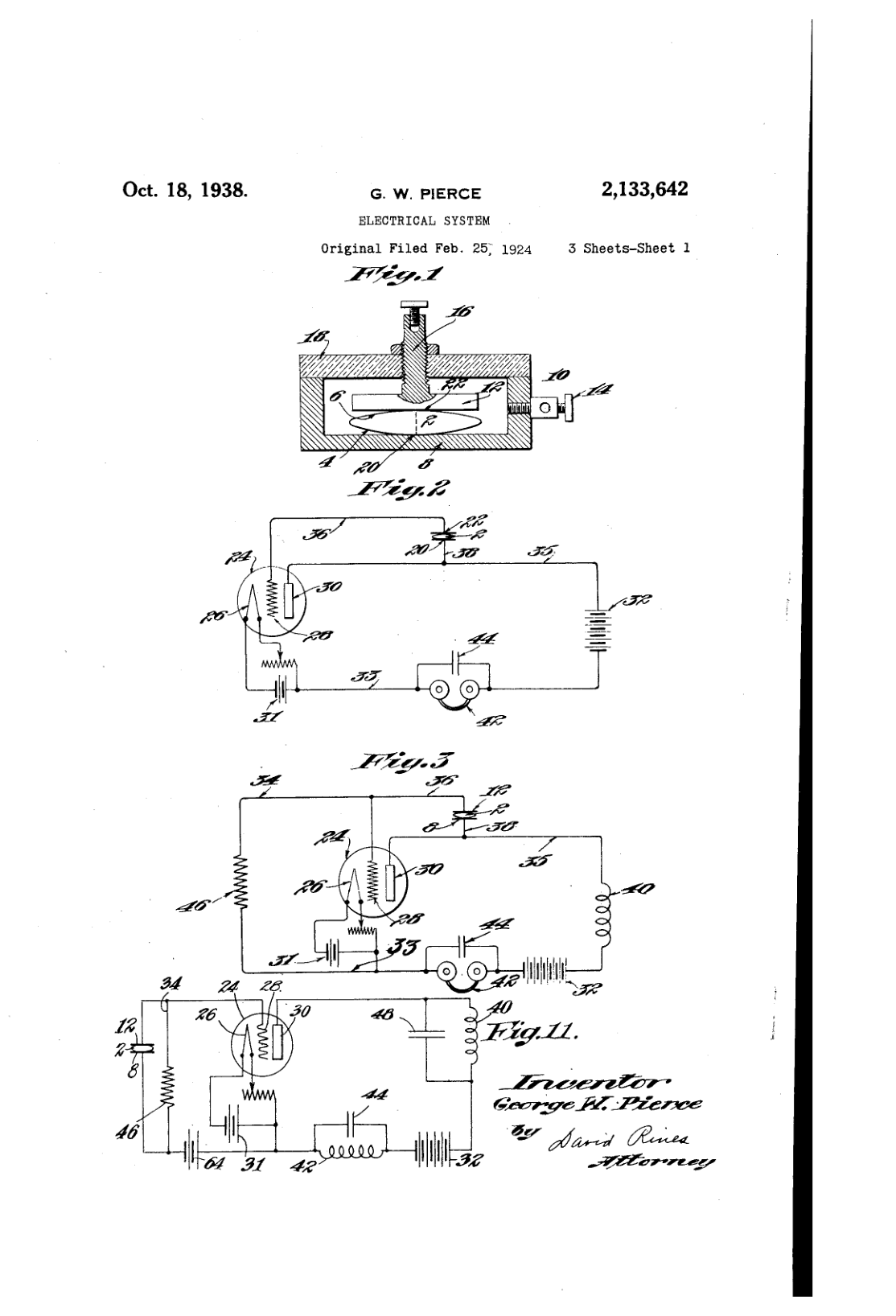
Sheet 1 of George Pierce's patent, filed in 1924 and granted in 1938. Credit: US Patent 2,133,642, George W. Pierce, “Electrical System,” 18 October 1938. Public domain.
The legal dispute outlasted the early experiments. A 1940 decision favored Nicolson's earlier patent position, but that did not erase Cady's quartz work or Pierce's practical circuit. Patent priority, first quartz demonstration, and the circuit ancestry visible in modern designs are three different historical questions. A useful account has to keep them separate.
Broadcasters adopted quartz quickly. Westinghouse installed a crystal oscillator in its flagship station, KDKA, in 1925, and by 1926 quartz crystals controlled many broadcast stations and were popular with amateur radio operators. Some amateurs ground crystals by hand with abrasive slurry to raise their frequency slightly.
How a crystal controls frequency
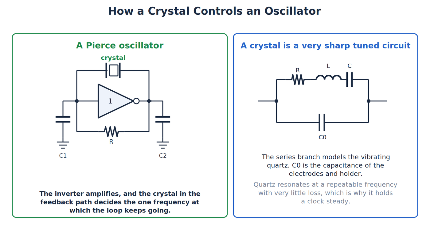
A Pierce oscillator and the electrical model of a crystal. Credit: The Makers Workbench.
A quartz resonator can be represented electrically by a small series resistance, inductance, and capacitance, together with a parallel capacitance created by the electrodes and package. These are equivalent circuit elements rather than separate tiny parts hidden inside the can.
Near resonance, the crystal's impedance changes rapidly with frequency. Impedance is the opposition a circuit presents to alternating current, including both resistance and frequency-dependent effects. The oscillator amplifier feeds a portion of its output back through the crystal. At the frequency where the loop has the right gain and phase, noise grows into a steady waveform. At nearby frequencies, the crystal does not support the loop as strongly.
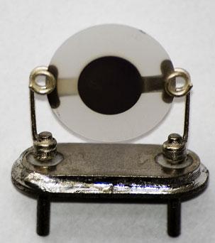
A resonator with the case removed: a round quartz plate held by two clips. Credit: Jakub Šerých, public domain. Crop on Wikimedia Commons, 2017.
This is why a crystal is a frequency-selective component, not a complete oscillator by itself. A bare crystal needs an amplifier and supporting components. A crystal oscillator module, often labeled XO, contains the resonator and active circuit in one package and produces a ready-to-use clock signal.
The crystal's marked frequency is also a contract with its circuit. A parallel-resonant crystal is specified for a particular load capacitance. The two capacitors commonly placed around a microcontroller crystal, together with pin and board capacitance, create that load. Choose the wrong values and the circuit may still run, but the frequency can be pulled away from the specification.
Series resonance and parallel resonance describe two nearby operating points in the equivalent circuit. Near series resonance, the motional inductance and capacitance cancel and the crystal's impedance becomes low. Slightly above that point, the crystal can behave inductively until it reaches parallel resonance with the package capacitance. Oscillator circuits are designed around one of these conditions, which is why ordering the correct frequency alone is not enough.
Startup adds another practical constraint. The amplifier must provide enough loop gain to overcome the resonator's losses, but too much drive can heat or damage a small crystal. Datasheets specify an equivalent series resistance and a maximum drive level for this reason. A circuit that works with one package or frequency may fail to start with another even when both cans carry similar labels.
The cut becomes part of the design
Quartz is anisotropic, which means its properties depend on direction through the crystal. A resonator's behavior changes according to the angle at which the blank is cut from the parent crystal.
Early X-cut and Y-cut resonators made radio frequency control practical, but they could drift substantially with temperature. Engineers developed rotated cuts with better temperature behavior. Issac Koga of the Tokyo Institute of Technology reported a temperature-insensitive orientation, the R1-cut, in 1933, work later recognized as an IEEE Milestone in 2017, and the AT-cut followed in 1934. The AT-cut became the general-purpose workhorse for radio and electronic timing. The SC-cut, developed in 1974, offered advantages in oven-controlled oscillators that demand very high stability.
An oven-controlled crystal oscillator, or OCXO, keeps the resonator at a carefully regulated temperature. A temperature-compensated crystal oscillator, or TCXO, instead measures or predicts temperature effects and adjusts the circuit electronically. Both approaches improve stability, but they cost more and consume more power than a basic crystal.
The cutting angle, blank shape, electrode pattern, mounting, enclosure, and aging characteristics all affect performance. A frequency printed on a can looks simple because the difficult mechanical details were settled at the factory.
Temperature curves also explain why a specification is usually stated in parts per million, abbreviated ppm. One part per million is one unit of error in one million units. A 10MHz crystal with a 20 ppm tolerance could begin as much as roughly 200Hz away from its nominal frequency before temperature and aging are considered. That may be excellent for a microcontroller clock and unacceptable for a precision frequency standard.
Aging is the slow frequency change that continues after manufacturing. Stress relaxes, surfaces change, and tiny amounts of contamination or material movement affect the resonator. Good packaging reduces these effects but cannot make them zero. Precision systems specify initial tolerance, temperature stability, and aging separately because they describe different sources of error.
War makes crystals a mass product
Radio made crystals valuable. World War II made them an industrial priority.
Military communications equipment needed many channels that would stay on frequency in vehicles, aircraft, ships, and field radios. The United States produced tens of millions of quartz plates during the war. Some radios carried sets of individual crystals so an operator could select a channel by switching resonators.
Mass production required more than cutting natural quartz. Manufacturers had to orient the crystal, grind and lap the blank, apply electrodes, test frequency and activity, and package it without allowing dirt or mechanical stress to spoil its behavior. The war accelerated the measurement and production techniques that later supported commercial electronics.
The physical challenge was visible inside the equipment. A multichannel field radio could carry a bank of crystals, one for each assigned frequency. Changing channels meant switching a different mechanical resonator into the oscillator. The arrangement used space and inventory, but it gave operators repeatable channels without asking them to tune a continuously adjustable circuit by ear.
Wartime crystals were cut from natural quartz, nearly all of it imported from Brazil, and shortages of good quartz led to research on growing it. Bell Labs developed a hydrothermal process for growing synthetic quartz at commercial scale in 1950, and by the 1970s virtually all quartz used in electronics was synthetic, which improved both supply and consistency. Companies built a broad ecosystem around resonators, filters, frequency-control modules, and the equipment needed to make and test them.
Quartz moves onto the wrist
Quartz kept time well before it reached the wrist. In 1927, J. W. Horton and Warren Marrison at Bell Labs built a clock around a 50kHz quartz oscillator, and Marrison developed the first quartz-crystal clock in 1928. Quartz clocks then became the most accurate timekeepers, replacing pendulum clocks, until atomic clocks overtook them in the 1950s.
Electronic timekeeping is often compressed into one misleading sentence. Bulova's Accutron, introduced in 1960, used an electronically driven metal tuning fork. It was not a quartz watch. Seiko's Astron, released in 1969, was the first commercial quartz wristwatch.
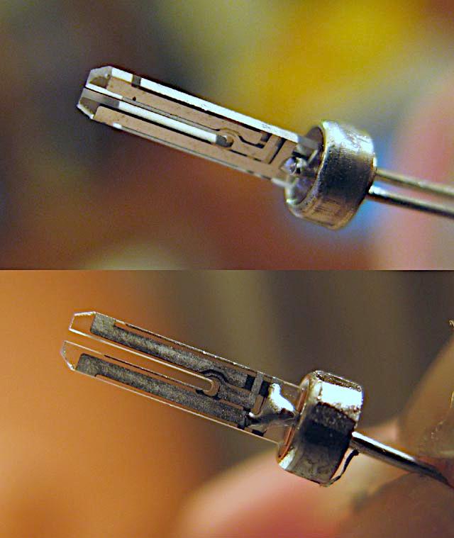
An opened watch crystal. The tiny tuning-fork blank is the part that vibrates. Credit: Chribbe76, 2007, released to the public domain. Colour correction on the Commons file by Rsuessrb, 2022. https://commons.wikimedia.org/wiki/File:Inside_QuartzCrystal-Tuningfork….

Early quartz watches used relatively low crystal frequencies such as 8,192 hertz. Later designs standardized around 32.768 kilohertz, or 32,768 cycles per second. That number is a power of two, so a chain of binary divider stages can repeatedly halve it until one pulse per second remains.
The crystal does not directly move the hands. It supplies a stable rhythm. Divider electronics count the cycles, and a motor or display system turns that count into visible time. Improvements in low-power complementary metal-oxide-semiconductor electronics, usually shortened to CMOS, helped make the system small and efficient enough for a wristwatch. A photolithographic process invented by Juergen Staudte at North American Aviation in 1968 made crystals small enough for use in watches.
The timing part on a modern bench
The large through-hole HC-49 package remains familiar to makers, especially around older microcontrollers and radio circuits. Smaller surface-mount crystals now dominate compact products. Integrated oscillator modules add the amplifier, while voltage-controlled, temperature-compensated, and oven-controlled versions serve systems that need progressively tighter frequency control.
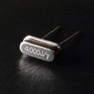
The metal can most makers recognize, stamped as a 4MHz crystal. Credit: Natrij, 2005. Via Wikimedia Commons, uploaded by Omegatron. CC BY-SA 3.0. https://commons.wikimedia.org/wiki/File:Crystal_oscillator_4MHz.jpg.

Microelectromechanical-system oscillators, called MEMS oscillators, provide a modern alternative using microscopic silicon structures and supporting electronics. They can offer ruggedness, small size, and programmable output options. They have not made quartz disappear. Designers choose between technologies based on stability, phase noise, power, startup, environmental requirements, availability, and price.
Phase noise describes the small, rapid departures from a perfectly periodic signal when viewed around its nominal frequency. Jitter describes timing variation from one edge or cycle to another. These are related ways of describing clock purity. A simple microcontroller may tolerate far more of either than a radio receiver, high-speed data link, or precision converter.
Package labels can hide several levels of integration. A bare crystal is a passive resonator. An XO combines the resonator with an oscillator circuit. A voltage-controlled crystal oscillator, or VCXO, permits a small electronic frequency adjustment. A TCXO compensates temperature, and an OCXO controls temperature directly. The extra letters represent real circuitry, calibration, power, warm-up time, and cost.
That hierarchy helps explain why a commodity crystal and a laboratory frequency standard can both depend on quartz while belonging to very different price classes. One keeps a microcontroller close enough to its expected clock. The other may serve as the reference against which other clocks are measured.
The 2026 research for this article found basic crystal and oscillator parts ranging from inexpensive commodity devices to costly precision modules. One HC-49 price was only a reference price on an out-of-stock page, so it should not be treated as a live market quote. The metal package alone does not give the tolerance, stability, or load capacitance, and a listing does not show whether the part can actually ship.
The crystal oscillator endured because it connects two dependable worlds. Quartz provides a repeatable mechanical resonance. Electronics sustains and counts it. From vacuum-tube transmitters to wristwatches and microcontrollers, the packages changed dramatically while the core relationship stayed recognizable.
A silver can stamped with a frequency therefore holds a sliver of quartz vibrating steadily, and the circuit around it counts those vibrations to keep time.