
The operational amplifier, usually shortened to op-amp, is one of the most reusable building blocks in electronics. Give it the right feedback network and the same basic device can amplify a sensor, filter noise, compare levels, generate a waveform, or perform arithmetic. The familiar eight-pin chip grew from a much older chain of telephone engineering, vacuum-tube computers, and difficult early integrated circuits.
The popular 741 did not invent the idea. Its achievement was making a 1940s computing technique far easier to buy and use.
The history also explains why an op-amp circuit needs feedback to behave predictably, which a datasheet usually does not. This article keeps the math light and follows the sequence of developments.
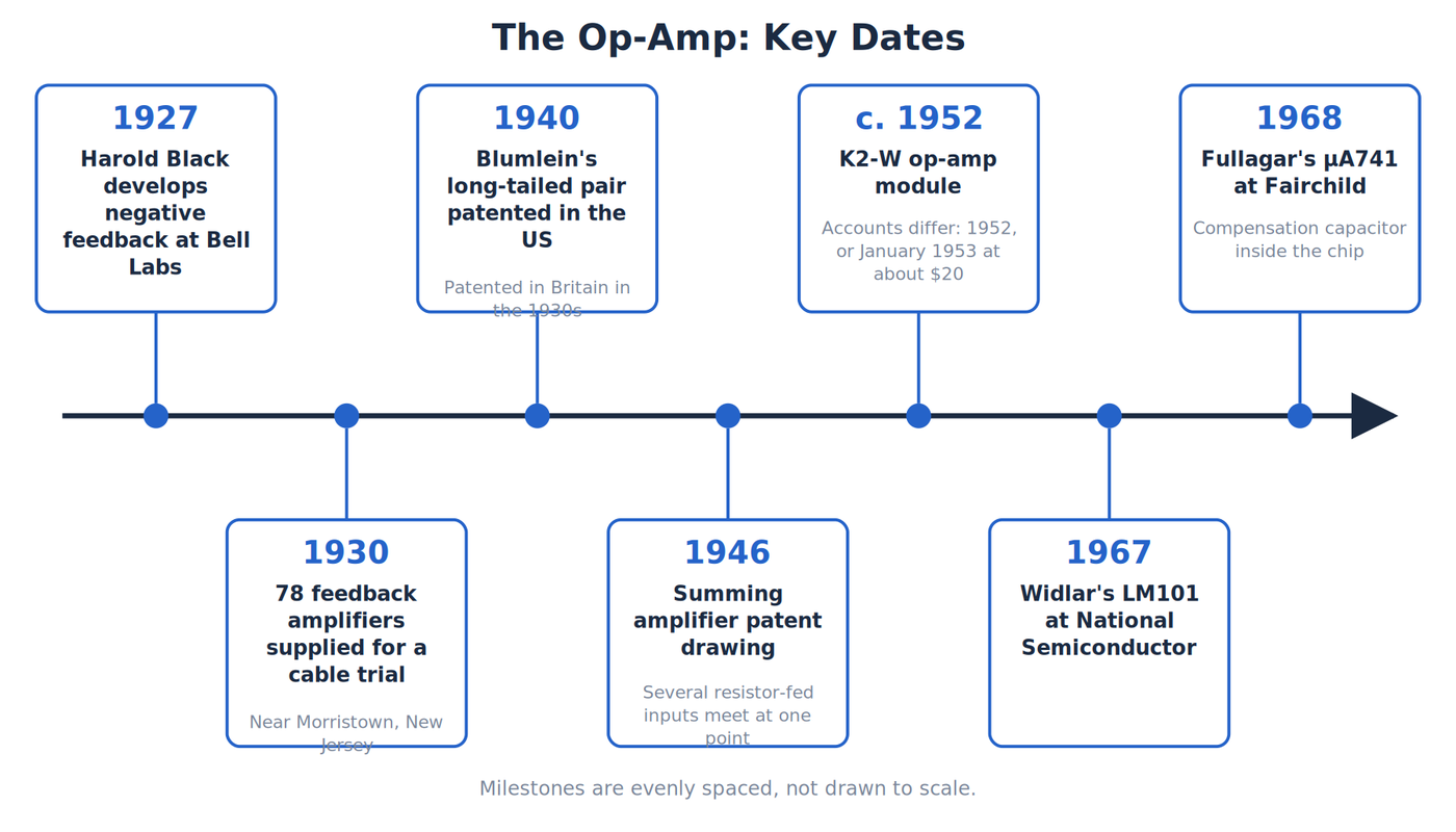
Key dates in the story of the operational amplifier. Credit: The Makers Workbench.
Feedback before the op-amp
The story begins with telephone amplifiers. Long-distance telephone lines needed gain, which means an increase in signal amplitude, but more gain also made an amplifier's distortion and instability harder to control.
In 1927, Bell Labs engineer Harold S. Black developed negative feedback while traveling to work. In a negative-feedback amplifier, part of the output is inverted and returned to the input. The amplifier uses some of its enormous raw gain to correct its own errors. The final gain becomes lower, but it is much more predictable, linear, and stable.
Black sketched the idea on a newspaper. The United States Patent Office treated the application with skepticism, and the patent process lasted about nine years. The delay makes sense when you remember how strange the proposal sounded: deliberately feed an amplifier's output back into its input, sacrifice gain, and receive a better amplifier in return.
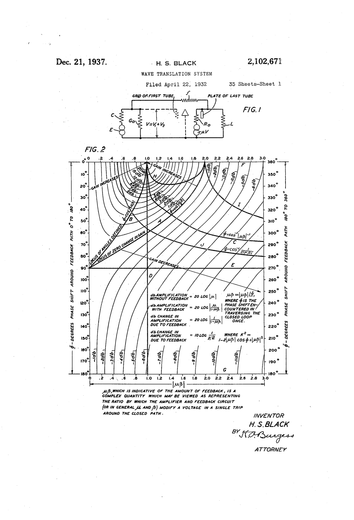
Sheet 1 of Harold Black's patent: the feedback loop and its closed-loop chart. Credit: H. S. Black, US patent 2,102,671, “Wave Translation System,” sheet 1 (1937).
The laboratory results made the strange proposal difficult to dismiss. Late in 1927, a three-stage experimental repeater reduced distortion by roughly 100,000 to one across a band from 4 to 45 kilohertz. In 1930, Western Electric supplied 78 feedback amplifiers for a cable trial near Morristown, New Jersey. The test chained repeaters to simulate thousands of miles of telephone line while keeping speech intelligible.
Feedback still carried a danger. If signals around the loop return with the wrong phase, the correction reinforces the error and the amplifier oscillates. Harry Nyquist's stability criterion and later design methods associated with Hendrik Bode gave engineers systematic ways to predict that behavior. Black supplied the powerful idea, while stability theory made it safe to apply broadly.
That feedback principle became the foundation beneath the later op-amp. It also explains a central fact about using one. An op-amp's open-loop gain, the gain with no feedback path, is extremely large and poorly suited to precise work by itself. External feedback components turn that excess gain into a useful, controlled circuit.
Two inputs and one important difference
An op-amp responds to the difference between two input voltages. One input is non-inverting, which means a positive change tends to push the output positive. The other is inverting, which means a positive change tends to push the output negative.
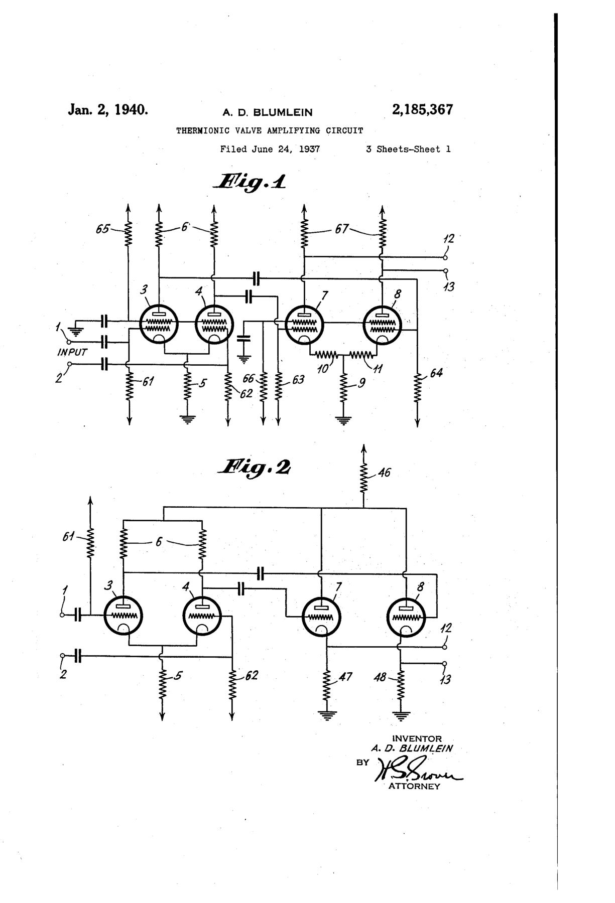
Alan Blumlein's 1940 patent drawings of thermionic differential and push-pull amplifier circuits. Credit: A. D. Blumlein, US patent 2,185,367, sheet 1 (1940).
This differential input has its own ancestry. Alan Blumlein's long-tailed-pair circuit, patented in Britain in the 1930s and in the United States in 1940, used two active devices sharing a common current path. The arrangement could amplify the difference between two signals while rejecting what they had in common.
Common-mode rejection is still a key op-amp specification. If both inputs pick up the same noise, a good differential amplifier largely ignores it and responds to the small difference the circuit actually cares about.
The description “responds to the difference” has limits. An op-amp does not simply subtract two voltages under every condition. Its inputs and output must stay within their allowed voltage ranges, and the output can supply only limited current. Feedback makes the circuit behave predictably only while the amplifier itself remains inside those limits.
The wartime mathematical amplifier
During World War II, electronic analog computers used voltages to represent mathematical quantities. Engineers needed circuits that could add several voltages, change their signs, integrate them over time, and solve differential equations used in ballistics and control problems.
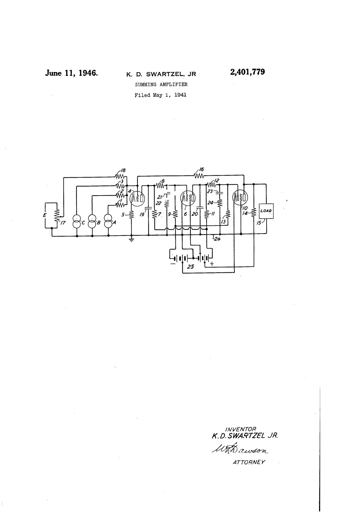
The single drawing sheet of the 1946 summing-amplifier patent: three tubes, one feedback resistor and several inputs. Credit: K. D. Swartzel, Jr., US patent 2,401,779, “Summing Amplifier” (1946).
Karl D. Swartzel Jr. developed an amplifier for Bell Labs' M-9 gun director that used three vacuum tubes. The patent application was filed in 1941. A 1946 patent drawing shows a summing arrangement in which several resistor-fed inputs meet at one point. With high gain and negative feedback, that point stays near a stable reference voltage. The currents through the input resistors add, and the output moves enough to balance them through the feedback path.
That behavior gave the device its name. It was an amplifier used to perform operations. Early literature used forms such as “operational amplifier” for these computing modules before the phrase became attached to a standard integrated circuit.
The name was formalized in 1947, when John R. Ragazzini of Columbia University formally defined and named the operational amplifier. His paper cited a design by his student Loebe Julie that introduced the first op-amp with two inputs, a differential input, which is the arrangement every later op-amp uses.
The operations went beyond addition. Put a capacitor in the feedback path and the circuit can integrate a changing voltage over time. Put a capacitor at the input and a resistor in feedback and it can approximate differentiation, responding to how quickly the input changes. Networks of these amplifiers could model motion, feedback systems, and other equations without executing digital instructions.
An analog computer represented variables as continuous voltages and let several circuit blocks operate at the same time. That made it fast for a particular model, but the result depended on component accuracy, noise, drift, and careful setup. The op-amp's job was to make each mathematical block predictable enough for the larger machine to work.
The early tube amplifiers drifted, which means their output slowly wandered even with a fixed input. In 1949, Edwin A. Goldberg designed a chopper-stabilized amplifier that reduced drift and offset. Chopper stabilization is still used in modern precision op-amps.
A simple inverting amplifier still uses the same logic. If the input resistor is 10 kilohms and the feedback resistor is 100 kilohms, the closed-loop voltage gain is approximately negative ten. A 0.1-volt positive input asks for about a 1-volt negative output, provided the power supplies and device limits allow it.
From racks to catalog modules
Early operational amplifiers were not tiny or convenient. They used vacuum tubes, generated heat, and often required high positive and negative power supplies. Philbrick's K2-W, introduced commercially in the early 1950s, made the concept available as a module a designer could order rather than build from scratch. It still required supplies around plus and minus 300 volts.
Sources disagree slightly on the commercial dates and price. One account says the K2-W was developed in 1952 and appeared in January 1953 for $20. Engineer Bob Pease remembered it selling from 1951 through 1971 for $22. The safe conclusion is that it became an orderable product in the early 1950s and remained available for roughly two decades.
The specifications sound extraordinary beside a modern chip. The module used two 12AX7 dual triodes, plugged into an octal socket, and could swing roughly plus or minus 50 volts. Open-loop gain was in the range of 10,000 to 20,000. Its compact applications manual mattered almost as much as the hardware because it taught engineers how to build closed-loop summers, integrators, and other standard configurations.
Solid-state discrete op-amps followed. Around 1961, units such as Philbrick's P45 reached about 94 dB of gain on supplies of plus and minus 15V, a far lower and safer voltage than the tube modules needed. By 1962, potted modules that plugged into circuit boards made the op-amp a single black-box part.
That module marks an important change. The op-amp had moved from a specialized wartime computer circuit toward a general engineering component. Designers used commercial modules in industrial control, instrumentation, and research systems.
Transistors then reduced size and power, but turning a high-performance op-amp into one monolithic integrated circuit created new problems. Monolithic means the active devices and many supporting components are formed together on one semiconductor die. Capacitors and accurate large-value resistors consume precious chip area, while transistor characteristics vary with temperature and manufacturing.
Solid-state modules bridged the gap between vacuum-tube assemblies and monolithic chips. They reduced the high supply voltages and the physical size, but they were still assembled from multiple discrete parts. A module remained expensive compared with the integrated circuits that would follow. The useful abstraction was already established, and manufacturing had to catch up.
The monolithic breakthrough
Fairchild Semiconductor's Bob Widlar became a central figure in the transition. The µA702 (1963) was the first monolithic integrated-circuit op-amp, though it had limited success, and the µA709 (1965) made monolithic op-amps the dominant kind. Together they demonstrated that a useful op-amp could be built on a single chip. Widlar developed circuit techniques that produced small internal currents without requiring impractically large resistors. Those current-source and biasing ideas became part of the language of analog integrated-circuit design.
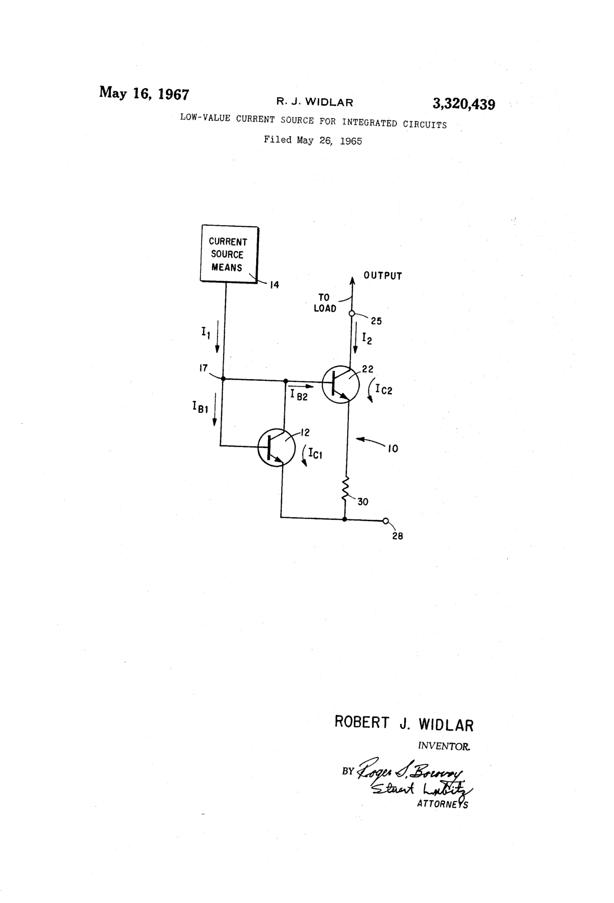
Bob Widlar's current-source drawing, a building block of monolithic amplifiers. It is not a 741 schematic. Credit: R. J. Widlar, US patent 3,320,439 (1967).
The early monolithic parts still demanded care. In particular, a designer often had to add external frequency-compensation components. Compensation deliberately shapes an amplifier's high-frequency response so that negative feedback remains stable instead of turning into unwanted oscillation.
Fairchild's µA709 became a widely used early monolithic op-amp, but its external compensation requirements gave the designer enough freedom to make a circuit fast, slow, stable, or accidentally unstable. The part was important precisely because it exposed the remaining difficulty. Putting an amplifier on one die did not automatically make feedback easy to use.
The 709 also carried harsher failure modes than a beginner might expect. A sustained short circuit could damage its class-B output stage unless the user added protection. Exceeding the allowed common-mode input range could make it latch, and too much differential voltage could damage its input transistors. An op-amp could now fit in a small package, but the circuit around it still had to protect and stabilize it.
After leaving Fairchild for National Semiconductor, Widlar answered with the LM101 in 1967. It needed only one external compensation capacitor, included short-circuit protection, and tolerated a much larger differential input. National later put the capacitor beside the die in a hybrid product and then on the chip in the LM107. That competition created the immediate context for Fullagar's 741.
David Fullagar's µA741, introduced by Fairchild in 1968, placed a compensation capacitor inside the chip. That choice gave up some flexibility and speed, but it made the device much harder to misuse in ordinary feedback circuits. The 741 became a teaching standard and an industry reference point because it was approachable, widely copied, and available from multiple manufacturers.
Internal compensation was a product decision as much as a circuit decision. Many customers preferred a slightly slower amplifier that behaved predictably in ordinary closed-loop circuits. That tradeoff helped move the op-amp from specialist analog design into routine laboratory, industrial, and educational work.
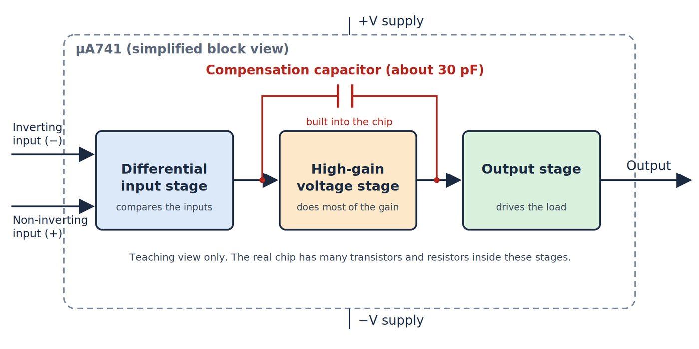
A simplified block view of the µA741: a differential input stage, a high-gain voltage stage with the roughly 30pF compensation capacitor built in, and an output stage. It is a teaching diagram, not the full schematic. Credit: The Makers Workbench.
What an op-amp really promises
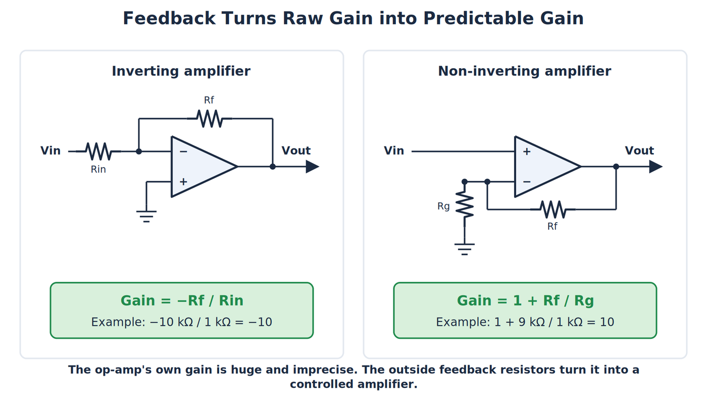
Two classic feedback circuits show how outside resistors set the gain. Credit: The Makers Workbench.
The ideal op-amp model is intentionally simple. It has infinite open-loop gain, draws no current at either input, produces zero output resistance, and responds instantly at every frequency. No real device does those things. The model is useful because feedback can make a real amplifier behave close to it over a limited range.
That range matters. The classic 741 is slow by modern standards. It has noticeable input offset voltage, its inputs cannot operate close to both supply rails, and its output is not rail-to-rail. Rail-to-rail describes a device designed to accept inputs, produce outputs, or both over most of the voltage range between its power-supply rails.
A comparator is a close relative, but it is not simply another name for an op-amp. A comparator is designed to switch states quickly when one input crosses the other. An op-amp is normally designed for stable linear operation with feedback. Substituting one for the other can produce slow transitions, recovery problems, or oscillation.
Slew rate supplies another practical limit. It describes how quickly the output voltage can change, usually in volts per microsecond. If a signal asks the output to move faster than the amplifier allows, a sine wave can turn into a ramp-like shape. Gain-bandwidth product describes a different limit: as closed-loop gain rises, the usable frequency range generally falls. Those two specifications help explain why one op-amp cannot be ideal for precision direct-current measurements, audio, and very fast video at the same time.
Input offset voltage is the small unwanted difference the amplifier behaves as though it sees even when the real inputs are equal. Bias currents are the small currents that flow into or out of the input pins. Modern precision devices can make both extremely small, but neither disappears from real hardware. The ideal model remains a starting point, followed by the datasheet.
The same idea in a much larger family
Modern op-amps cover needs the 741 could not address well. Precision devices minimize offset and drift. CMOS op-amps draw very little input current and can run from low supply voltages. Instrumentation amplifiers accurately recover small differential signals in the presence of larger common-mode voltages. High-speed amplifiers handle video and communications. Audio parts prioritize noise and distortion.
The 741 did not end the story. In the 1970s, designs with JFET inputs combined higher speed with very low input current. In 1972, single-supply op-amps appeared, and the quad LM324 became an industry standard because it works from one positive supply, such as 5V, without needing a negative rail. In the decades since, supply voltages have fallen to 5V, 3.3V, and even 1.8V, and rail-to-rail outputs have become common.
This family is embedded in everyday systems even when the package is invisible. Op-amps condition temperature, pressure, light, and strain sensors before an analog-to-digital converter reads them. They filter audio, regulate power supplies, drive analog control loops, and create reference voltages. Many microcontrollers include op-amp-like analog blocks on the same die, continuing the same trend from rack to module to chip to subsystem.
The applications also explain why the 741 is best treated as a historical and teaching reference rather than a universal recommendation. A battery-powered sensor may need a low-voltage, rail-to-rail CMOS part. A thermocouple amplifier may need very low offset and drift. A photodiode may need low input current and noise. The circuit's signal and power conditions choose the op-amp, not familiarity with one famous part number.
The prices show how mature the technology has become. In October 2026, the research for this article found a DIP 741-type part listed for $1.32, while a small CMOS rail-to-rail device sold in quantities of five for roughly 14 cents each. Those are current snapshots rather than inflation-adjusted comparisons, but they illustrate the scale of modern manufacturing.
The long story is more useful than a single inventor label. Black supplied the feedback principle. Differential circuits provided the two-input front end. Wartime engineers used high-gain feedback amplifiers to perform mathematics. Commercial modules made them orderable. Widlar and other integrated-circuit designers made them monolithic. Fullagar's internal compensation made one version easy enough to become nearly universal.
An op-amp on a breadboard today uses all of those ideas at once: feedback, a differential input, high gain, and on-chip compensation. The package is inexpensive, and its design reflects almost a century of engineering decisions, from telephone repeaters to analog computers to integrated circuits.