
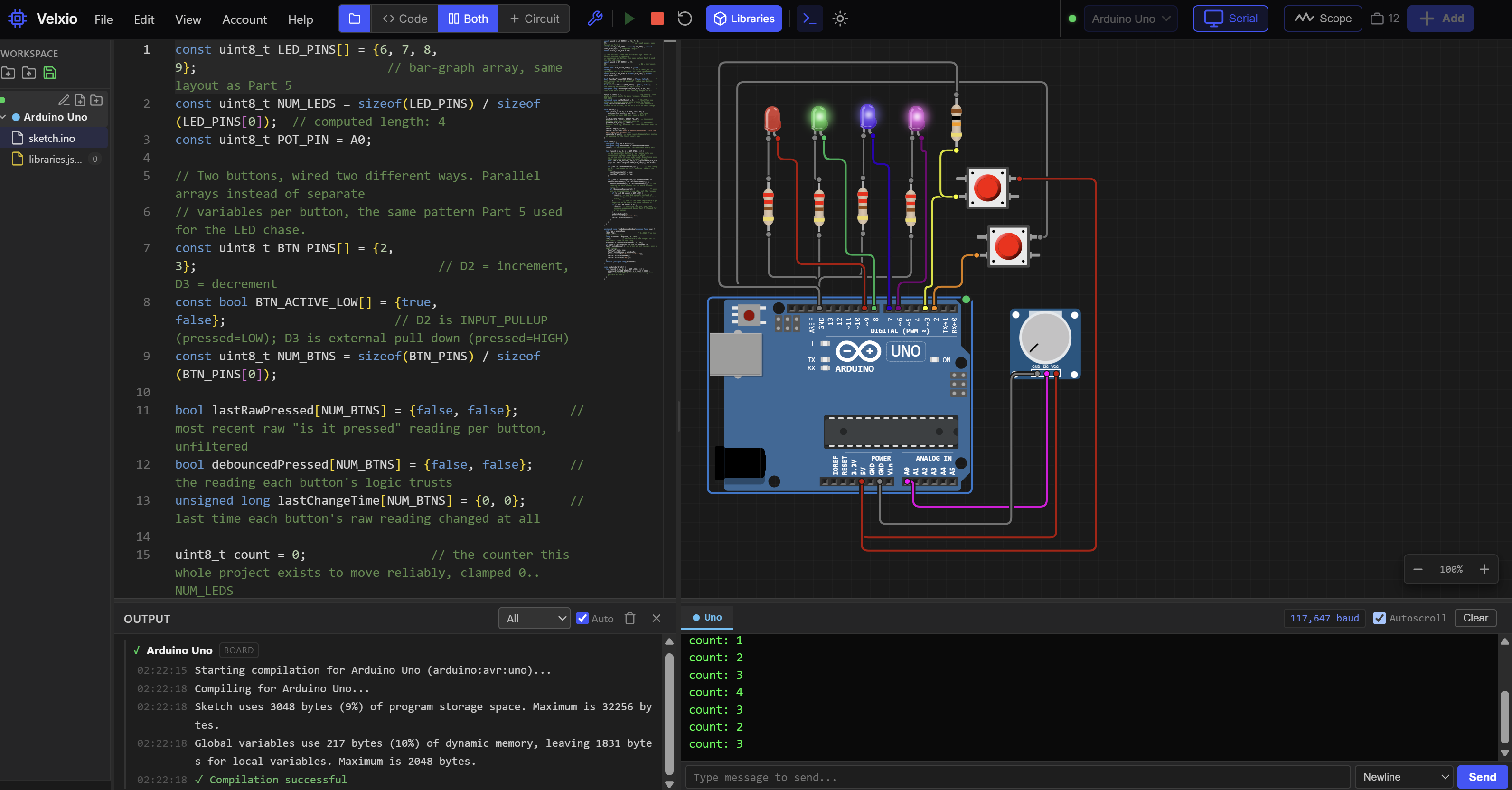

Part 6 left you with a counter that never misses a press and never double-counts one, because you finally understood why a mechanical button lies to you for a few milliseconds every time it's touched, and you built real millis()-based debounce logic to filter that lie out. That's a real skill. But notice what you did to get there: you watched the bar graph misbehave, turned a knob, watched it get better, and stopped when it looked right. That works when the bug is visible, repeatable, and only has one cause. Most bugs aren't that polite.
Here's a bug that isn't polite: your sketch works perfectly with the Serial Monitor open, and falls apart the instant you close it and run on battery power alone. Or you "fix" a problem by changing three things at once, it starts working, and you have no idea which of the three mattered, so the next bug in the same family costs you just as much time. Or the compiler spits out forty lines of red text for a one-character typo, and you stare at it feeling like the error message and your real mistake live in two different universes. Part 3 gave you a fast five-step checklist for exactly the kind of bug that checklist can catch: wrong board selected, a hidden delay(), a part that isn't plugged in at all. Keep using that checklist. It's still the fastest first move, always run it first. This article exists for what's left over once that checklist comes back clean and the bug is still there staring at you.
What you'll walk away with is a real method, five deliberate steps you can run in order on any bug, hardware or software, in this series or completely outside it. Pin numbers below are Uno/Nano defaults, same as the rest of this series, and the method itself doesn't care what board you're on at all. By the end, you'll use that method to hunt down three bugs I've planted on purpose in a modified copy of Part 6's own counter sketch, one that looks almost identical to the working version but isn't, and you'll fix all three using nothing but the method, not luck.
The Debugging Method, Step by Step
Real debugging isn't intuition and it isn't luck either, even though it can feel like both when you watch someone experienced do it. It's closer to what a doctor does with a patient's symptoms, or what a detective does with a crime scene: a small number of disciplined steps, run in order, that turn "something is wrong" into "I know exactly why, and I know exactly what I changed to fix it." Here are the five steps, and we'll use each one for real before this article ends.
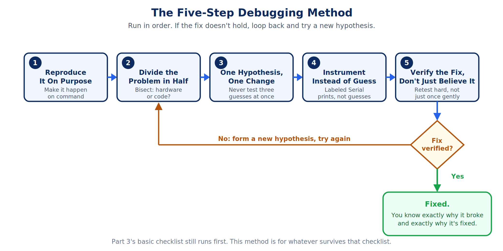
Step 1: Reproduce It On Purpose
Before you change a single line of code, you need to be able to make the bug happen on command, not just remember that it happened once yesterday. An intermittent bug you can't reliably trigger is nearly impossible to fix, because you can't tell the difference between "I fixed it" and "it happened not to occur this time." Ask yourself: does it happen every time you press the button fast? Only after the board's been running for ten minutes? Only with the Serial Monitor open? The answer to that question is often most of the clue.
This matters more than it sounds like it should. Say a counter occasionally skips a number. If you can't yet say "it skips every time I press faster than about three times a second," you don't have a bug report, you have a feeling. Spend five real minutes here before touching any code. A repeatable trigger turns an invisible problem into a visible, testable one, and every step after this one depends on being able to make the bug happen again whenever you need to check your fix.
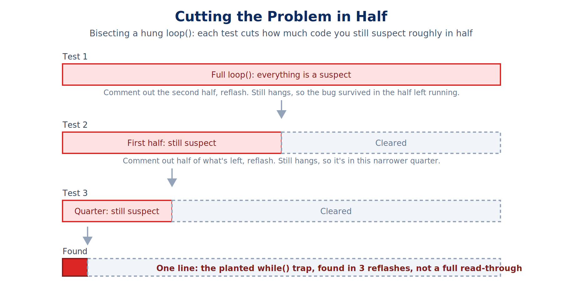
Step 2: Divide the Problem in Half
Once you can reproduce it, the fastest way to find where it lives is to cut the possibilities in half, over and over, the same way you'd find a word in a paper dictionary by opening to the middle instead of reading from page one. Is the bug in the hardware or in the code? Comment out (or physically disconnect) half of what's involved and see if the bug survives. If it does, the surviving half contains it. If it doesn't, the half you removed contained it. Repeat on whichever half is left.
A concrete example: your sketch hangs sometime after ten seconds of running. Instead of reading every line hoping to spot the problem, comment out the second half of loop() and reflash. Still hangs? The bug is in the first half. Stops hanging? It's in the half you just commented out. You've just cut your search space in half with one test, and you can do it again on whatever's left. This is a genuinely different mental motion than reading code top to bottom hoping something jumps out, and it scales to sketches far too long to read all at once.
The same idea works on hardware. Suspect the sensor but not sure if it's the sensor itself or how you wired it? Swap in a different, known-good sensor of the same type without changing any code. If the bug follows the new sensor, it was never the sensor, it's the wiring or the code. If the bug disappears, the original sensor was the problem all along.
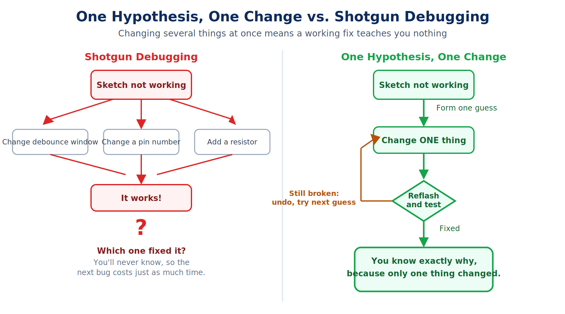
Step 3: One Hypothesis, One Change
Here's a trap almost everyone falls into at least once: the sketch isn't working, so you change the debounce window, tweak a pin number, add a resistor, and reflash all three changes at once. It starts working. Which change fixed it? You have no way to know, and the next time you hit a similar bug, you've learned nothing transferable, because you can't isolate which of your three simultaneous changes mattered.
The fix is a discipline, not a technique: form exactly one guess about what's wrong, make exactly one change to test that guess, and reflash before touching anything else. If it's still broken, that specific guess was wrong (which is real information, it rules something out), and you undo the change before trying the next guess. This feels slower in the moment. It's dramatically faster across a whole project, because every test you run tells you something real, instead of leaving you with a working sketch and no idea why.
Step 4: Instrument Instead of Guess
Part 3 already showed you Serial.print() as a way to peek at a variable's value. The systematic version of that habit is printing labeled values, consistently, at the exact moments your hypothesis says something interesting should be happening, instead of one bare number that means nothing five minutes after you printed it.
Compare Serial.println(x);, which prints a lonely number you'll have forgotten the meaning of by the next line of output, against something like this:
Serial.print(F("raw: "));
Serial.print(rawReading);
Serial.print(F("  debounced: "));
Serial.println(debouncedReading);
That second version turns your Serial Monitor into an instrument panel instead of a guessing game. You can watch two related values change together, in real time, and see exactly where they diverge from what you expected.
For analog signals specifically, the Arduino IDE has a tool built for exactly this and this series hasn't used it yet: the Serial Plotter, found right next to the Serial Monitor under Tools. Feed it plain numbers from Serial.println() (no labels this time, the Plotter wants raw numeric values on their own line) and it draws a live, scrolling graph instead of a wall of scrolling text. A noisy potentiometer reading that looks like unremarkable jitter as a column of numbers becomes an obviously spiky line on a graph, and a debounce window that's too short shows up as a visibly ragged edge instead of a number you'd have to squint at.
One gotcha worth knowing before you lean on this step too hard: adding a Serial.print() costs real time, a small delay every single call. On a sketch with tight enough timing, that small delay can be enough to change whether a race condition shows up at all. If a bug mysteriously vanishes the moment you add a print statement to investigate it, don't celebrate yet, that's often a sign the bug is timing-sensitive, not that it's fixed. Blink an LED as a lower-overhead alternative to a Serial print when you suspect this is happening.
Step 5: Verify the Fix, Don't Just Believe It
The last step is the one people skip because it feels like the hard part is already over. It isn't. "It compiled and the LED blinked once" is not the same claim as "this is fixed." Re-run your exact Step 1 repro steps, several times, including the edge cases: mash the button as fast as you physically can, not just once at a comfortable pace. Let it run for the same ten minutes that originally triggered the hang. If your fix only survives a gentle test, you haven't verified anything, you've just made the bug slightly harder to trigger.
This is also where reading error messages like a detective earns its keep, because a lot of "verified" fixes are really just a different bug wearing the first bug's symptoms. When the Arduino IDE throws a compiler or upload error, resist the urge to read only the first line and start guessing. The real information is usually in the last few lines before the error, not the first, because the compiler reports where it finally gave up, which is often several lines downstream of your actual mistake. A was not declared in this scope error on a variable you know you declared almost always means a mismatched brace or a missing semicolon above that line closed a scope early, not that the variable itself is wrong. Upload-specific errors (wrong board, wrong port, a bad USB cable, or a corrupted bootloader) are their own category entirely, worth a full reference on their own since there are a dozen board-specific variations. That deeper reference is coming as its own catalog article; for now, the troubleshooting table below covers the ones you're most likely to hit in this project.
Exercises
Bill of Materials
This part reuses Part 6's exact circuit. If you still have that counter wired up, you don't need to touch the breadboard at all, only the code changes. If you're starting fresh, here's everything again.
| Component | Description | Buy on Amazon | Buy on Temu | Buy on SparkFun | Buy on Seeed Studio |
|---|---|---|---|---|---|
| Arduino Uno | Standard microcontroller board | Amazon Link | Temu Link | SparkFun Link | Seeed Link |
| Breadboard & Jumper Wires | For prototyping connections | Amazon Link | Temu Link | SparkFun Link | Seeed Link |
| 5mm LED (×4) | Four standard through-hole LEDs for the bar-graph display | Amazon Link | Temu Link | SparkFun Link | Not yet available |
| 220Ω resistor (×4) | One current-limiting resistor per LED | Amazon Link | Temu Link | SparkFun Link | Seeed Link |
| Momentary tactile pushbutton (×2) | One wired the easy way (INPUT_PULLUP), one wired the hard way (external pull-down) | Amazon Link | Temu Link | SparkFun Link | Not yet available |
| 10kΩ fixed resistor (×1) | The pull-down resistor for the hard-wired button | Amazon Link | Temu Link | SparkFun Link | Seeed Link |
| 10kΩ potentiometer | Tunes the debounce window in real time | Amazon Link | Temu Link | SparkFun Link | Not yet available |
The products linked above may contain affiliate links. The Makers Workbench earns from qualifying purchases when these links are used.
No hardware on hand? You can still build this one. Jump to the Lab embed in the practical project section below and run this whole build right in your browser.
Exercise 1: Reproduce It Before You Touch It
- You will: Take a deliberately flaky counter and describe, precisely, the exact condition that makes it misbehave, before changing a single line of code.
- Parts: Your Part 6 counter circuit, unchanged.
- Wiring: Same as Part 6. Nothing new.
- Sketch: Load your working Part 6 sketch, but turn the potentiometer all the way to its shortest debounce setting (5ms) and leave it there for this exercise only.
- What to notice: At 5ms, the counter really does misbehave sometimes, that's the debounce window being too short to fully absorb a real button's bounce, exactly like Part 6 taught. But it doesn't misbehave on every press. Spend real time here: press slowly several times, then rapidly several times, and write down, on paper or in a note, the specific pattern where it goes wrong. "Fast presses only" is a real, testable claim. "Sometimes" is not.
- If it fails: If you can't get it to misbehave at all even at 5ms, your particular button may debounce faster than average mechanically, try pressing harder and faster, or with a fingernail instead of a fingertip for a sharper, bouncier contact.
Exercise 2: Cut the Problem in Half
- You will: Given a sketch that hangs a few seconds after boot, use bisection (commenting out half the suspect code at a time) to find which function is responsible, without reading the whole file line by line.
- Parts: Same circuit.
- Wiring: Same as Part 6.
- Sketch: Start from your working counter sketch and, for this exercise only, add this obviously-placed trap somewhere inside
loop(), without telling yourself where you put it: awhile (analogRead(POT_PIN) > 2000) { }line. Since the potentiometer never reaches above 1023, this looks harmless, but a stray typo like this (a2000where you meant200, or a condition that should never be true written so it always is) is exactly the kind of thing that's easy to write by accident and hard to spot by reading. Have a friend (or your future self, a day later) add one hidden gotcha like this into a copy of the sketch, then bisect your way to it: comment out the last half ofloop(), reflash, check if it still hangs, then narrow further. - What to notice: Each bisection step should roughly halve how much code you still need to suspect. You should find the exact line within three or four reflashes, not by reading every line, but by systematically eliminating half of what's left each time.
- If it fails: If commenting out a block breaks something else (a variable it defined is used later), stub in a placeholder value instead of deleting the whole block, so the rest of the sketch still compiles while you test.
Exercise 3: One Hypothesis, One Change
- You will: Practice changing exactly one variable at a time when tuning behavior, instead of several at once, and see directly why that discipline matters.
- Parts: Same circuit.
- Wiring: Same as Part 6.
- Sketch: Your working counter sketch. This time, try to make the counter feel more responsive at slow presses without introducing false double-counts at fast presses. You have two knobs available to you in code: the debounce window's minimum and maximum (
map(raw, 0, 1023, 5, 150), the5and150). Change only the5first (try2), reflash, and test thoroughly before touching the150at all. - What to notice: Changing one bound at a time lets you attribute any new behavior (good or bad) to that specific change with confidence. If you'd changed both bounds at once and something got worse, you'd have no way to know which one caused it.
- If it fails: If lowering the minimum to
2immediately reintroduces double-counting even at moderate press speed, that's useful, real information:2is too aggressive for your specific button, and you now know that without having touched the maximum at all.
Exercise 4: Make the Invisible Visible
- You will: Replace a single bare
Serial.println(x)debug line with labeled, structured output, then view the potentiometer's raw analog signal on the Serial Plotter to see noise you can't see in a column of numbers. - Parts: Same circuit.
- Wiring: Same as Part 6.
- Sketch: Add a temporary line inside
loop():Serial.println(analogRead(POT_PIN));(bare numbers only, no labels, since the Plotter needs plain numeric lines to graph). Open Tools > Serial Plotter instead of the Serial Monitor. - What to notice: The potentiometer's raw reading isn't perfectly smooth even when you're not touching it, small jitter of a few counts is completely normal for a 10-bit ADC (analog-to-digital converter, the hardware inside the Uno that turns a 0-5V voltage into a number from 0 to 1023) reading an unshielded wire. That jitter is invisible as scrolling text but obvious as a slightly fuzzy line on the graph. Now touch the potentiometer and watch the line move in real time.
- If it fails: If the Plotter shows a flat line at 0 or 1023 with no movement, check that the potentiometer's wiper (its center pin) is really the one wired to A0, the two outer pins go to 5V and GND and won't move at all as you turn the knob.
Exercise 5: Decode a Real Error Message
- You will: Take a genuine compiler error, read it from the bottom up instead of the top down, and correctly identify both its category (compile-time logic error, not a missing library or an upload problem) and its real cause.
- Parts: None needed, this one's pure code reading.
- Wiring: None.
- Sketch: Take your working counter sketch and delete the closing brace
}at the end ofsetup()only, then try to compile (not upload, just verify/compile is enough). - What to notice: The IDE won't point you at the missing brace directly, it can't know one is missing, only that something stopped making sense to it. It'll usually report an error several lines later, often complaining about
loop()itself, a function that you know is written correctly. That's the tell: when an error message blames code that's obviously fine, the real mistake is almost always above it, closing (or failing to close) a brace, parenthesis, or quote incorrectly. - If it fails: If your IDE's exact wording differs from what's described here, that's fine and expected, versions vary. What matters is the skill: read from the bottom of the error output upward, and treat the first place a function you know is correct gets blamed as your search boundary, not the actual mistake.
Practical Project: The Bug Hunt
Done looks like: you're handed a modified copy of Part 6's counter sketch that looks nearly identical to the working version, wired on the exact same circuit, and it has three real bugs planted in it on purpose. Using nothing but the five-step method above (not trial and error, not "I'll just try random things until it works"), you find and fix all three, and end up with a counter that behaves exactly like Part 6's did: one press, one LED, every time, across the whole range of the debounce potentiometer. A stranger reading your Serial Monitor log should be able to follow the reasoning trail for at least one of the three, not just see "fixed it" with no explanation.
What you will build
- The exact same wiring as Part 6's Reliable Two-Button Counter, unchanged.
- A modified copy of that sketch containing three bugs: one wiring/logic mismatch, one hardware/firmware conflict, and one performance bug the Part 3 checklist already trained you to suspect.
- A debugging log, printed to Serial as you go, documenting your reasoning for at least the hardest of the three bugs: what you suspected, what you changed, and what you observed.
Components needed
Everything is in the Bill of Materials above, and it's identical to Part 6's, nothing new to buy or wire.
Lab embed
Wiring
Identical to Part 6. Repeated here so this article stands on its own.
| Part | Arduino |
|---|---|
| LED 1 anode, through 220Ω resistor | D6 |
| LED 2 anode, through 220Ω resistor | D7 |
| LED 3 anode, through 220Ω resistor | D8 |
| LED 4 anode, through 220Ω resistor | D9 |
| All four LED cathodes | GND |
| Increment button, leg 1 | D2 |
| Increment button, leg 2 | GND |
| Decrement button, leg 1 | 5V |
| Decrement button, leg 2 | D3, and one leg of the 10kΩ fixed resistor |
| 10kΩ fixed resistor, other leg | GND |
| Potentiometer wiper (center pin) | A0 |
| Potentiometer outer pins | 5V and GND |
The broken sketch
This is the sketch you're handed. Somewhere in here are three real bugs. Don't read this looking for them line by line, that's exactly the instinct this whole article is trying to replace. Run the method instead: reproduce each symptom on purpose, bisect to find where it lives, form one hypothesis at a time, and instrument with Serial before you believe you've found it.
const uint8_t LED_PINS[] = {6, 7, 8, 9};                          // bar-graph array, same layout as Part 6
const uint8_t NUM_LEDS = sizeof(LED_PINS) / sizeof(LED_PINS[0]);
const uint8_t POT_PIN = A0;

// Two buttons, wired two different ways. Parallel arrays instead of separate
// variables per button, the same pattern Part 5 and Part 6 both used.
const uint8_t BTN_PINS[] = {2, 3};                                 // D2 = increment, D3 = decrement
const bool BTN_ACTIVE_LOW[] = {false, false};                      // BUG: D2 is wired INPUT_PULLUP (pressed=LOW), this should read true
const uint8_t NUM_BTNS = sizeof(BTN_PINS) / sizeof(BTN_PINS[0]);

bool lastRawPressed[NUM_BTNS] = {false, false};  // unfiltered, so it can flicker while a button bounces
bool debouncedPressed[NUM_BTNS] = {false, false};
unsigned long lastChangeTime[NUM_BTNS] = {0, 0};

uint8_t count = 0;  // clamped to 0..NUM_LEDS so the bar graph never over- or underflows
unsigned long lastPotPrint = 0;
long lastPrintedWindow = -1;  // -1 never matches a real window, so the first value always prints

void setup() {
  for (uint8_t i = 0; i < NUM_LEDS; i++) {
    pinMode(LED_PINS[i], OUTPUT);
  }
  pinMode(BTN_PINS[0], INPUT_PULLUP);   // increment button: easy way, internal pull-up
  pinMode(BTN_PINS[1], INPUT_PULLUP);   // BUG: decrement button already has an external 10k pull-down resistor.
                                         // Adding the internal pull-up here too fights that resistor.
  Serial.begin(115200);
  Serial.println(F("Counter (buggy build). Turn the pot, mash the buttons."));
  updateBarGraph();  // draw count=0 immediately instead of waiting for the first loop() pass
}

void loop() {
  unsigned long now = millis();
  unsigned long debounceMs = readDebounceWindow(now);  // re-read every pass so turning the pot takes effect live

  for (uint8_t i = 0; i < NUM_BTNS; i++) {
    // Normalize this button's raw reading into one consistent boolean, regardless of which
    // wiring style it uses underneath. Everything below this line only ever sees "pressed" or not.
    bool raw = BTN_ACTIVE_LOW[i] ? (digitalRead(BTN_PINS[i]) == LOW) : (digitalRead(BTN_PINS[i]) == HIGH);

    if (raw != lastRawPressed[i]) {        // any change at all, real press or still bouncing, resets the timer
      lastChangeTime[i] = now;
      lastRawPressed[i] = raw;
    }

    if ((now - lastChangeTime[i]) >= debounceMs && debouncedPressed[i] != lastRawPressed[i]) {
      debouncedPressed[i] = lastRawPressed[i];  // the reading has held steady for the whole window: trust it
      if (debouncedPressed[i]) {                // only act on the confirmed press edge, not the release
        if (i == 0 && count < NUM_LEDS) {  // check the bound first: count is unsigned, so 0 - 1 would wrap to 255
          count++;
        }
        if (i == 1 && count > 0) {
          count--;
        }
        updateBarGraph();
        Serial.print(F("count: "));
        Serial.println(count);
      }
    }
    delay(15);  // BUG: added "temporarily" to make Serial output easier to read while this was written, never removed
  }
}

unsigned long readDebounceWindow(unsigned long now) {
  int raw = analogRead(POT_PIN);
  long windowMs = map(raw, 0, 1023, 5, 150);            // deliberately wide range: 5ms is too short, 150ms is too long
  windowMs = constrain(windowMs, 5, 150);
  if (now - lastPotPrint >= 250 && windowMs != lastPrintedWindow) {  // print at most 4x/sec, only on real change
    lastPotPrint = now;
    lastPrintedWindow = windowMs;
    Serial.print(F("debounce window: "));
    Serial.print(windowMs);
    Serial.println(F("ms"));
  }
  return (unsigned long)windowMs;
}

void updateBarGraph() {
  for (uint8_t i = 0; i < NUM_LEDS; i++) {
    digitalWrite(LED_PINS[i], i < count ? HIGH : LOW);
  }
}
I've marked each bug with a // BUG: comment above so you can check your own findings against them once you've done the hunt honestly. Cover them up (or better, have someone else strip the comments before handing you the file) if you want the full, unspoiled exercise.
Applying the method
Bug 1, the delay(): Step 1 first. Load the sketch and just use it for thirty seconds. It feels sluggish, noticeably laggier than Part 6's version, even with the potentiometer turned to its shortest setting. That's your reproduction: "always laggy, regardless of pot position," not intermittent at all. Part 3's basic checklist already told you where to look for exactly this symptom: search the sketch for delay(. There it is, sitting at the bottom of the button loop, delay(15), a leftover the fictional author of this sketch added "temporarily" to slow the loop down enough to read Serial output comfortably, and never removed. Removing it is the whole fix. This is deliberately the easiest of the three, the checklist-level bug, included so you can feel the difference between "the fast checklist catches this in ten seconds" and the two bugs still ahead of you, which it won't.
Bug 2, the inverted button: Step 1, then Step 4. Press the increment button. Nothing happens, or worse, the count seems to already be climbing before you've pressed anything. That's your reproduction: the increment button behaves as if it's always pressed. Instrument before guessing: add a print of the raw digitalRead(BTN_PINS[0]) value inside the loop and watch it in the Serial Monitor. You'll see it reads LOW at rest and HIGH when pressed, the opposite of what INPUT_PULLUP wiring should produce (LOW when pressed, HIGH at rest). That's the concrete evidence, not a guess. Now check the Wiring table against the code, signal by signal, exactly the Hard Rule this whole series holds every project to: the table says D2 is wired INPUT_PULLUP, meaning pressed equals LOW. The code's BTN_ACTIVE_LOW[] array has false in that slot, meaning the code assumes pressed equals HIGH. Table and code disagree. Flip that one entry to true and retest.
Bug 3, the pull-up/pull-down conflict: Step 2, then Step 3. Once the first two fixes are in, the decrement button (D3) still behaves erratically, sometimes triggering on a light touch, sometimes needing a hard, deliberate press, never consistent. This is the hardest of the three because it isn't purely a code bug, it's a code decision fighting a hardware decision. Bisect: is it the code or the wiring? Swap in the increment button's exact wiring style for a moment (temporarily rewire D3 to skip the external pull-down and use INPUT_PULLUP only, matching D2). If the erratic behavior disappears entirely when you do that, the code and the original wiring were never going to agree, no amount of debounce tuning fixes a fight between two pull mechanisms pulling in opposite directions. Form one hypothesis: setup()'s pinMode(BTN_PINS[1], INPUT_PULLUP) is wrong for a pin that already has a physical 10kΩ pull-down resistor wired to it. Change exactly that one line, from INPUT_PULLUP back to plain INPUT (letting the external resistor do the only pulling), and nothing else. Reflash. Verify per Step 5: mash the decrement button as fast as you can for a solid thirty seconds, not just once gently.
The fixed sketch
Once all three fixes are applied, correctly, you're back to Part 6's exact working sketch:
const uint8_t LED_PINS[] = {6, 7, 8, 9};                          // bar-graph array, same layout as Part 5 and 6
const uint8_t NUM_LEDS = sizeof(LED_PINS) / sizeof(LED_PINS[0]);
const uint8_t POT_PIN = A0;

// Two buttons, wired two different ways. Parallel arrays instead of separate
// variables per button, the same pattern Part 5 and Part 6 both used.
const uint8_t BTN_PINS[] = {2, 3};                                 // D2 = increment, D3 = decrement
const bool BTN_ACTIVE_LOW[] = {true, false};                       // FIXED: D2 is INPUT_PULLUP (pressed=LOW); D3 is external pull-down (pressed=HIGH)
const uint8_t NUM_BTNS = sizeof(BTN_PINS) / sizeof(BTN_PINS[0]);

bool lastRawPressed[NUM_BTNS] = {false, false};  // unfiltered, so it can flicker while a button bounces
bool debouncedPressed[NUM_BTNS] = {false, false};
unsigned long lastChangeTime[NUM_BTNS] = {0, 0};

uint8_t count = 0;  // clamped to 0..NUM_LEDS so the bar graph never over- or underflows
unsigned long lastPotPrint = 0;
long lastPrintedWindow = -1;  // -1 never matches a real window, so the first value always prints

void setup() {
  for (uint8_t i = 0; i < NUM_LEDS; i++) {
    pinMode(LED_PINS[i], OUTPUT);
  }
  pinMode(BTN_PINS[0], INPUT_PULLUP);  // increment button: easy way, internal pull-up
  pinMode(BTN_PINS[1], INPUT);         // FIXED: decrement button relies on its external pull-down resistor only
  Serial.begin(115200);
  Serial.println(F("Counter (fixed). Turn the pot, mash the buttons."));
  updateBarGraph();  // draw count=0 immediately instead of waiting for the first loop() pass
}

void loop() {
  unsigned long now = millis();
  unsigned long debounceMs = readDebounceWindow(now);  // re-read every pass so turning the pot takes effect live

  for (uint8_t i = 0; i < NUM_BTNS; i++) {
    // Normalize this button's raw reading into one consistent boolean, regardless of which
    // wiring style it uses underneath. Everything below this line only ever sees "pressed" or not.
    bool raw = BTN_ACTIVE_LOW[i] ? (digitalRead(BTN_PINS[i]) == LOW) : (digitalRead(BTN_PINS[i]) == HIGH);

    if (raw != lastRawPressed[i]) {        // any change at all, real press or still bouncing, resets the timer
      lastChangeTime[i] = now;
      lastRawPressed[i] = raw;
    }

    if ((now - lastChangeTime[i]) >= debounceMs && debouncedPressed[i] != lastRawPressed[i]) {
      debouncedPressed[i] = lastRawPressed[i];  // the reading has held steady for the whole window: trust it
      if (debouncedPressed[i]) {                // only act on the confirmed press edge, not the release
        if (i == 0 && count < NUM_LEDS) {  // check the bound first: count is unsigned, so 0 - 1 would wrap to 255
          count++;
        }
        if (i == 1 && count > 0) {
          count--;
        }
        updateBarGraph();
        Serial.print(F("count: "));
        Serial.println(count);
      }
    }
    // FIXED: no delay() here at all. The loop runs as fast as the board can manage,
    // exactly what Part 4 taught you to expect from clean millis()-based timing.
  }
}

unsigned long readDebounceWindow(unsigned long now) {
  int raw = analogRead(POT_PIN);
  long windowMs = map(raw, 0, 1023, 5, 150);            // deliberately wide range: 5ms is too short, 150ms is too long
  windowMs = constrain(windowMs, 5, 150);
  if (now - lastPotPrint >= 250 && windowMs != lastPrintedWindow) {  // print at most 4x/sec, only on real change
    lastPotPrint = now;
    lastPrintedWindow = windowMs;
    Serial.print(F("debounce window: "));
    Serial.print(windowMs);
    Serial.println(F("ms"));
  }
  return (unsigned long)windowMs;
}

void updateBarGraph() {
  for (uint8_t i = 0; i < NUM_LEDS; i++) {
    digitalWrite(LED_PINS[i], i < count ? HIGH : LOW);
  }
}
Every pin const above matches the Wiring table row for that signal: LED_PINS[] is 6, 7, 8, 9. BTN_PINS[] is 2 (increment) then 3 (decrement). POT_PIN is A0. Checked signal by signal, both directions, same as every project in this series.
If the project fails the "done" test
Still laggy after removing the delay(15): check you removed it from inside the for loop and not just commented it out, a commented line still needs its own line but does nothing, so this shouldn't trip you up, but double check you reflashed after the edit. Increment button still seems inverted: confirm you changed the BTN_ACTIVE_LOW[] array's first entry, not the second, array indices are easy to swap by accident. Decrement button still erratic after fixing the pinMode(): verify with a multimeter (or just careful visual inspection) that the external 10kΩ resistor is wired between D3 and GND as the Wiring table specifies, not floating or connected to the wrong rail, a truly missing resistor looks identical in symptom to the pull-up/pull-down conflict this bug was built around.
Troubleshooting
| Symptom | Cause | Fix |
|---|---|---|
| Bug disappears when Serial Monitor is open, comes back when closed | Serial prints cost real time; a timing-sensitive (race condition) bug can hide behind that extra delay | Don't trust a fix you only verified with Serial open. Blink an LED instead of printing when timing is tight, then re-verify with Serial closed |
| Fixed one thing, two new things broke | Changed multiple variables in one test (Step 3 skipped) | Revert to the last known-good version, then change exactly one thing and retest before changing anything else |
| Can't reproduce it a second time | Loose jumper wire or a marginal breadboard connection, not a code bug at all | Reseat every jumper, press each one firmly into its row, and retest before assuming the code is at fault |
| Compiler blames a line you know is correct | A brace, parenthesis, or quote was left unclosed somewhere above it | Read the error from the bottom up, and treat the first mention of code you trust as your search boundary, not your answer |
| Upload fails partway through or times out | Wrong board/port selected, or a charge-only USB cable with no data lines | Check Tools > Board and Tools > Port match your actual hardware; swap to a known data-capable USB cable. A full board/port/bootloader reference is coming as its own catalog article |
| Values jump or flicker with nothing touching the board | A digital input pin left floating, with no pull-up or pull-down defined | Confirm every input pin's pinMode() call matches what the Wiring table says it needs, INPUT_PULLUP or a real external resistor, never neither |
| Two debug prints show sensible values individually but you still can't spot the problem | Bare, unlabeled Serial.println() calls, hard to tell which number is which once several are scrolling by | Label every debug print ("raw: ", "debounced: ") so the output tells its own story without you having to remember the code |
Where This Fits in the Series
You now have an actual repeatable method for the bugs that survive Part 3's fast checklist: reproduce it on purpose, cut the problem in half, change one thing at a time, instrument before you guess, and verify the fix instead of just believing it. That's a skill that transfers to literally every project in this series from here forward, and to code and hardware outside it entirely.
Series: Previous part, Part 6: Digital I/O You Can Trust. This part, Part 7: Systematic Debugging. Next part, Part 8: Interrupts, Reacting Without Polling.
Catalog: The I²C Scanner is a perfect example of Step 2 (isolating hardware from firmware) applied to a specific bus, run it before assuming any I²C sensor's library is broken. A dedicated upload-error quick-reference card (board/port/baud/bootloader, symptom by symptom) is planned as its own catalog article for when you need the exhaustive version of this article's troubleshooting table.
Wrap-Up and What's Next
Debugging isn't a talent some people have and others don't, it's five steps, run in order, on purpose: reproduce it, cut it in half, change one thing at a time, instrument instead of guess, and verify the fix instead of just believing it. Part 3's checklist still catches the easy ones fast. This method is for everything that checklist doesn't catch, and it works exactly the same whether the bug is in your code, your wiring, or the uncomfortable place where the two disagree with each other.
Next up, Part 8: Interrupts, Reacting Without Polling, where you'll learn attachInterrupt(), keeping an interrupt service routine short and fast, and why a variable shared with one needs to be marked volatile, so your sketch can react to a fast event instead of hoping it catches it in time.
Want to go deeper? Download the full eBook once the series is complete, and subscribe for the rest of the Arduino Mastery Series.
Hack The World and Make Awesome.