Part 7 ended by pointing here: your sketch needs a way to react to a fast event instead of hoping it catches it in time. Its debugging method also gives us the right way to prove the failure before we fix it: reproduce it, instrument it, and compare the results. A signal goes HIGH and LOW while your sketch is busy somewhere else. By the time loop() checks the pin again, the signal is already back where it started. The code reads a perfectly ordinary LOW and never learns that anything happened.
That is the limit of polling, which means repeatedly asking an input for its current state. Polling is not bad. It is exactly right for plenty of jobs, including a button that stays pressed for a tenth of a second while loop() runs thousands of times. It becomes unreliable when an event can begin and end between two checks, or when every edge must be counted even while the main sketch is doing other work. Part 8 is about recognizing that boundary instead of reaching for an interrupt every time you see an input pin.
We will use Uno and classic Nano pin numbers, with D2 as the interrupt input, D9 as a clean pulse source, and D4 as a slow button that remains polled on purpose. By the end, you will build a Polling Versus Interrupt Pulse Monitor. It sends the same signal, roughly 490 cycles per second, to a polling counter and an interrupt counter, then adds a controlled workload so you can watch polling miss events while the interrupt keeps catching them. Along the way, you will learn the full attachInterrupt() call, the RISING, FALLING, CHANGE, and LOW modes, how to keep an interrupt service routine short, and what volatile does and does not guarantee.
What Does Polling Miss?
Think about checking the front porch for a package. If you look through the window once every minute and the box stays there until you pick it up, polling works perfectly. You can miss the exact instant the driver arrived and still see the package on the next check. Now change the event. Someone taps the doorbell button for a tenth of a second and leaves. If you only look at the button once a minute, every check can show “not pressed” even though a real press happened between checks.
A digital input works the same way. digitalRead() tells you the pin’s state at the instant you call it. It does not give you a history of what the pin did since the previous call. If the signal went LOW to HIGH to LOW while loop() was updating a display, sending Serial data, or working through a long calculation, the next digitalRead() only sees LOW. The pulse has vanished from the sketch’s point of view.
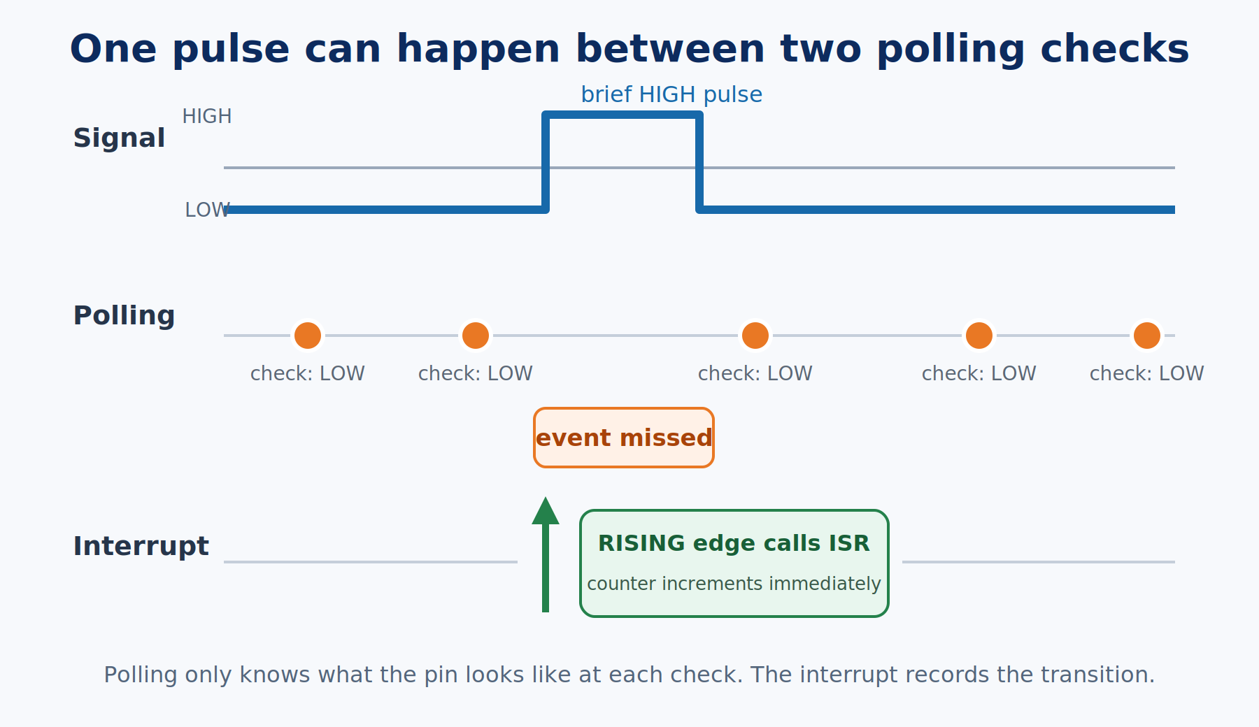
The important comparison is not “polling versus interrupts” as if one is primitive and the other is advanced. The useful comparison is the event’s shortest meaningful duration against the longest gap between checks. Polling is fine when the event lasts comfortably longer than that gap, or when you only care about the current level. An interrupt earns its complexity when a brief event can fit entirely inside the gap, every edge matters, or the response has a deadline your normal loop() cannot promise.
| Situation | Usually use | Why |
|---|---|---|
| A button is held while a menu remains open | Polling | The human action lasts a long time compared with a normal loop pass, and the current level is what matters |
| A potentiometer controls brightness | Polling | You want the latest value, not a record of every tiny change between readings |
| A sensor emits one short pulse per wheel revolution | Interrupt | Each pulse represents real distance or speed, so a missed edge corrupts the measurement |
| A rotary encoder can turn while the sketch updates a display | Interrupt or a proven encoder library | Fast transitions can occur while normal code is busy, and direction depends on their order |
| A signal stays LOW until your code acknowledges it | Polling may be enough | The event remains visible, so the next check can still find it |
There is one more practical reason not to attach interrupts to everything: interrupt code has stricter rules, and every interrupt briefly pauses the normal program. A slow button that polling already reads reliably does not improve just because it can interrupt the processor. In this chapter’s project, D4 is that slow button. D2 carries the fast pulse stream. Each input gets the simpler tool that honestly fits its job.
How Does an Arduino Interrupt Work?
An external interrupt is the microcontroller’s doorbell. Normal code can be halfway through another task when the electrical condition on an interrupt-capable pin occurs. The chip finishes its current machine instruction, remembers where it was, and jumps to a special function you registered for that event. That function is an interrupt service routine, usually shortened to ISR. When the ISR returns, the chip resumes the interrupted code.
The Arduino is not running two pieces of your sketch at the same time. The ISR temporarily takes control from loop(). That is why speed matters. A short ISR records what happened and gets out. A long ISR holds the rest of the sketch still, delays other interrupts, and can lose incoming Serial data. On a classic Uno, the timing behind millis() also depends on an interrupt. Its value does not advance while your ISR is running, and delay() cannot work normally there.
Under the friendly Arduino function, the ATmega328P has interrupt-control bits, enable bits, and fixed interrupt vectors, which are small addresses that tell the chip where each ISR begins. You could configure those registers yourself, but then your sketch would be tied tightly to that one microcontroller. attachInterrupt() handles that setup through the Arduino core and keeps the intent readable.
On an Uno or classic ATmega328P Nano, only D2 and D3 support the external interrupts used by attachInterrupt(). Other board families expose different pins, sometimes many more. That is why the recommended call passes the pin through digitalPinToInterrupt() instead of assuming that a pin number and an internal interrupt number are the same.
attachInterrupt(
  digitalPinToInterrupt(PULSE_INPUT_PIN), // Translate the Arduino pin into this board's interrupt number.
  countPulseISR,                          // Name the no-argument, no-return function to run for the event.
  RISING                                  // Trigger when the signal changes from LOW to HIGH.
);
The function returns nothing. The ISR named in the second argument must take no parameters and return no value, so its declaration looks like void countPulseISR(). The third argument chooses the electrical condition that rings the doorbell.
For the official syntax and the current board-by-board pin table, keep Arduino’s attachInterrupt() reference nearby. This article stays on the Uno/Nano path so you can see one complete pattern without mixing several microcontroller families together.
What Do RISING, FALLING, CHANGE, and LOW Mean?
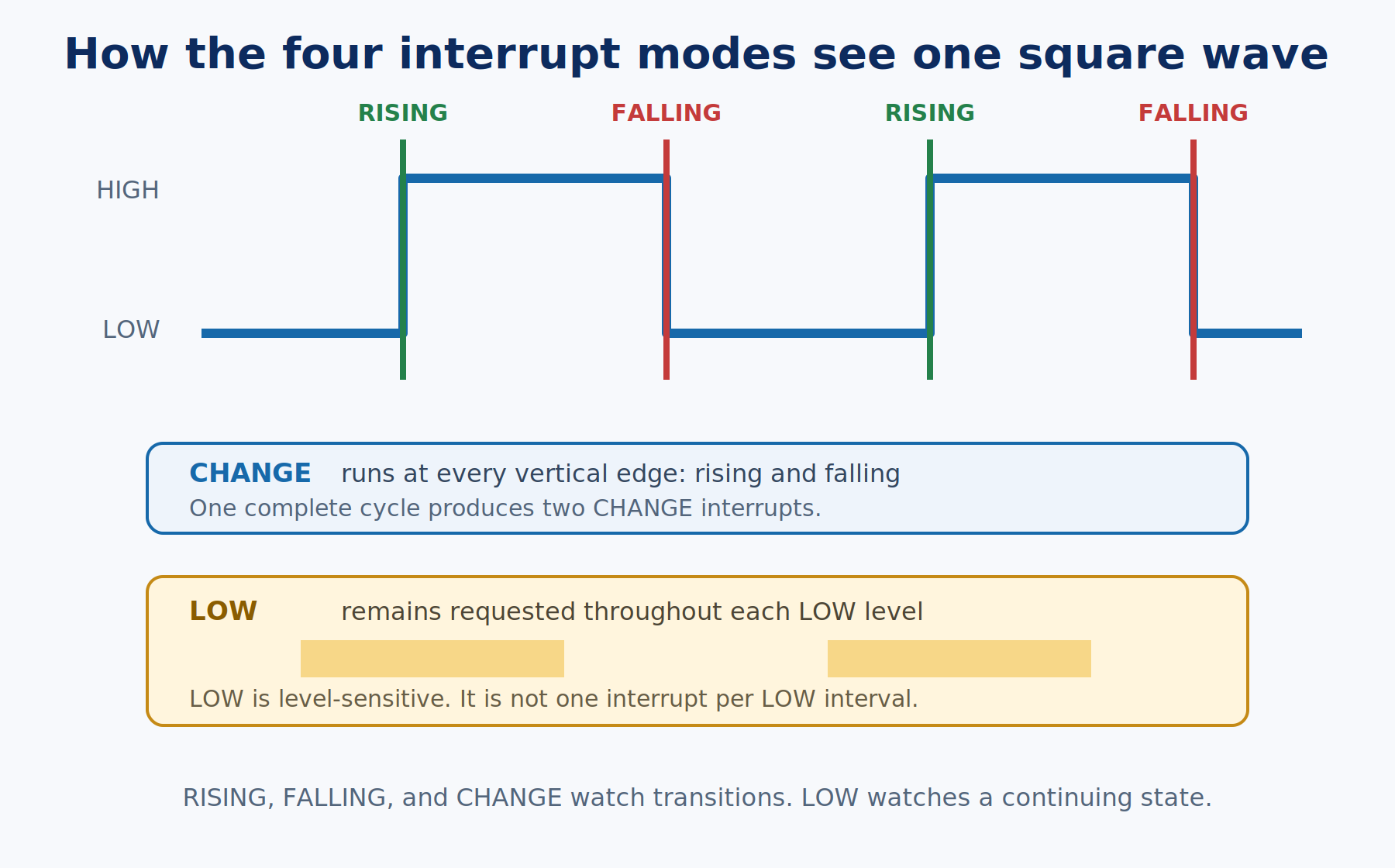
An edge is the transition between the two digital levels. A rising edge is the instant a signal moves from LOW to HIGH. A falling edge is the opposite transition. A level is a state that can remain true for a stretch of time. This distinction matters because three Arduino interrupt modes watch transitions, while LOW watches a continuing state.
| Mode | Triggers when | Good fit | Common mistake |
|---|---|---|---|
RISING | LOW changes to HIGH | Count one positive pulse edge, such as the start of a tachometer pulse | Expecting it to run again while the signal remains HIGH |
FALLING | HIGH changes to LOW | Detect an active-low sensor event or an INPUT_PULLUP button press | Forgetting that a bouncing button can create several falling edges |
CHANGE | Either edge occurs | Measure both halves of a pulse or watch both transitions of an encoder channel | Forgetting that one complete square-wave cycle produces two interrupts |
LOW | The pin is LOW | Level-sensitive hardware, including some wake-up arrangements | Treating it like one event; the ISR can be requested again as long as the pin stays LOW |
Our D9 pulse-width modulation (PWM) signal makes the difference easy to predict. PWM is a hardware-generated rectangular wave that controls an output by changing how much of each cycle it spends HIGH. The value 128 gives this test signal an approximately 50 percent duty cycle, meaning it spends about half its time HIGH and half LOW. On an Uno or classic Nano, D9 repeats that cycle roughly 490 times per second with the default timer settings. RISING should count roughly 490 events per second, and FALLING should do the same. CHANGE sees both edges and should land near 980. Those numbers are approximate because the report itself takes time and the one-second software window will not line up perfectly with the hardware waveform.
LOW is not another way to count one pulse. While the input remains LOW, the interrupt request remains active. After the ISR returns and interrupts are allowed again, the same LOW level can request service again. That behavior is useful when hardware promises to hold a request active until software handles it. It is a poor fit for this edge counter, and it can consume most of the processor if the line is held LOW without a plan to clear or disable the source.
A classic AVR Uno does not offer HIGH as an attachInterrupt() mode. Some other Arduino boards do. That is a board-specific extension, not one of the four portable modes this chapter teaches.
What Belongs Inside an ISR?
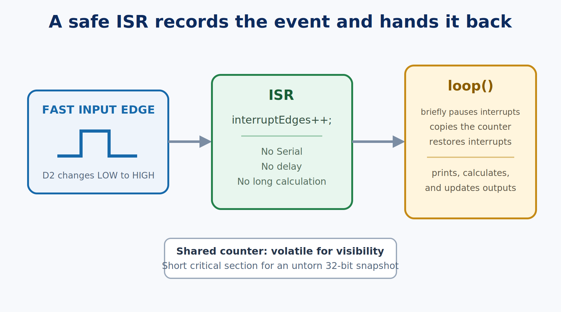
The safest mental model is a person at the door taking one note: “a pulse happened.” They do not invite the visitor inside, prepare dinner, update a display, and write a log entry before letting anyone else use the hallway. Your ISR should set a flag, increment a counter, or copy one already-available hardware value. Then it should return.
Keep these out of a beginner ISR:
Serial.print(), because Serial transmission uses buffering and interrupts of its owndelay(), because it depends on interrupt-driven timing and will not behave normally- long loops, floating-point calculations, display updates, and sensor transactions
- debounce logic that tries to do a whole button workflow inside the ISR
A mechanical button still bounces when connected to an interrupt pin. The interrupt does not clean the signal. It only reacts faster to every dirty edge, which can make the bounce more obvious. Part 6 is still the source of truth for pull resistors and debounce. The existing comprehensive external-interrupt guide goes further into interrupt-driven button debounce, cross-board pin availability, sleep/wake uses, and several application examples. Part 8 keeps the signal clean so we can isolate the polling question.
Why Does an ISR Variable Need volatile?
A compiler is allowed to optimize code when it can prove that ordinary program flow does not change a value. Suppose loop() keeps checking a global counter, but nothing in the visible path through loop() writes that counter. An optimizer may reuse a value it already loaded instead of returning to memory every time. The ISR is outside that normal flow. It can change the counter between any two ordinary instructions.
The volatile keyword tells the compiler that a value may change unexpectedly, so every read and write must really touch memory. That is why the project declares volatile uint32_t interruptEdges. A uint32_t is an unsigned 32-bit integer, a whole-number type with enough room for more than four billion counted events before it wraps back to zero. The ISR updates it, and normal code reads it.
volatile does not make a multi-byte operation indivisible. The Uno’s ATmega328P is an 8-bit processor. Reading a 32-bit uint32_t takes several smaller steps. An interrupt can occur between those steps, leaving normal code with some bytes from the old value and some from the new one. That mixed result is called a torn read.
The fix is a very short critical section, a small stretch of normal code that the ISR is temporarily prevented from interrupting:
noInterrupts();  // an 8-bit AVR copies 32 bits in several steps; keep the ISR from changing the value mid-copy
uint32_t edgeSnapshot = interruptEdges;
interruptEdges = 0;  // reset in the same protected section so no edge slips between copy and reset
interrupts();  // keep this window short: no interrupts run while it is off
Serial.println(edgeSnapshot);  // print the copy, never the shared variable
Keep that protected section as small as possible. Copy and reset the shared data, restore interrupts, then print or calculate with the private snapshot. In this chapter’s sketches, only the ISR increments interruptEdges, and normal code only touches it inside that protected block. That ownership rule is just as important as the keyword.
Exercises
Bill of Materials
This chapter needs very little hardware. The Uno creates its own test pulses on D9, so one jumper wire can feed them straight back into D2. The pushbutton only turns the simulated workload on and off. It is deliberately not the interrupt source, because a mechanical button is slow enough to poll and bouncy enough to distract from the fast-event lesson.
| Component | Description | Buy on Amazon | Buy on Temu | Buy on SparkFun | Buy on Seeed Studio |
|---|---|---|---|---|---|
| Arduino Uno | Standard ATmega328P-based board used for every pin and timing example in this chapter | Amazon Link | Temu Link | SparkFun Link | Seeed Link |
| Breadboard & Jumper Wires | A breadboard for the button and one male-to-male jumper from D9 to D2 | Amazon Link | Temu Link | SparkFun Link | Seeed Link |
| Momentary tactile pushbutton | A normally-open button held to enable the project’s simulated workload | Amazon Link | Temu Link | SparkFun Link | Not yet available |
The products linked above may contain affiliate links. The Makers Workbench earns from qualifying purchases when these links are used.
No hardware on hand? You can still build this one. Jump to the Lab embed in the practical project section below and run this whole build right in your browser.
Before wiring: remove the Part 6/7 increment button from D2 if that circuit is still on your breadboard. The Uno only has two true external-interrupt pins, D2 and D3, and this chapter reserves D2 for the fast pulse signal. The slow workload button moves to D4 so it cannot fight the interrupt input.
Exercise 1: Poll a Slow, Held Input
- You will: Poll a button on D4 and mirror its held state on the built-in LED, proving that polling is completely appropriate when an event remains visible for a long time.
- Parts: Arduino Uno, breadboard, jumper wires, and one momentary pushbutton from the Bill of Materials.
- Wiring: Connect one side of the button to D4 and the other side to GND. The sketch uses
INPUT_PULLUP, so no external resistor is required. - Sketch:
const uint8_t BUTTON_PIN = 4;  // slow human input, so polling is plenty
const uint8_t STATUS_LED_PIN = LED_BUILTIN;  // the Uno's onboard LED (D13)

void setup() {
  pinMode(BUTTON_PIN, INPUT_PULLUP);  // button to GND, so pressed reads LOW
  pinMode(STATUS_LED_PIN, OUTPUT);
  Serial.begin(115200);
  Serial.println(F("Exercise 1: polling a slow, held input."));
}

void loop() {
  bool buttonIsHeld = digitalRead(BUTTON_PIN) == LOW;
  digitalWrite(STATUS_LED_PIN, buttonIsHeld ? HIGH : LOW);
}- What to notice: The LED follows the button without an interrupt. Contact bounce may happen at the instant of a press, but this sketch only cares whether the button is held right now. It does not count edges, so the brief chatter has no visible consequence.
- If it fails: If the LED stays on, the D4 side of the button is probably tied to GND all the time. Rotate the tactile button 90 degrees or check which legs are internally paired.
Exercise 2: Count a Fast Signal by Polling
- You will: Generate a clean PWM pulse stream on D9, loop it into D2, and count rising edges by repeatedly sampling the input.
- Parts: Arduino Uno and one male-to-male jumper wire. Leave the D4 button in place for the project.
- Wiring: Connect D9 directly to D2. Both pins belong to the same 5V board, so they already share ground. Do not connect D9 to 5V or GND.
- Sketch:
const uint8_t PULSE_OUTPUT_PIN = 9;  // D9's roughly 490 Hz PWM is the test signal
const uint8_t PULSE_INPUT_PIN = 2;  // jumpered to D9
const unsigned long REPORT_MS = 1000;

bool lastSignalState = LOW;  // remembered so we can spot a LOW-to-HIGH change
uint32_t polledEdges = 0;
unsigned long lastReportTime = 0;

void setup() {
  pinMode(PULSE_OUTPUT_PIN, OUTPUT);
  pinMode(PULSE_INPUT_PIN, INPUT);  // D9 drives this pin, so no pull-up is needed
  analogWrite(PULSE_OUTPUT_PIN, 128);  // 128 of 255 is a 50% duty cycle
  Serial.begin(115200);
  Serial.println(F("Exercise 2: counting PWM edges by polling."));
}

void loop() {
  bool signalState = digitalRead(PULSE_INPUT_PIN);

  if (signalState == HIGH && lastSignalState == LOW) {  // count the transition, not the level, or one pulse would count many times
    polledEdges++;
  }
  lastSignalState = signalState;

  unsigned long now = millis();
  if (now - lastReportTime >= REPORT_MS) {
    Serial.print(F("polled rising edges per second: "));
    Serial.println(polledEdges);
    polledEdges = 0;
    lastReportTime = now;
  }
}- What to notice: With almost nothing else in
loop(), polling should find close to 490 rising edges per second. It may miss a few while Serial output is transmitted. That result is not proof that polling is universally safe. It only proves this loop is currently fast enough for this signal. - If it fails: A count of zero usually means the D9-to-D2 jumper is missing or one end is in the wrong header socket. A count near 980 means you changed the edge test and started counting both transitions.
Exercise 3: Attach the First Interrupt
- You will: Move edge counting into a minimal ISR, mark the shared counter
volatile, and copy that 32-bit count safely before printing it. - Parts: Same D9-to-D2 jumper as Exercise 2.
- Wiring: Unchanged. D9 remains the pulse output and D2 remains the interrupt input.
- Sketch:
const uint8_t PULSE_OUTPUT_PIN = 9;  // D9's roughly 490 Hz PWM is the test signal
const uint8_t PULSE_INPUT_PIN = 2;  // D2 is one of the Uno's two external-interrupt pins
const unsigned long REPORT_MS = 1000;

volatile uint32_t interruptEdges = 0;  // volatile: the ISR changes this behind loop()'s back, so loop() must re-read it from memory
unsigned long lastReportTime = 0;

void setup() {
  pinMode(PULSE_OUTPUT_PIN, OUTPUT);
  pinMode(PULSE_INPUT_PIN, INPUT);  // D9 drives this pin, so no pull-up is needed
  analogWrite(PULSE_OUTPUT_PIN, 128);  // 128 of 255 is a 50% duty cycle
  attachInterrupt(digitalPinToInterrupt(PULSE_INPUT_PIN), countPulseISR, RISING);  // RISING: one call per LOW-to-HIGH edge
  Serial.begin(115200);
  Serial.println(F("Exercise 3: counting PWM edges with an interrupt."));
}

void loop() {
  unsigned long now = millis();
  if (now - lastReportTime >= REPORT_MS) {
    noInterrupts();  // copying 32 bits takes several steps on an 8-bit AVR, so block the ISR meanwhile
    uint32_t edgeSnapshot = interruptEdges;
    interruptEdges = 0;  // reset in the same protected section so no edge is lost
    interrupts();

    Serial.print(F("interrupt rising edges per second: "));
    Serial.println(edgeSnapshot);  // print outside the critical section, because Serial is slow
    lastReportTime = now;
  }
}

void countPulseISR() {
  interruptEdges++;  // keep the ISR tiny: count and get out
}- What to notice: The ISR contains one meaningful line. Serial output, timing, copying, and resetting all happen in
loop(). The result should stay close to 490 rising edges per second. - If it fails: If the sketch compiles but reports zero, confirm the first
attachInterrupt()argument isdigitalPinToInterrupt(PULSE_INPUT_PIN), not the literal pin number used as an interrupt number.
Exercise 4: Change the Trigger Mode
- You will: Change one named trigger-mode constant and predict the count before uploading.
- Parts: Same circuit.
- Wiring: Unchanged.
- Sketch: Upload the complete sketch below once with
TRIGGER_MODEset toRISING, once with it set toFALLING, and once with it set toCHANGE. Change exactly that one word per test. Do not useLOWfor this continuous counter, because the signal remains LOW for roughly half of every cycle and can request the ISR repeatedly during that level.
const uint8_t PULSE_OUTPUT_PIN = 9;  // D9's roughly 490 Hz PWM is the test signal
const uint8_t PULSE_INPUT_PIN = 2;  // D2 is one of the Uno's two external-interrupt pins
const unsigned long REPORT_MS = 1000;
const int TRIGGER_MODE = RISING;  // swap RISING for FALLING or CHANGE between tests

volatile uint32_t interruptEdges = 0;  // volatile: the ISR changes this behind loop()'s back, so loop() must re-read it from memory
unsigned long lastReportTime = 0;

void setup() {
  pinMode(PULSE_OUTPUT_PIN, OUTPUT);
  pinMode(PULSE_INPUT_PIN, INPUT);  // D9 drives this pin, so no pull-up is needed
  analogWrite(PULSE_OUTPUT_PIN, 128);  // 128 of 255 is a 50% duty cycle
  attachInterrupt(digitalPinToInterrupt(PULSE_INPUT_PIN), countPulseISR, TRIGGER_MODE);  // same ISR, different edge rule
  Serial.begin(115200);
  Serial.println(F("Exercise 4: change TRIGGER_MODE, upload, and compare."));
}

void loop() {
  unsigned long now = millis();
  if (now - lastReportTime >= REPORT_MS) {
    noInterrupts();  // copying 32 bits takes several steps on an 8-bit AVR, so block the ISR meanwhile
    uint32_t edgeSnapshot = interruptEdges;
    interruptEdges = 0;  // reset in the same protected section so no edge is lost
    interrupts();

    Serial.print(F("interrupt events per second: "));
    Serial.println(edgeSnapshot);  // print outside the critical section, because Serial is slow
    lastReportTime = now;
  }
}

void countPulseISR() {
  interruptEdges++;  // keep the ISR tiny: count and get out
}- What to notice:
RISINGandFALLINGshould each report close to 490 events per second.CHANGEshould report close to 980 because every cycle contains two edges. - If it fails: If all three tests produce roughly the same count, make sure you uploaded after each one-word change and that the Serial Monitor reconnected to the new sketch.
You now have every piece the practical project needs: a slow input that polling handles honestly, a repeatable fast signal, a polling edge detector, a minimal ISR, and a safe handoff from ISR-owned data to normal code.
Practical Project: Polling Versus Interrupt Pulse Monitor
Done looks like: release the D4 button and watch the Serial Monitor. The interrupt and polling rates should both sit near the D9 source rate of roughly 490 rising edges per second. Hold D4 to enable the workload. The interrupt rate should remain near 490 while the polling rate falls sharply, often below 200. Release the button and the polling rate should recover. The built-in LED keeps blinking as a visible reminder that normal loop() work continues around both measurements.
What You Will Build
- A roughly 490 Hz hardware PWM pulse source on D9, looped into interrupt pin D2
- Two counters watching the same signal, one sampled by
loop()and one updated by an ISR - A slow D4 button that remains polled because holding a human-speed level does not need an interrupt
- A repeatable six-millisecond synthetic workload that exposes the gap between polling checks
- A non-blocking heartbeat on the Uno’s built-in LED and a compact one-line Serial report
Components Needed
Everything is in the Bill of Materials above: an Arduino Uno, breadboard and jumper wires, and one tactile pushbutton. The status LED is already built into the board.
Lab Embed
Wiring
| Part | Arduino |
|---|---|
| Jumper wire, one end | D9 (the PWM pulse output) |
| Jumper wire, other end | D2 (the interrupt input) |
| Workload button, leg 1 | D4 |
| Workload button, leg 2 | GND |
| Status LED | Built-in LED on D13 (LED_BUILTIN on the Uno), nothing to wire |
Check this before powering the board: D9 must connect to D2, not to the 5V or GND header. Both D9 and D2 are digital pins on the same board, so the direct jumper is safe. A D9-to-GND connection would short the output whenever PWM drives it HIGH.
The Sketch
const uint8_t PULSE_OUTPUT_PIN = 9;  // D9's roughly 490 Hz PWM is the test signal
const uint8_t PULSE_INPUT_PIN = 2;  // D2 has the external interrupt, jumpered to D9
const uint8_t WORKLOAD_BUTTON_PIN = 4;  // held to GND when pressed; polled because a human hold is slow
const uint8_t STATUS_LED_PIN = LED_BUILTIN;  // onboard LED, shows the loop is still alive

const unsigned long REPORT_MS = 1000;
const unsigned long HEARTBEAT_MS = 250;
const unsigned long WORKLOAD_US = 6000;  // 6 ms spans about three PWM cycles (2 ms each), so polling misses edges

volatile uint32_t interruptEdges = 0;  // volatile: changed by the ISR, read by loop()
uint32_t polledEdges = 0;  // only loop() touches this one, so no volatile or locking
bool lastSignalState = LOW;

unsigned long lastReportTime = 0;
unsigned long lastHeartbeatTime = 0;
bool heartbeatState = LOW;

void setup() {
  pinMode(PULSE_OUTPUT_PIN, OUTPUT);
  pinMode(PULSE_INPUT_PIN, INPUT);
  pinMode(WORKLOAD_BUTTON_PIN, INPUT_PULLUP);
  pinMode(STATUS_LED_PIN, OUTPUT);

  analogWrite(PULSE_OUTPUT_PIN, 128);  // roughly 490 Hz, 50% duty
  attachInterrupt(digitalPinToInterrupt(PULSE_INPUT_PIN), countPulseISR, RISING);  // RISING, so each pulse counts once

  Serial.begin(115200);
  Serial.println(F("Part 8 pulse monitor. Hold the D4 button to add workload."));
}

void loop() {
  samplePulseByPolling();  // polling gets exactly one look at D2 per pass

  bool workloadActive = digitalRead(WORKLOAD_BUTTON_PIN) == LOW;
  if (workloadActive) {
    runSyntheticWorkload();
  }

  unsigned long now = millis();  // after the workload, so now isn't 6 ms stale
  updateHeartbeat(now);
  reportCounts(now, workloadActive);
}

void samplePulseByPolling() {
  bool signalState = digitalRead(PULSE_INPUT_PIN);
  if (signalState == HIGH && lastSignalState == LOW) {
    polledEdges++;
  }
  lastSignalState = signalState;
}

void countPulseISR() {
  interruptEdges++;  // keep the ISR tiny; all printing happens in loop()
}

void runSyntheticWorkload() {
  unsigned long startedAt = micros();
  volatile uint16_t scratch = 1;  // volatile stops the compiler from optimizing the fake math away

  while (micros() - startedAt < WORKLOAD_US) {
    scratch = (scratch * 33U) + 17U;  // stand-in for a slow display or sensor routine
  }
}

void updateHeartbeat(unsigned long now) {
  if (now - lastHeartbeatTime >= HEARTBEAT_MS) {
    lastHeartbeatTime = now;
    heartbeatState = !heartbeatState;
    digitalWrite(STATUS_LED_PIN, heartbeatState);
  }
}

void reportCounts(unsigned long now, bool workloadActive) {
  unsigned long elapsedMs = now - lastReportTime;  // use the real elapsed time: the window runs long when loop() is busy
  if (elapsedMs < REPORT_MS) {
    return;
  }

  noInterrupts();  // block the ISR only long enough to copy and reset the shared count
  uint32_t interruptSnapshot = interruptEdges;
  interruptEdges = 0;
  interrupts();  // back on before Serial output, which is slow

  uint32_t pollingSnapshot = polledEdges;
  polledEdges = 0;

  uint32_t interruptRate = (interruptSnapshot * 1000UL) / elapsedMs;  // scale to edges per second, since the window isn't exactly 1000 ms
  uint32_t pollingRate = (pollingSnapshot * 1000UL) / elapsedMs;

  Serial.print(F("IRQ: "));
  Serial.print(interruptRate);
  Serial.print(F("/s  POLL: "));
  Serial.print(pollingRate);
  Serial.print(F("/s  LOAD: "));
  Serial.println(workloadActive ? F("ON") : F("OFF"));

  lastReportTime = now;
}
The pin constants match the Wiring table signal by signal: PULSE_OUTPUT_PIN is D9, PULSE_INPUT_PIN is D2, WORKLOAD_BUTTON_PIN is D4, and STATUS_LED_PIN uses the Uno’s built-in D13 LED. Checked in both directions.
What Is Happening
setup() starts the D9 PWM output and attaches a RISING interrupt to D2. That waveform keeps running in hardware after analogWrite() returns. Each rising edge calls countPulseISR(), which performs one job: increment the shared counter.
Every trip through loop() calls samplePulseByPolling() exactly once. That function can only compare the signal level it sees now with the level it saw on the previous pass. If D2 completes one or more whole cycles while loop() is elsewhere, the polling function has no evidence those cycles occurred.
The D4 button demonstrates the rule of thumb from the start of the chapter. It is read with ordinary polling, and that is enough. You hold the button for far longer than one loop pass, and the project only needs the current held/not-held level. No event counter and no interrupt are required.
While D4 is held, runSyntheticWorkload() deliberately keeps normal code busy for six milliseconds. This busy wait is a test instrument, not a production technique and not a replacement for the non-blocking patterns from Part 4. Its only job is to create a known interval where the polling function cannot look at D2. Several PWM edges arrive during that interval. The ISR still runs because interrupts remain enabled, so interruptEdges continues to climb.
Once per second, reportCounts() briefly disables interrupts, copies and resets the 32-bit ISR-owned counter, then restores interrupts before printing anything. The polling counter needs no lock because only normal code changes it. Dividing each count by the real elapsed window produces comparable edges-per-second rates even if the report arrives a few milliseconds late.
If the Project Fails the Done Test
If both rates stay at zero, the D9-to-D2 jumper is missing or misplaced. If the interrupt rate is healthy but polling always stays far below it, even with D4 released, look for extra Serial prints or slow code you added inside loop(). If the interrupt rate collapses while D4 is held, inspect runSyntheticWorkload() and confirm it never calls noInterrupts(). The whole experiment depends on normal code being busy while interrupt handling remains enabled.
Troubleshooting
| Symptom | Cause | Fix |
|---|---|---|
| Both counters report 0/s | D9 is not physically connected to D2, or the jumper is in the wrong socket | Trace one jumper directly from the header labeled 9 to the header labeled 2 |
| Polling is close to 490/s but the interrupt count is 0/s | The interrupt was attached to the wrong number or D2 is not the declared input pin | Use attachInterrupt(digitalPinToInterrupt(PULSE_INPUT_PIN), countPulseISR, RISING) and keep PULSE_INPUT_PIN equal to 2 |
CHANGE reports about twice the expected count | It fires on both rising and falling edges | This is correct. Return to RISING if one event per PWM cycle is the intended measurement |
The sketch becomes unresponsive after changing the mode to LOW | The low level keeps requesting the ISR throughout half of every PWM cycle | Restore RISING; use LOW only with hardware and logic designed for a level-sensitive request |
Counts are erratic after adding Serial.print() inside the ISR | Serial depends on buffering and interrupt-driven transmission, which conflicts with long ISR work | Remove every Serial call from the ISR and print a copied snapshot from loop() |
| The shared count occasionally becomes a huge, impossible number | A 32-bit value was read while the ISR was changing its bytes, producing a torn read | Copy and reset the counter inside a short noInterrupts()/interrupts() critical section |
| The workload button reads backwards | INPUT_PULLUP makes released equal HIGH and pressed equal LOW | Keep the test digitalRead(WORKLOAD_BUTTON_PIN) == LOW, and wire the other button leg to GND |
| The interrupt count is roughly 980/s in the final project | The trigger mode is still CHANGE from Exercise 4 | Set the final attachInterrupt() argument back to RISING |
Where This Fits in the Series
You can now decide whether an input deserves polling or an interrupt, register an external interrupt with the correct pin translation and trigger mode, keep an ISR small enough to be safe, and move multi-byte data back into loop() without confusing volatile with atomic access. The pulse monitor proved the boundary with one signal measured both ways instead of asking you to accept it on faith.
Series: Part 6: Digital I/O You Can Trust supplied the input and pull-up discipline. Part 7: Systematic Debugging supplied the measure-first method used to compare both counters. This part adds external interrupts. Part 9, Rotary Encoders, comes next and can use attachInterrupt() to catch encoder transitions instead of relying on a polling-only decoder.
Catalog: The existing Mastering Arduino Interrupts guide is the companion when you want cross-board interrupt-pin tables, hardware and software debounce approaches, sleep/wake examples, flow and speed sensing, or a separate LED-pattern project. The timer-interrupt guide covers a different subject: interrupts generated by a hardware timer rather than an event arriving on D2 or D3.
Wrap-Up and What’s Next
Polling asks what a pin looks like now. An external interrupt records that a chosen electrical event happened even when normal code was busy somewhere else. Use the simpler polling approach when an event stays visible long enough or only its current level matters. Use an interrupt when a brief edge can fit between checks, every event must be counted, or response time has a real deadline.
attachInterrupt() connects an interrupt-capable pin, an ISR, and a trigger mode. Keep the ISR short, mark shared ISR data volatile, and protect multi-byte copies with the smallest practical critical section. Those habits are what make interrupt-driven code dependable instead of merely fast.
Next up, Part 9: Rotary Encoders, where two pulse streams work together to report both movement and direction, and the interrupt discipline from this chapter keeps fast turns from slipping past unnoticed.
Want to go deeper? Download the full eBook once the series is complete, and subscribe for the rest of the Arduino Mastery Series.
Hack The World and Make Awesome.