Part 5 got your sketch juggling a whole array of values instead of one variable per LED, and it left you with a fixed-size char buffer that can read a typed Serial command back correctly. Both of those projects used a button, and both of them told you the same thing without fixing it: this reads clean here, but a real mechanical switch will chatter, and that's Part 6's job. This is Part 6. Time to make good on that.
Here's the problem, felt instead of explained: wire up a plain pushbutton, write the simplest possible sketch (if (digitalRead(pin) == LOW) count++;), press it once, cleanly, like a normal human being pressing a button. Then look at your count. It didn't go up by one. It went up by two, or five, or sometimes eleven, depending on the button, the wiring, even the humidity in the room that day. Nothing in your code is wrong. The button itself is lying to you, or more precisely, it's telling you the truth about something physical that your code was never built to expect: metal doesn't switch instantly. And there's a second, quieter problem sitting right underneath the first one. Every button wiring you've used since Part 4 has relied on INPUT_PULLUP, a single word that's been doing real electrical work this whole series without ever being explained. This part explains it, alongside the plain external-resistor wiring it's secretly standing in for.
Both of those problems have real, named fixes, and they're this chapter's whole job. This article assumes an Uno or Nano for pin numbers, same as every part before it, and points at Part 2 for other boards. By the end, you'll have built a Reliable Two-Button Counter with a Tunable Debounce Window: one button wired the hard way with a real external resistor, one wired the easy way with the Arduino's own internal pull-up, both properly debounced with millis() instead of just hoping for the best, driving a small LED bar-graph counter, with a potentiometer that lets you dial the debounce timing up and down and feel the tradeoff for yourself.
Why a Button Isn't as Simple as On or Off
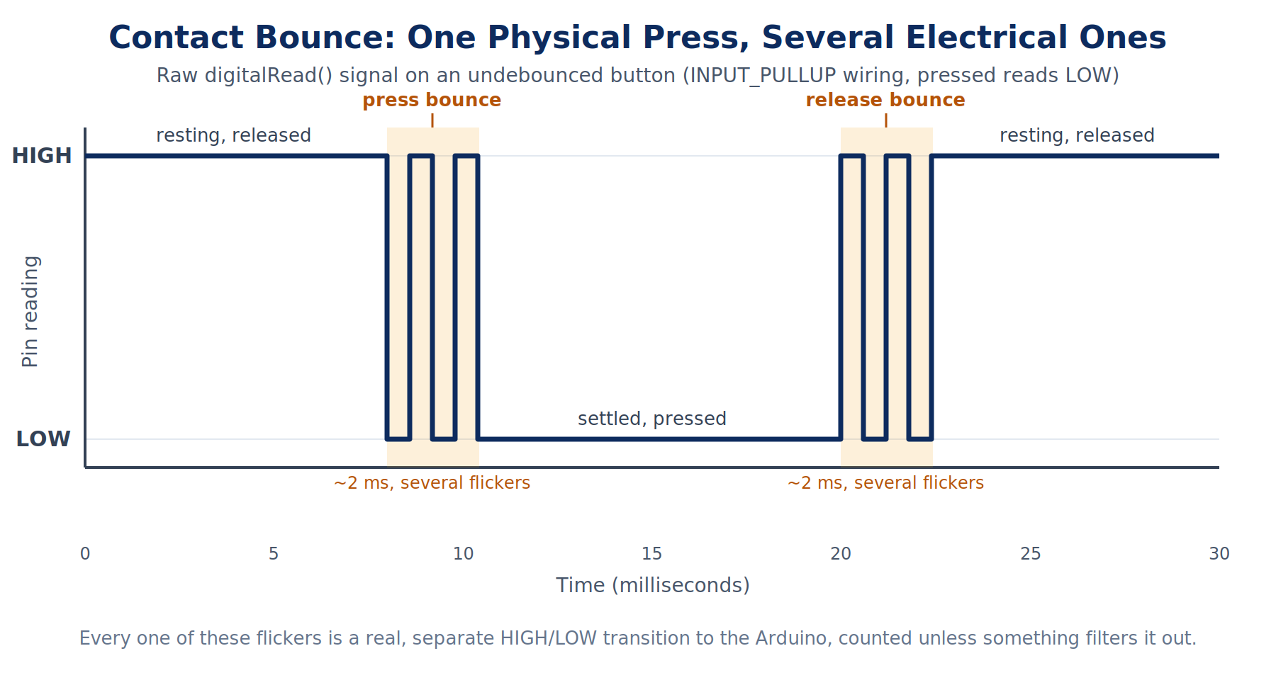
Picture an old wooden screen door on a spring, the kind that slams shut behind you on a summer afternoon. It doesn't gently come to rest against the frame. It slams, bounces open an inch, slams again a little softer, bounces again even less, and settles after two or three small hops that happen almost too fast to see. A mechanical pushbutton does the exact same thing, just at a scale you'll never see with your bare eyes. Inside that little plastic cap is a small metal dome or a pair of metal contacts. When you press the button, those contacts don't glide together and stop. They smack into each other, physically bounce apart by a microscopic distance, smack together again, and repeat that a handful of times before finally coming to rest, fully closed. The whole thing is over in a few milliseconds, way faster than your finger could ever feel it, but a microcontroller reading that pin hundreds of thousands of times a second sees every single one of those bounces as a separate, real electrical event: HIGH, LOW, HIGH, LOW, HIGH, LOW, then finally settling LOW and staying there. This physical settling behavior is called contact bounce, or just bounce, and it's not a manufacturing defect or a sign of a cheap button. Every mechanical switch does this, from a two-dollar tactile button to the power switch on a piece of professional audio gear. It's just what metal does when it meets metal fast.
Here's the part that makes this a software problem and not just a hardware curiosity: your Arduino's loop() runs so fast, usually tens of thousands of times per second for a simple sketch, that it can easily catch several of those individual bounces as separate press-and-release events. That's exactly why the naive if (digitalRead(pin) == LOW) count++; from the Lead miscounts. It isn't broken. It's doing precisely what you told it to do: count every time the pin reads LOW. The button is just handing it several LOW readings for what felt, to you, like one single, clean press.
What Does a Floating Pin Do?
Before pull-up and pull-down resistors make sense, you need to know what problem they're solving, and that means understanding what happens to a digital input pin with absolutely nothing connected to it. Imagine a light switch on a wall that isn't wired to anything at all, no wire to the light, no wire to the breaker box, just a switch mechanism sitting there in the wall doing nothing. Flip it up or down and nothing happens, obviously, because there's no circuit. Now imagine that switch is somehow still capable of reporting "on" or "off" to someone in another room, based on nothing but which way you happened to bump it last, or a stray breeze, or static electricity in the air. That's a genuinely unsettling thing for a switch to do, and it's almost exactly what a floating pin does on an Arduino.
A digital input pin (a pin you've told the Arduino to treat as an input with pinMode(pin, INPUT)) is, electrically, a very sensitive voltage detector. If nothing is actively holding that pin at a defined voltage, meaning it isn't firmly connected to either 5V (which reads as HIGH) or GND (which reads as LOW), the pin is said to be floating. A floating pin will pick up tiny stray electrical charges from nearby wires, from your own hand hovering near the breadboard, even from the AC wiring inside your walls, and report those stray charges back to digitalRead() as if they were real, meaningful signals. The value you get back from a floating pin isn't wrong, exactly, it's really reading something, but that something has nothing to do with whatever you were trying to sense. It can flicker between HIGH and LOW rapidly with no button anywhere near being pressed, purely from electrical noise. This is why this article is titled "Digital I/O You Can Trust": a floating pin is a digital input you fundamentally cannot trust, and a bouncing switch is a digital input you can only trust after you've dealt with the bounce. Both problems get fixed in this article, and it turns out the fix for the first one (giving a pin a defined resting state) is a prerequisite for reliably fixing the second.
A pushbutton, on its own, only closes a connection while you're pressing it. The rest of the time, unless something is actively pulling that pin to a known HIGH or LOW, the pin is floating exactly like the imaginary unwired light switch. That's the whole reason pull-up and pull-down resistors exist: to give a digital input pin a defined, trustworthy resting state, so the only thing that changes the reading is an actual button press, not stray electrical noise.
Pulling a Pin Down, the Hard Way
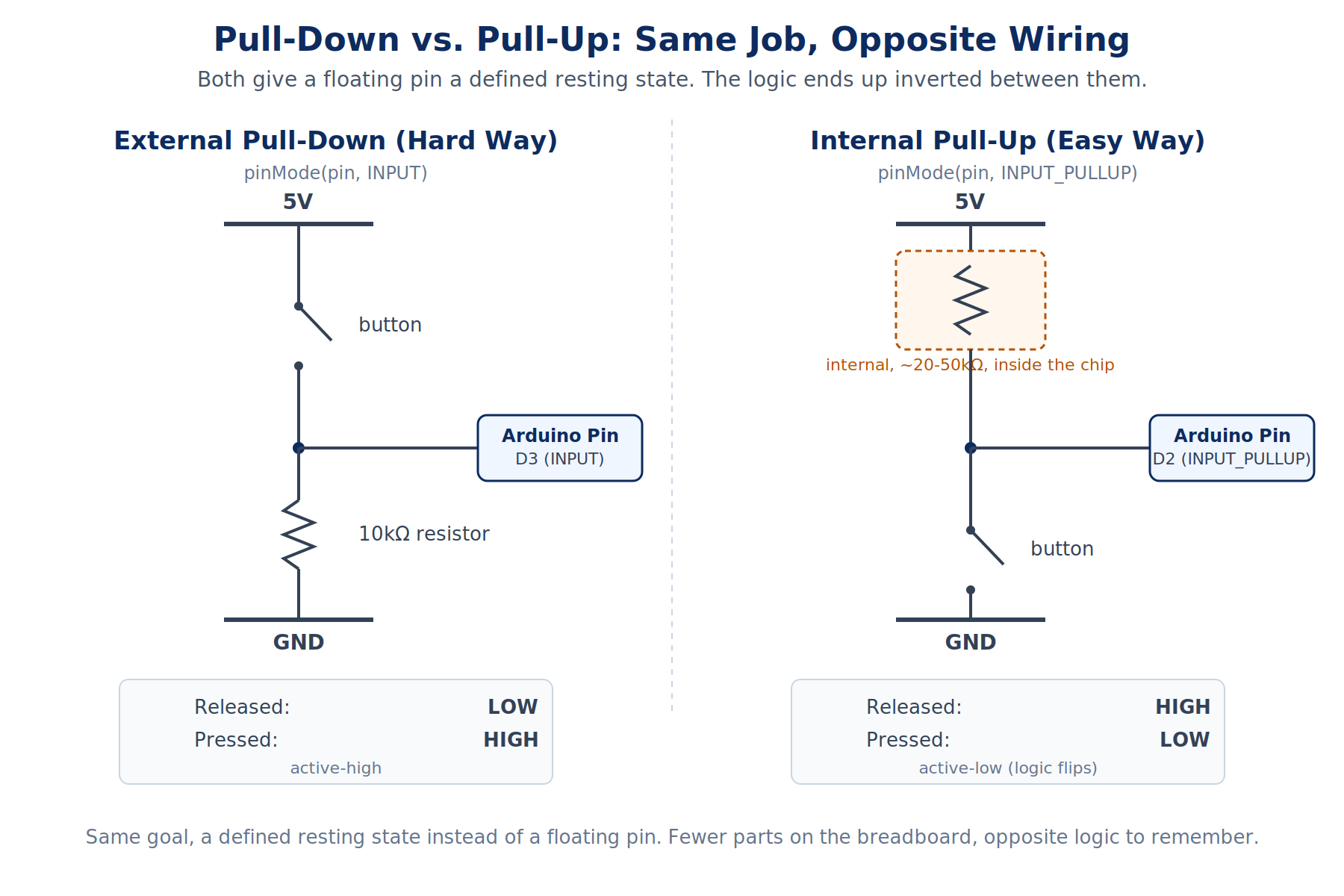
The most literal fix for a floating pin is to physically connect it to GND through a resistor, all the time, whether the button is pressed or not. This is called a pull-down resistor, because it "pulls" the pin's resting voltage down to a defined 0V (LOW) whenever the button isn't pressed. Here's the circuit, in words before you see it wired: one leg of the button connects to 5V. The other leg of the button connects to two things at once: the Arduino's input pin, and one leg of a 10kΩ resistor. The resistor's other leg connects to GND.
With that wiring, think through both states. Button not pressed: the only path from the input pin to anywhere is through that resistor down to GND, so the pin reads a firm, defined LOW. Button pressed: the button now directly connects the pin to 5V, and 5V overpowers the comparatively weak pull to GND through the resistor, so the pin reads a firm, defined HIGH. That resistor value matters more than it might look like it should. It needs to be large enough (10kΩ is a standard, safe choice) that when the button is pressed, only a tiny, harmless trickle of current flows from 5V straight to GND through it, instead of a real short circuit that could damage the pin or waste real power. This is why you'll see 10kΩ specifically, not 100Ω or 1MΩ, used as the default pull resistor value across the vast majority of Arduino tutorials and reference designs: it's the sweet spot between "strong enough to reliably hold the pin LOW against electrical noise" and "weak enough that pressing the button doesn't draw meaningful current."
With this wiring, pinMode(pin, INPUT) and a plain digitalRead(pin) give you exactly the logic you'd probably guess on your first try: pressed reads HIGH, released reads LOW. That's called active-high wiring, because the "active," meaningful state (button pressed) corresponds to the electrically higher voltage. It's intuitive, and it's also more parts, more wires, and one more thing that can go wrong on your breadboard (a loose resistor leg, a resistor in the wrong spot) compared to what's coming next.
Pulling a Pin Up the Easy Way, and Why the Logic Flips
Every Arduino chip has a small set of resistors already built into it, right next to each pin, that you can switch on entirely in software with zero extra wiring. That's what INPUT_PULLUP has been doing this whole series, since you first typed it in Part 4, without a plain-language explanation of what it meant until now. Instead of an external 10kΩ resistor wired to GND, pinMode(pin, INPUT_PULLUP) quietly connects an internal resistor (roughly 20kΩ to 50kΩ on an Uno, the exact value varies chip to chip and isn't something you need to worry about) between that pin and the Arduino's own internal 5V rail. That resistor "pulls" the pin's resting voltage up to a defined HIGH whenever nothing else is dragging it down, which is exactly where the name comes from.
With INPUT_PULLUP active, your button wiring gets dramatically simpler: one leg of the button to the input pin, the other leg straight to GND. No resistor on the breadboard at all, because the resistor is already inside the chip. That's the entire case for why INPUT_PULLUP gets used so often: it's the easy way, the same relationship Part 5 described between managing your own char buffer and letting String do the bookkeeping for you. Fewer parts on the breadboard means fewer things that can be wired wrong, and that's worth a lot when you're troubleshooting a circuit that isn't behaving.
But here's the gotcha, and it's worth knowing before it costs you a confusing debugging session: the logic flips. Since the internal resistor is pulling the pin up toward 5V, an unpressed button reads HIGH, not LOW. Pressing the button connects the pin straight to GND, overpowering that weak internal pull-up, so a pressed button reads LOW. That's the opposite of the pull-down wiring from the last section, and it's called active-low: the "active," meaningful state (button pressed) corresponds to the electrically lower voltage, which is backwards from what most people guess on their first try. This is why you've seen lines like if (digitalRead(BTN_PIN) == LOW) in Part 4 and Part 5's projects with only a one-line comment explaining it (// INPUT_PULLUP: pressed reads LOW). Now you know the electrical reason that comment was there, instead of just trusting it.
| Wiring | pinMode() | Extra parts on breadboard | Unpressed reads | Pressed reads |
|---|---|---|---|---|
| External pull-down (hard way) | INPUT | 1 resistor, 3 extra wires | LOW | HIGH |
| Internal pull-up (easy way) | INPUT_PULLUP | None | HIGH | LOW |
Neither wiring is "more correct" than the other. Active-high pull-down wiring is the right call when you're already running a resistor to that pin for another reason, or when you're working with a chip or module that doesn't have internal pull-ups available at all. But for a plain Arduino pushbutton like the ones in this kit, INPUT_PULLUP is almost always the better default, which is why the rest of this series has quietly been using it since Part 4. From here on, this article's own code normalizes both wirings into one consistent "is this button physically pressed right now" boolean before anything else touches it, so the rest of your program never has to remember which wiring style is underneath a given button. You'll see exactly how in the practical project.
Debounce, the Real Fix
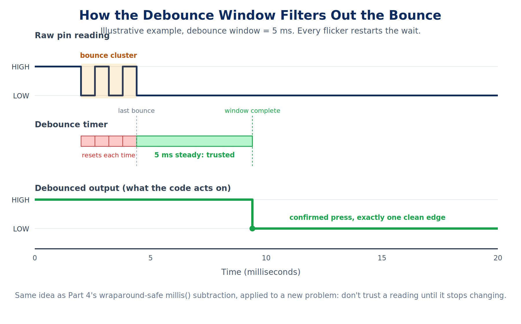
Pull resistors solve the floating-pin problem: they guarantee your button has a defined resting state. They do nothing at all about bounce: a properly pulled-up or pulled-down button still chatters through several rapid HIGH/LOW flickers during the brief window when its contacts are physically settling. Fixing that for real is what this whole article has been building toward, and it comes down to one idea: don't trust a reading until it's held steady for a short window of time.
The pattern works like this, in plain language before you see the code. Every time loop() runs, read the pin. If that raw reading is different from the last raw reading you saw, something changed, maybe a real press, maybe just another bounce, so note the time and start watching. If enough time has passed since that last change (a debounce window, typically somewhere between 10 and 50 milliseconds for a standard tactile button) without the reading changing again, you can finally trust it: whatever the pin is reading right now is the button's real, settled state, not a mid-bounce flicker. Only then do you treat it as a genuine press or release.
This is exactly the wraparound-safe millis() subtraction pattern from Part 4 (now - lastChangeTime >= WINDOW_MS), applied to a new problem. No delay() anywhere, same standing rule since Part 4: a delay()-based debounce would freeze your entire sketch for the length of the debounce window every single time the button so much as flickers, which defeats the whole point of a non-blocking sketch that can also handle an LED chase, a potentiometer, and a Serial console at the same time, the way Part 5's project did.
// A minimal, real debounce on one button, INPUT_PULLUP wiring (pressed reads LOW).
const uint8_t BTN_PIN = 2;
const unsigned long DEBOUNCE_MS = 25;  // longer than typical bounce (a few ms) but short enough to feel instant

bool lastRawState = HIGH;  // unfiltered, so it can flicker while the contacts bounce
bool debouncedState = HIGH;  // the value the rest of the sketch is allowed to trust
unsigned long lastChangeTime = 0;  // restarts whenever the raw reading flickers

void setup() {
  pinMode(BTN_PIN, INPUT_PULLUP);
  Serial.begin(115200);
}

void loop() {
  unsigned long now = millis();
  bool raw = digitalRead(BTN_PIN);

  if (raw != lastRawState) {  // can't tell a press from a bounce yet, so restart the timer
    lastChangeTime = now;
    lastRawState = raw;
  }

  if ((now - lastChangeTime) >= DEBOUNCE_MS && debouncedState != lastRawState) {
    // the raw reading has held perfectly still for the whole window: trust it now
    debouncedState = lastRawState;
    if (debouncedState == LOW) {  // act on the press only, not the release
      Serial.println(F("confirmed press"));
    }
  }
}
Notice what that if (raw != lastRawState) line is really doing: it resets the settling-window timer on every single flicker, not just the first one. That's the detail that makes this a real fix and not just a fixed delay after the first edge. A cheap or worn-out button that bounces for longer than expected simply keeps resetting the timer until it settles, so the debounce window always measures from the last flicker, whenever that happens to be, not a guess made the instant the first bounce was seen.
Exercises
Work through these in order. Each one proves a single rule. By the last one, you're one small step from the practical project.
Bill of Materials
Everything used across this article's exercises and its practical project. If you kept Part 4 and 5's LEDs wired up, you already have three of the four in the bar-graph array, and one pushbutton from earlier parts. This time you need a second pushbutton and one new part: a plain fixed 10kΩ resistor, not to be confused with the 10kΩ potentiometer already in your kit (that's a different, 3-pin part).
| Component | Description | Buy on Amazon | Buy on Temu | Buy on SparkFun | Buy on Seeed Studio |
|---|---|---|---|---|---|
| Arduino Uno | Standard microcontroller board | Amazon Link | Temu Link | SparkFun Link | Seeed Link |
| Breadboard & Jumper Wires | For prototyping connections | Amazon Link | Temu Link | SparkFun Link | Seeed Link |
| 5mm LED (×4) | Four standard through-hole LEDs for the bar-graph counter display | Amazon Link | Temu Link | SparkFun Link | Not yet available |
| 220Ω resistor (×4) | One current-limiting resistor per LED | Amazon Link | Temu Link | SparkFun Link | Seeed Link |
| Momentary tactile pushbutton (×2) | Two normally-open switches: one for the hard-way pull-down demo, one for the easy-way pull-up demo. If you kept a button from Part 4 or 5 wired up, you already have one of these two. | Amazon Link | Temu Link | SparkFun Link | Not yet available |
| 10kΩ fixed resistor (×1) | The actual pull-down resistor for Exercise 2's hard-way wiring. A plain 2-leg resistor, not the potentiometer below. | Amazon Link | Temu Link | SparkFun Link | Seeed Link |
| 10kΩ potentiometer | Analog input that tunes the debounce window in real time | Amazon Link | Temu Link | SparkFun Link | Not yet available |
The products linked above may contain affiliate links. The Makers Workbench earns from qualifying purchases when these links are used.
No hardware on hand? You can still build this one. Jump to the Lab embed in the practical project section below and run this whole build right in your browser.
Exercise 1: Feel the Chatter
- You will: Wire up one plain pushbutton and watch, with your own eyes on the Serial Monitor, how many raw transitions a single physical press-and-release produces.
- Parts: One Arduino Uno, breadboard, one momentary tactile pushbutton. No resistor needed yet,
INPUT_PULLUPhandles that. - Wiring: One leg of the button to D2, the other leg straight to GND.
- Sketch:
const uint8_t BTN_PIN = 2;  // other leg to GND; the internal pull-up replaces an external resistor

bool lastState = HIGH;  // INPUT_PULLUP rests HIGH, so start there

void setup() {
  pinMode(BTN_PIN, INPUT_PULLUP);
  Serial.begin(115200);
  Serial.println(F("Press and release the button once, slowly and normally."));
}

void loop() {
  bool reading = digitalRead(BTN_PIN);  // raw on purpose: every bounce shows up here
  if (reading != lastState) {
    lastState = reading;
    Serial.print(F("t="));
    Serial.print(millis());  // timestamps show how close together the flickers land
    Serial.println(reading == LOW ? F("  -> LOW (pressed)") : F("  -> HIGH (released)"));
  }
}
- What to notice: One deliberate, normal press-and-release should print a HIGH-to-LOW line, then a LOW-to-HIGH line, at minimum. On most tactile buttons you'll see several extra lines clustered within a couple of milliseconds of each other, right around the press and right around the release, that's the bounce. Watch the
t=timestamps: the extra transitions are packed impossibly close together for a human finger to have caused them on purpose. - If it fails: You only ever see exactly one HIGH-to-LOW and one LOW-to-HIGH line, no matter how many times you press: that's not a bug in the sketch, some buttons simply bounce for less than one
loop()pass can catch. Try pressing faster or more off-center on the button cap, or don't worry about it, either way you've confirmedINPUT_PULLUP's inverted logic works as expected, which is what the rest of this article builds on.
Exercise 2: Wire a Pull-Down the Hard Way
- You will: Build the external pull-down circuit from "Pulling a Pin Down, the Hard Way" with your own hands, and confirm its logic reads the opposite way from Exercise 1's
INPUT_PULLUPwiring. - Parts: A second momentary tactile pushbutton, the new 10kΩ fixed resistor.
- Wiring:
| Part | Connects to |
|---|---|
| Button leg 1 | 5V |
| Button leg 2 | D3, and also to one leg of the 10kΩ resistor |
| 10kΩ resistor, other leg | GND |
- Sketch:
const uint8_t BTN_PIN = 3;  // the second button, wired with an external pull-down resistor this time

void setup() {
  pinMode(BTN_PIN, INPUT);  // plain INPUT, not INPUT_PULLUP: the external resistor is doing that job now
  Serial.begin(115200);
  Serial.println(F("Press and release the pull-down button."));
}

void loop() {
  static bool lastState = LOW;         // unpressed reads LOW with a pull-down; starts here on purpose
  bool reading = digitalRead(BTN_PIN);
  if (reading != lastState) {
    lastState = reading;
    Serial.println(reading == HIGH ? F("pressed (HIGH)") : F("released (LOW)"));
  }
}
- What to notice: This button reports pressed as HIGH and released as LOW, the exact opposite of Exercise 1's
INPUT_PULLUPbutton on D2. Both are correct. They're just two different, equally valid ways of giving a floating pin a defined resting state. - If it fails: The pin reads erratically even when you're not touching the button (rapid, meaningless flickering with no pattern): double-check the resistor is bridging D3's node to GND, not floating on the breadboard with one leg in an empty row. A pull-down resistor that isn't connected to GND doesn't pull down anything.
Exercise 3: Switch to the Built-in Pull-Up (the Easy Way)
- You will: Rewire the exact same D3 button from Exercise 2 to use
INPUT_PULLUPinstead, removing the external resistor entirely, and see firsthand how much simpler the wiring gets. - Parts: Same button from Exercise 2. Remove the 10kΩ resistor and its two wires.
- Wiring: One leg of the button to D3, the other leg straight to GND. That's it, two wires instead of the four-connection pull-down circuit from Exercise 2.
- Sketch: identical to Exercise 2's, with two changes:
const uint8_t BTN_PIN = 3;

void setup() {
  pinMode(BTN_PIN, INPUT_PULLUP);  // changed from INPUT: no external resistor needed anymore
  Serial.begin(115200);
  Serial.println(F("Press and release the button again, now on INPUT_PULLUP."));
}

void loop() {
  static bool lastState = HIGH;  // changed from LOW: INPUT_PULLUP rests HIGH, not LOW
  bool reading = digitalRead(BTN_PIN);
  if (reading != lastState) {
    lastState = reading;
    Serial.println(reading == LOW ? F("pressed (LOW)") : F("released (HIGH)"));
  }
}
- What to notice: Same physical button, same pin, same behavior from your point of view as the person pressing it, but the logic is now inverted (pressed reads LOW) and the resistor is gone from the breadboard entirely. This is the whole tradeoff from the "Pulling a Pin Up" section, now in your own hands instead of just on the page.
- If it fails: The Serial Monitor shows
pressed (LOW)printing on its own with nothing touching the button: check that the resistor and its wires were removed, a leftover pull-down resistor still wired in parallel with anINPUT_PULLUPpin will fight the internal pull-up and can cause exactly this kind of ghost reading.
Exercise 4: Debounce It for Real
- You will: Apply the real
millis()-timestamp debounce pattern to the D2 button from Exercise 1, replacing a raw, un-debounced press counter with one that only counts genuine, settled presses. - Parts: Same D2 button from Exercise 1. D3's button and resistor from Exercise 2/3 aren't used in this one.
- Wiring: Same as Exercise 1.
- Sketch:
const uint8_t BTN_PIN = 2;
const unsigned long DEBOUNCE_MS = 25;  // settling window: adjust and re-test to feel what changes

bool lastRawState = HIGH;
bool debouncedState = HIGH;
unsigned long lastChangeTime = 0;
uint16_t rawCount = 0;            // counts every raw LOW reading, bounce included, for comparison
uint16_t debouncedCount = 0;      // counts only confirmed, settled presses

void setup() {
  pinMode(BTN_PIN, INPUT_PULLUP);
  Serial.begin(115200);
}

void loop() {
  unsigned long now = millis();
  bool raw = digitalRead(BTN_PIN);

  if (raw != lastRawState) {   // any change at all resets the settling-window timer
    lastChangeTime = now;
    lastRawState = raw;
    if (raw == LOW) {
      rawCount++;               // naive count: every single flicker toward LOW counts, bounce included
    }
  }

  if ((now - lastChangeTime) >= DEBOUNCE_MS && debouncedState != lastRawState) {
    debouncedState = lastRawState;   // the reading has held steady long enough to trust
    if (debouncedState == LOW) {
      debouncedCount++;              // real count: only a settled, confirmed press adds one
      Serial.print(F("raw count: "));
      Serial.print(rawCount);
      Serial.print(F("   debounced count: "));
      Serial.println(debouncedCount);
    }
  }
}
- What to notice: Press the button five separate times, deliberately, with a clear pause between each press.
debouncedCountshould read exactly 5.rawCountwill very likely read higher, sometimes noticeably higher, proving the naive approach from the Lead really was overcounting, and that the debounce logic above genuinely fixes it rather than just hiding the problem. - If it fails:
debouncedCountstill overcounts: check thatlastChangeTimeis being reset on every raw change (inside theif (raw != lastRawState)block), not just once. If it only resets on the very first flicker, a button that bounces longer thanDEBOUNCE_MSwill still slip a second count through before it finishes settling.
You're one small step from the full project: two buttons, wired two different ways, both debounced for real, driving an LED bar graph, with a potentiometer letting you dial the debounce window itself up and down.
Practical Project: Reliable Two-Button Counter with a Tunable Debounce Window
Done looks like: turn the potentiometer all the way to its shortest debounce setting and mash the increment button as fast as you comfortably can. The bar graph should visibly misbehave, jumping by more than one LED per press some of the time, because the debounce window is too short to fully absorb the bounce. Now slowly turn the potentiometer up. At some point the misbehavior stops entirely: one press, one LED, every time, no matter how you mash it. Keep turning past that point and you'll start to feel the counter lag noticeably behind your actual button presses, that's the cost of an overly long debounce window. A stranger with no explanation from you should be able to press the buttons, watch the bar graph, and find that same "just right" zone on the dial themselves.
What you will build
- Two buttons, wired two different ways, normalized into one consistent "is this physically pressed right now" reading before anything else in the sketch touches it: an increment button on D2 using
INPUT_PULLUP(the easy way), and a decrement button on D3 using an external 10kΩ pull-down resistor (the hard way). - Real
millis()-timestamp debounce logic (from Exercise 4) applied to both buttons, driven by parallel arrays instead of separate variables for each one, the same pattern Part 5 taught for the LED chase. - A 4-LED bar-graph display (D6-D9, the same layout as Part 5's array) that fills up one LED per confirmed increment and empties one LED per confirmed decrement, clamped at 0 and 4.
- A potentiometer on A0 that scales the debounce window itself, from a too-short 5ms up to a too-long 150ms, live, with the current value printed to Serial whenever it changes meaningfully.
Components needed
Everything is in the Bill of Materials above: Arduino Uno, breadboard and jumper wires, four 5mm LEDs with four 220Ω resistors, two tactile pushbuttons, one fixed 10kΩ resistor, and one 10kΩ potentiometer.
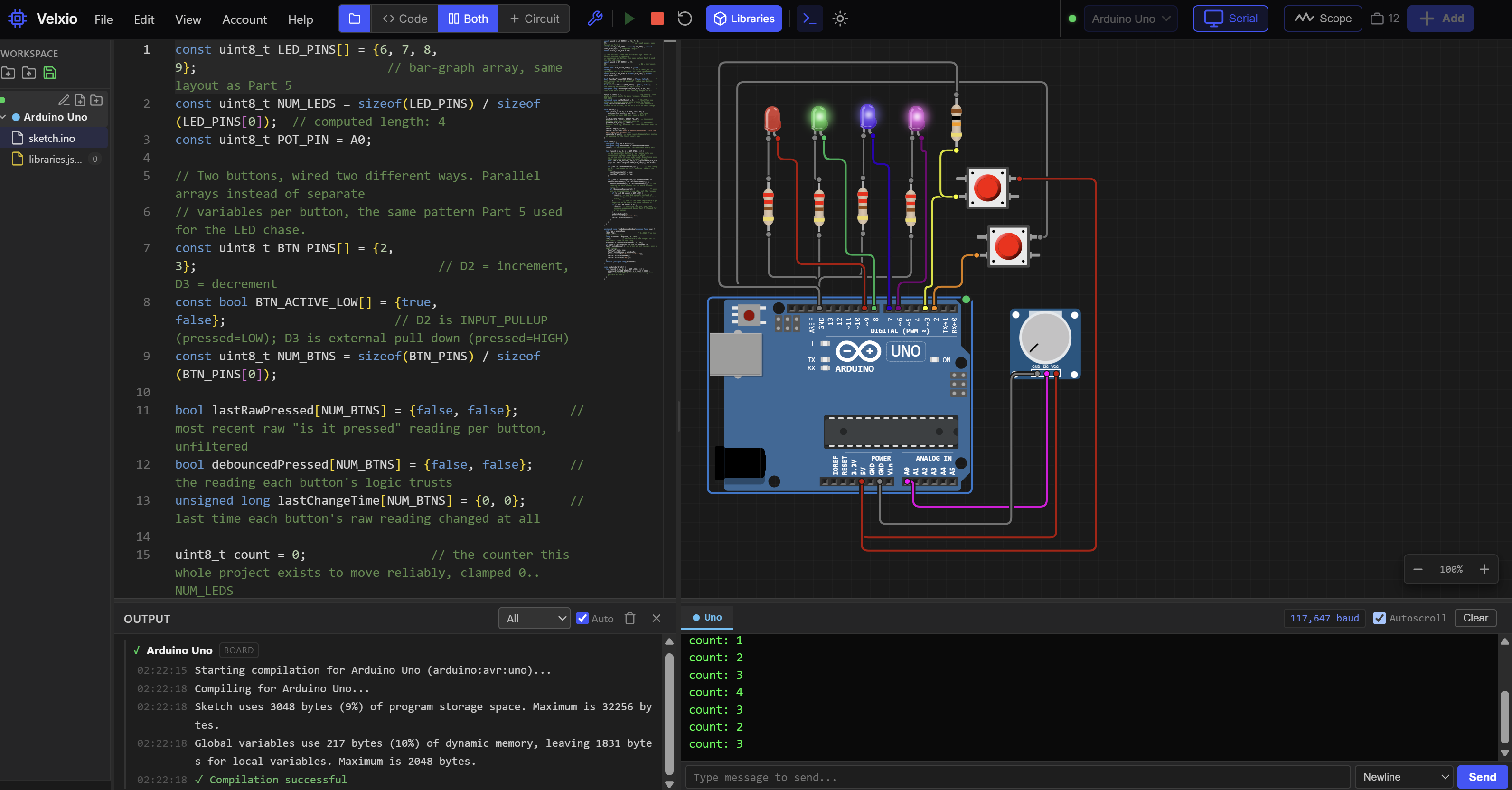
Lab embed
Wiring
| Part | Arduino |
|---|---|
| LED 1 anode, through 220Ω resistor | D6 |
| LED 2 anode, through 220Ω resistor | D7 |
| LED 3 anode, through 220Ω resistor | D8 |
| LED 4 anode, through 220Ω resistor | D9 |
| All four LED cathodes | GND |
| Increment button, leg 1 | D2 |
| Increment button, leg 2 | GND |
| Decrement button, leg 1 | 5V |
| Decrement button, leg 2 | D3, and one leg of the 10kΩ fixed resistor |
| 10kΩ fixed resistor, other leg | GND |
| Potentiometer wiper (center pin) | A0 |
| Potentiometer outer pins | 5V and GND |
No new libraries. Every function here is core Arduino, the same set Parts 3 and 4 already covered.
The sketch
const uint8_t LED_PINS[] = {6, 7, 8, 9};                          // bar-graph array, same layout as Part 5
const uint8_t NUM_LEDS = sizeof(LED_PINS) / sizeof(LED_PINS[0]);
const uint8_t POT_PIN = A0;

// Two buttons, wired two different ways. Parallel arrays instead of separate
// variables per button, the same pattern Part 5 used for the LED chase.
const uint8_t BTN_PINS[] = {2, 3};                                 // D2 = increment, D3 = decrement
const bool BTN_ACTIVE_LOW[] = {true, false};                       // D2 is INPUT_PULLUP (pressed=LOW); D3 is external pull-down (pressed=HIGH)
const uint8_t NUM_BTNS = sizeof(BTN_PINS) / sizeof(BTN_PINS[0]);

bool lastRawPressed[NUM_BTNS] = {false, false};  // unfiltered, so it can flicker while a button bounces
bool debouncedPressed[NUM_BTNS] = {false, false};
unsigned long lastChangeTime[NUM_BTNS] = {0, 0};

uint8_t count = 0;  // clamped to 0..NUM_LEDS so the bar graph never over- or underflows
unsigned long lastPotPrint = 0;
long lastPrintedWindow = -1;  // -1 never matches a real window, so the first value always prints

void setup() {
  for (uint8_t i = 0; i < NUM_LEDS; i++) {
    pinMode(LED_PINS[i], OUTPUT);
  }
  pinMode(BTN_PINS[0], INPUT_PULLUP);  // increment button: easy way, internal pull-up
  pinMode(BTN_PINS[1], INPUT);         // decrement button: hard way, external pull-down resistor does the work
  Serial.begin(115200);
  Serial.println(F("Part 6 debounced counter. Turn the pot, mash the buttons."));
  updateBarGraph();  // draw count=0 immediately instead of waiting for the first loop() pass
}

void loop() {
  unsigned long now = millis();
  unsigned long debounceMs = readDebounceWindow(now);  // re-read every pass so turning the pot takes effect live

  for (uint8_t i = 0; i < NUM_BTNS; i++) {
    // Normalize this button's raw reading into one consistent boolean, regardless of which
    // wiring style it uses underneath. Everything below this line only ever sees "pressed" or not.
    bool raw = BTN_ACTIVE_LOW[i] ? (digitalRead(BTN_PINS[i]) == LOW) : (digitalRead(BTN_PINS[i]) == HIGH);

    if (raw != lastRawPressed[i]) {        // any change at all, real press or still bouncing, resets the timer
      lastChangeTime[i] = now;
      lastRawPressed[i] = raw;
    }

    if ((now - lastChangeTime[i]) >= debounceMs && debouncedPressed[i] != lastRawPressed[i]) {
      debouncedPressed[i] = lastRawPressed[i];  // the reading has held steady for the whole window: trust it
      if (debouncedPressed[i]) {                // only act on the confirmed press edge, not the release
        if (i == 0 && count < NUM_LEDS) {  // check the bound first: count is unsigned, so 0 - 1 would wrap to 255
          count++;
        }
        if (i == 1 && count > 0) {
          count--;
        }
        updateBarGraph();
        Serial.print(F("count: "));
        Serial.println(count);
      }
    }
  }
}

unsigned long readDebounceWindow(unsigned long now) {
  int raw = analogRead(POT_PIN);
  long windowMs = map(raw, 0, 1023, 5, 150);            // deliberately wide range: 5ms is too short, 150ms is too long
  windowMs = constrain(windowMs, 5, 150);
  if (now - lastPotPrint >= 250 && windowMs != lastPrintedWindow) {  // print at most 4x/sec, only on real change
    lastPotPrint = now;
    lastPrintedWindow = windowMs;
    Serial.print(F("debounce window: "));
    Serial.print(windowMs);
    Serial.println(F("ms"));
  }
  return (unsigned long)windowMs;
}

void updateBarGraph() {
  for (uint8_t i = 0; i < NUM_LEDS; i++) {
    digitalWrite(LED_PINS[i], i < count ? HIGH : LOW);
  }
}
Every pin const above matches the Wiring table row for that signal: LED_PINS[] is 6, 7, 8, 9. BTN_PINS[] is 2 (increment) then 3 (decrement). POT_PIN is A0. Checked signal by signal, both directions.
What's happening
loop() reads the potentiometer first, then walks both buttons in a single for loop using the parallel arrays declared at the top, the same array-of-related-values pattern Part 5 taught for the LED chase, just applied to buttons instead of LEDs this time. The line that does the real work is the normalization at the top of that loop: bool raw = BTN_ACTIVE_LOW[i] ? (digitalRead(...) == LOW) : (digitalRead(...) == HIGH);. That one line is the entire payoff of understanding pull-up versus pull-down from earlier in this article. Once it runs, everything after it, the debounce timing, the increment/decrement logic, the bar graph, never has to know or care which physical wiring style a given button used. Both buttons speak the same "pressed" boolean by the time the debounce logic sees them.
The debounce block itself is Exercise 4's pattern, unchanged in spirit, just running once per button inside the loop instead of being written out twice by hand. readDebounceWindow() is new this project: it reads the potentiometer, maps it to a debounce window between 5 and 150 milliseconds, and only prints to Serial when that value changes and at most four times a second, so turning the knob doesn't flood your Serial Monitor with a new line on every single loop() pass.
The one line worth slowing down on is the guarded increment and decrement: if (i == 0 && count < NUM_LEDS) { count++; } and if (i == 1 && count > 0) { count--; }. count is a uint8_t, the same "smallest type that can honestly hold the value" habit Part 5 taught, and a uint8_t can never legitimately hold a negative number. Decrementing count past zero wouldn't throw an error or stop at zero on its own, it would silently wrap around to 255, and the bar graph's i < count check would then treat every LED as "on" because 255 is bigger than any realistic index. Checking the bound explicitly before changing count, instead of changing it first and trying to clean up afterward, avoids that trap entirely. This is the exact same unsigned-wraparound danger Part 5 flagged when it warned you never to hand-type an array's length: trusting unsigned math instead of guarding it is where those bugs come from.
If the project fails the "done" test
The bar graph never changes at all: check that both pinMode() calls in setup() match the Wiring table (INPUT_PULLUP for D2, plain INPUT for D3), a swapped pair will leave one button always reading as "pressed" and the other never. One button seems to work but the other doesn't respond: confirm the BTN_ACTIVE_LOW[] array entry for that button matches its actual wiring, true for the INPUT_PULLUP button, false for the external pull-down button, a mismatched entry inverts that button's logic and makes it look permanently stuck. The counter still occasionally jumps by more than one even with the potentiometer turned most of the way up: you may simply have a worn-out or low-quality button that bounces longer than 150ms, which is unusual but not impossible, try the other button in that same spot to isolate whether it's the button or the wiring.
Troubleshooting
| Symptom | Cause | Fix |
|---|---|---|
| Counter increases by more than one per press, even at a long debounce window | Bounce lasting longer than the current DEBOUNCE_MS/potentiometer setting | Turn the potentiometer toward its longer end, or raise the fixed DEBOUNCE_MS in the exercises' code |
| Counter feels laggy, noticeably slower to respond than your actual press | Debounce window set too long for the potentiometer's current position | Turn the potentiometer toward its shorter end until responsiveness returns, without letting double-counting come back |
D2 button (INPUT_PULLUP) always reads as pressed, even untouched | Missing GND connection on that button's second leg, leaving the pin floating instead of pulled HIGH | Confirm the button's second leg lands in the same breadboard row as a real GND connection |
| D3 button (external pull-down) reads erratically with no pattern, even untouched | The 10kΩ resistor isn't bridging the pin's node to GND, so the pin is still floating | Check both resistor legs land in the correct rows: one in the same row as the button leg and D3's jumper, one in a GND rail |
| D3 button never registers a press at all | Button's 5V leg isn't connected to 5V, so pressing it does nothing to the pin's voltage | Confirm the button leg wired to 5V is in a row connected to the breadboard's 5V rail, not a floating row |
| Bar graph fills past all 4 LEDs or seems to wrap around | count allowed to go outside 0..NUM_LEDS, usually from skipping the guarded if checks around count++/count-- | Confirm both increment and decrement are guarded with count < NUM_LEDS / count > 0, never adjusted unconditionally |
| Both buttons seem to do the same thing (both increment, or both decrement) | The i == 0 / i == 1 check inside the debounce block doesn't match BTN_PINS[]'s actual order | Confirm BTN_PINS[] is {2, 3} in that order, matching the Wiring table, and that the increment logic checks i == 0 |
| Serial Monitor floods with a new debounce-window line on almost every pass | The 250ms print-throttle check in readDebounceWindow() was removed or altered | Confirm the now - lastPotPrint >= 250 guard is still in place before the Serial.print calls |
Where This Fits in the Series
You can now explain, and defend with a working circuit, why a mechanical switch needs help to report a clean reading at all, wire that help two different ways depending on what a project calls for, and write a debounce routine that fixes chatter for real instead of just hoping it doesn't show up. Every button this series touches from here forward, in every catalog project and every later part, can lean on this pattern instead of the plain edge-detect Parts 4 and 5 explicitly flagged as a placeholder.
- Part 4: Timing Without delay(), millis(), micros(), and Non-Blocking Loops, whose control panel project first deferred real debounce to this part
- Part 5: Arrays, Strings, and Data in C++, whose LED array project made the same deferral and whose parallel-array pattern this part's two-button loop reuses directly
Two catalog pieces are anchored to this part but aren't written yet, and aren't part of this article: a PIR HC-SR501 motion-sensor housing model, and a planned combination-lock project that will lean on real debounce once it exists. Both are planned, not yet published.
Wrap-Up and What's Next
A mechanical switch bounces because metal contacts physically settle over a few milliseconds, not because anything is broken, and a floating digital pin can't be trusted until something actively holds it at a defined HIGH or LOW. An external pull-down resistor and Arduino's built-in INPUT_PULLUP both solve that floating-pin problem, just with opposite resting logic and a different amount of wiring. Real debounce means resetting a settling-window timer on every raw change and only trusting a reading once it's held steady through that whole window, using millis(), never delay(), so the rest of your sketch keeps running while it waits.
Next up, Part 7: Systematic Debugging: A Method, Not a Miracle, where the ad hoc troubleshooting habits this series has been building since Part 3 get organized into an actual repeatable method.
Want to go deeper? Download the full eBook once the series is complete, and subscribe for the rest of the Arduino Mastery Series.
Hack The World and Make Awesome.