
Part 8 taught the Arduino to notice one brief event even while loop() was busy. Part 9 gives it two related event streams and asks a harder question: did the shaft move, and which direction did it move? Those two streams come from a rotary encoder. Read together, they turn a spinning knob into signed position data.
A single pulse line can tell you that something moved, but it cannot reliably tell you which way. A rotary encoder solves that problem with two digital channels that change in a staggered order. The order is the information. If channel A changes before channel B, the shaft moved one way. If B changes before A, it moved the other way. The electrical idea is simple, but contact bounce, inconsistent encoder terminology, and several different decoding methods make the first project more confusing than it needs to be.
We will stay with the Arduino Uno and classic Nano. D2 and D3 are reserved for encoder channels A and B because those boards expose only two ordinary external-interrupt pins. The encoder’s button uses D4 and is polled and debounced in Part 6 style. By the end, you will build an Interrupt-Driven Position and Direction Dial that reports raw transitions, normalized detents, direction, and rejected two-bit jumps without printing or doing presentation work inside an interrupt service routine.
What Does an Incremental Rotary Encoder Report?
A potentiometer behaves like a stop-to-stop position control. Turn it to the middle and its output voltage sits near the middle of its range. Power the project off and back on, and the voltage still represents the knob’s physical angle. An incremental rotary encoder reports something different. It reports changes in position as the shaft turns. It does not remember an absolute zero point by itself.
That difference is why an encoder can spin continuously. The Arduino starts with a software position such as zero, then adds or subtracts as transitions arrive. If you need “zero” to correspond to a real mechanical location after power-up, another sensor, a limit switch, or saved calibration must establish that reference. This chapter’s button resets the software position, so zero means “where the shaft was when I pressed reset.”
The two encoder outputs are commonly labeled A and B. Modules often call the same signals CLK and DT. CLK and DT are convenient board labels, but they do not change the underlying job: there are two square-like digital signals separated in phase. On a bare encoder the shared contact is labeled C, and on a module it is the GND pin.
How Do Two Channels Show Direction?
Picture two people walking through a narrow doorway, one half a step ahead of the other. A camera that only sees one person can tell that somebody passed. A camera that sees both can also tell who led. The encoder’s two contacts work the same way. Their electrical patterns are offset by one quarter of a cycle, which is a 90-degree phase difference. That arrangement is called quadrature.
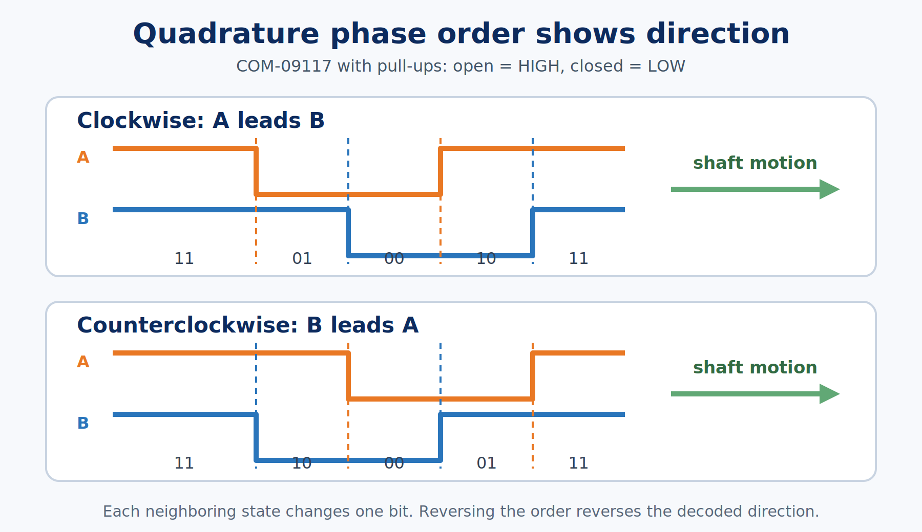
With the encoder wired as this article specifies, its internal pull-ups make open contacts read HIGH and closed contacts read LOW. At a stable detent, both channels normally read HIGH. During a slow clockwise step, A leads B and the states follow 11 → 01 → 00 → 10 → 11. Counterclockwise movement visits the same states in reverse: 11 → 10 → 00 → 01 → 11.
The words clockwise and counterclockwise depend on which terminal you call A, which side of the encoder you are viewing, and how the part is mounted. Swapping A and B reverses the sign without damaging anything. The important fact is not that one universal waveform must always mean clockwise. The important fact is that one phase order means one direction and the reverse order means the other.
What Is the Legal Gray-Code Sequence?
The two channel bits can form four states: 00, 01, 10, and 11. A well-behaved encoder moves between neighboring states by changing only one bit at a time. That one-bit-at-a-time pattern is Gray code. It prevents an ideal decoder from having to decide which of two bits changed first during a legal step.
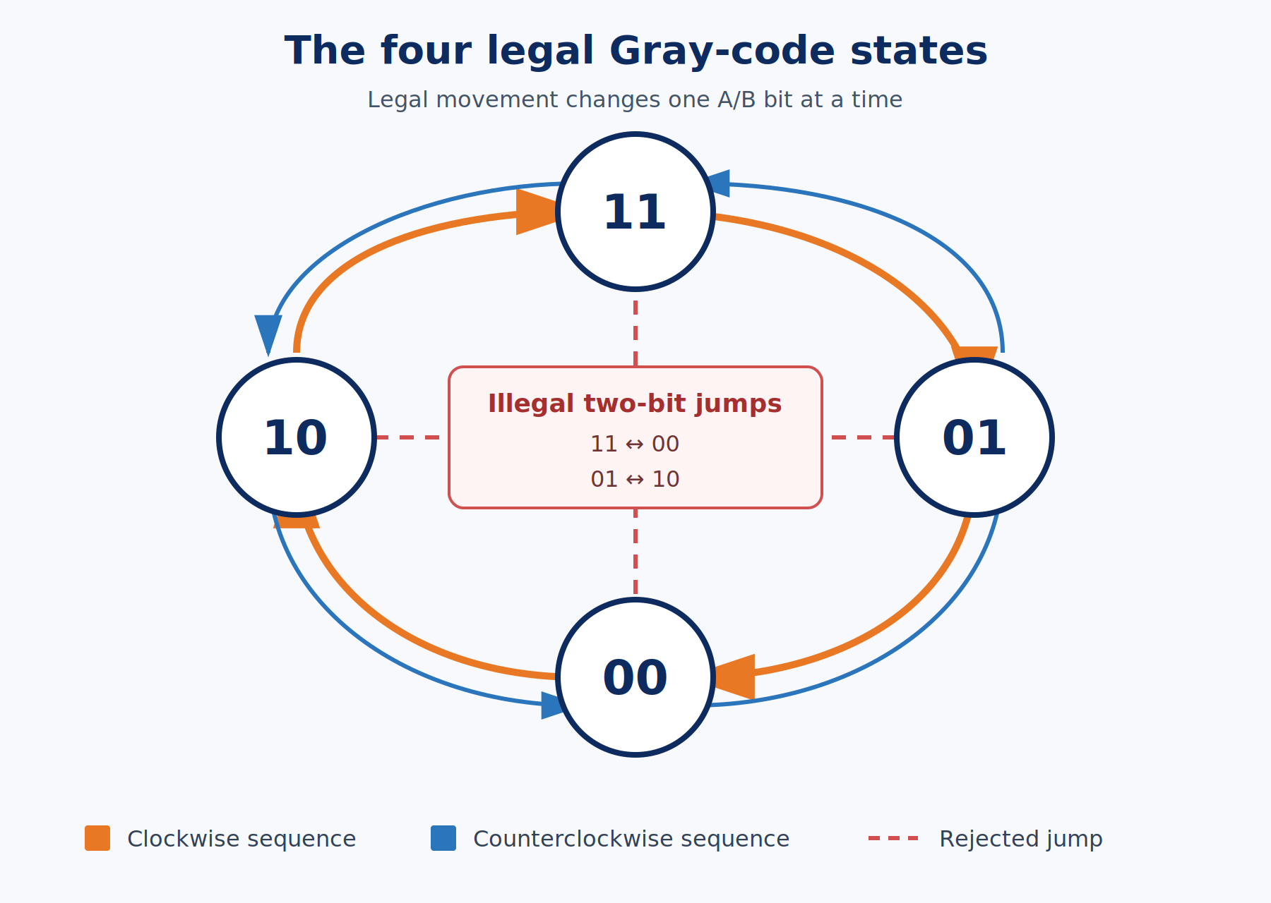
Starting at 11, the next legal state is either 01 or 10. A direct jump from 11 to 00 changes both bits at once. The same is true for 01 to 10. Those two-bit jumps are illegal in the ideal sequence. They usually mean the sketch missed an intermediate edge, sampled during noisy contact motion, or has a wiring problem.
Rejecting illegal jumps is useful, but it is not a magic debounce filter. Contact bounce on one channel can produce legal back-and-forth transitions, such as 11 → 01 → 11 → 01. A transition table recognizes every one of those as a valid neighboring state. They may cancel, but they do not have to cancel perfectly if another edge is missed. The table blocks impossible two-bit leaps. It cannot prove that every legal one-bit movement came from intentional shaft motion.
Why Are a Detent, Pulse, Edge, and Count Different?
Encoder discussions become slippery when four different things are all called a “click.” Keeping the words separate makes the Serial output and the datasheet much easier to understand.
| Term | What it means | Example for this encoder |
|---|---|---|
| Detent | A physical notch you feel while turning the shaft | Often 20 per revolution on common modules; check yours |
| Pulse | One complete HIGH-and-LOW cycle on one channel | Usually the same number of pulses as detents, on A and on B |
| Edge | One LOW-to-HIGH or HIGH-to-LOW transition | Two edges per pulse on each channel |
| Decoded count | One software increment or decrement chosen by the decoding method | One, two, or four counts per pulse for x1, x2, or x4 decoding |
An x1 decoder counts one chosen edge on one channel. On the common encoder where pulses and detents match, that gives a nominal one count per detent. An x2 decoder counts both edges of one channel and produces about two counts per detent. The full transition-table method used here watches every change on both channels, often called x4 decoding, so the nominal result is four raw counts per detent.
That four is not a universal encoder constant. Some parts place detents at different points in the electrical cycle. Some advertise pulses per revolution, some advertise positions, and some module libraries deliberately report one value only after a complete detent. Measure the part and the code you are actually using. The project keeps COUNTS_PER_DETENT in one named constant so you can change it without hunting through the sketch.
How Does Mechanical Contact Bounce Affect an Encoder?
Inside this encoder, tiny metal contacts open and close as the shaft turns. They do not always change once and settle cleanly. A contact can chatter between open and closed several times over a few milliseconds. Part 6 called that behavior contact bounce when it happened inside a pushbutton. Encoder channels are mechanical contacts too, so the same physics applies.
The complication is direction. A button only needs a trustworthy pressed or released state. An encoder decoder cares about the order of several changes. A blanket delay after the first edge can hide bounce, but it can also hide legitimate motion if the shaft turns quickly. That is why the final decoder reasons about state transitions first. It accepts legal one-bit steps, rejects illegal two-bit jumps, and records the rejected jumps as a diagnostic.
For a human-operated dial, the transition table is a strong starting point. If your hardware remains noisy, check the common connection and breadboard fit before adding capacitors. Heavy filtering on A and B can round the edges differently and disturb their phase relationship. A production control may use carefully chosen hardware filtering, Schmitt-trigger inputs, or a proven encoder library, but the electrical values must be designed around the actual encoder and maximum turn rate.
What Is the One-Channel Direction Shortcut?
The simplest direction trick attaches an interrupt to one edge of channel A, then reads channel B inside the ISR. If B is in one state, increment. If it is in the other state, decrement. Exercise 2 uses the falling edge of A. On the documented wiring, B is still HIGH when A leads during clockwise motion, so that case increments.
This method is useful because it exposes the phase-order idea with very little code. It also has clear limits:
- It looks at one selected A edge instead of validating the complete four-state sequence.
- It cannot reject illegal two-bit jumps because it does not remember both the previous and current A/B states.
- It provides lower resolution than watching both edges on both channels.
- Bounce near the selected A edge can create extra interrupts or sample B at an unlucky instant.
- If the chosen A edge is missed, the whole detent may disappear from the count.
So the shortcut belongs in the lesson, but it does not fulfill the title by itself. Quadrature input means treating A and B as one two-bit signal over time. The final method does exactly that.
How Does the Transition Table Decode Both Channels?
Part 5 introduced arrays as numbered storage. The decoder uses a 16-element array as a small rule book. Each rule answers one question: given the previous A/B state and the current A/B state, should position change by +1, -1, or 0?
First, A and B become a two-bit number:
| A | B | Binary state | Decimal value |
|---|---|---|---|
| LOW | LOW | 00 | 0 |
| LOW | HIGH | 01 | 1 |
| HIGH | LOW | 10 | 2 |
| HIGH | HIGH | 11 | 3 |
Then the previous two bits and current two bits are joined into one four-bit index. The expression (previousState << 2) | currentState does that job. The << 2 operation moves the previous state two bit positions to the left, leaving room for the current state. The vertical bar is bitwise OR, which fills those two open positions with the current bits.
For example, suppose the encoder moves from 11 to 01. Shifting the previous 11 left by two places gives 1100. Adding current 01 gives 1101, which is decimal 13. Array element 13 contains +1 in this wiring. A direct illegal jump from 11 to 00 makes index 1100, decimal 12, whose table entry is zero.
Both D2 and D3 use CHANGE interrupts and call the same short ISR. The ISR reads A and B, builds the four-bit index, applies the table result, records an illegal jump when appropriate, saves the current state, and returns. It does not print, update LEDs, debounce the button, or divide by counts per detent.
If you want a refresher on attachInterrupt(), CHANGE, volatile, and atomic copying, revisit Part 8. The longer Mastering Arduino Interrupts guide covers more boards and interrupt applications. We will use those rules here without turning this chapter into another general interrupt tutorial.
Exercises
Bill of Materials
This chapter uses one common rotary encoder with an integrated push button, so the pin labels, state sequence, and expected counts all agree. The button is required: the reset input in the project depends on it. Modules print CLK, DT, SW, +, and GND, while bare encoders use A, B, and C, so the Wiring section names every pin both ways.
| Component | Description | Exact Part or Documentation | Buy on Amazon | Buy on Temu | Buy on SparkFun | Buy on Seeed Studio |
|---|---|---|---|---|---|---|
| Arduino Uno | ATmega328P-based board used for every pin and interrupt example | Arduino Uno Rev3 | Amazon Link | Temu Link | SparkFun Link | Seeed Link |
| Breadboard and jumper wires | One breadboard plus male-to-male jumpers for the encoder and LEDs | Standard solderless breadboard and jumpers | Amazon Link | Temu Link | SparkFun Link | Seeed Link |
| Rotary encoder | Incremental rotary encoder with an integrated push button (the button is required) | Needs an integrated push button. Pins read CLK, DT, SW, +, GND on a module, or A, B, C plus two switch pins on a bare encoder. | Amazon Link | Temu Link | SparkFun Link | Seeed Link |
| Assorted LED pack | Two ordinary LEDs, preferably different colors, for clockwise and counterclockwise indication | 5 mm indicator LEDs | Amazon Link | Temu Link | SparkFun Link | Not yet available |
| Resistor kit | Two 220 Ω resistors limit current through the direction LEDs | Quarter-watt through-hole resistors | Amazon Link | Temu Link | SparkFun Link | Seeed Link |
The products linked above may contain affiliate links. The Makers Workbench earns from qualifying purchases when these links are used.
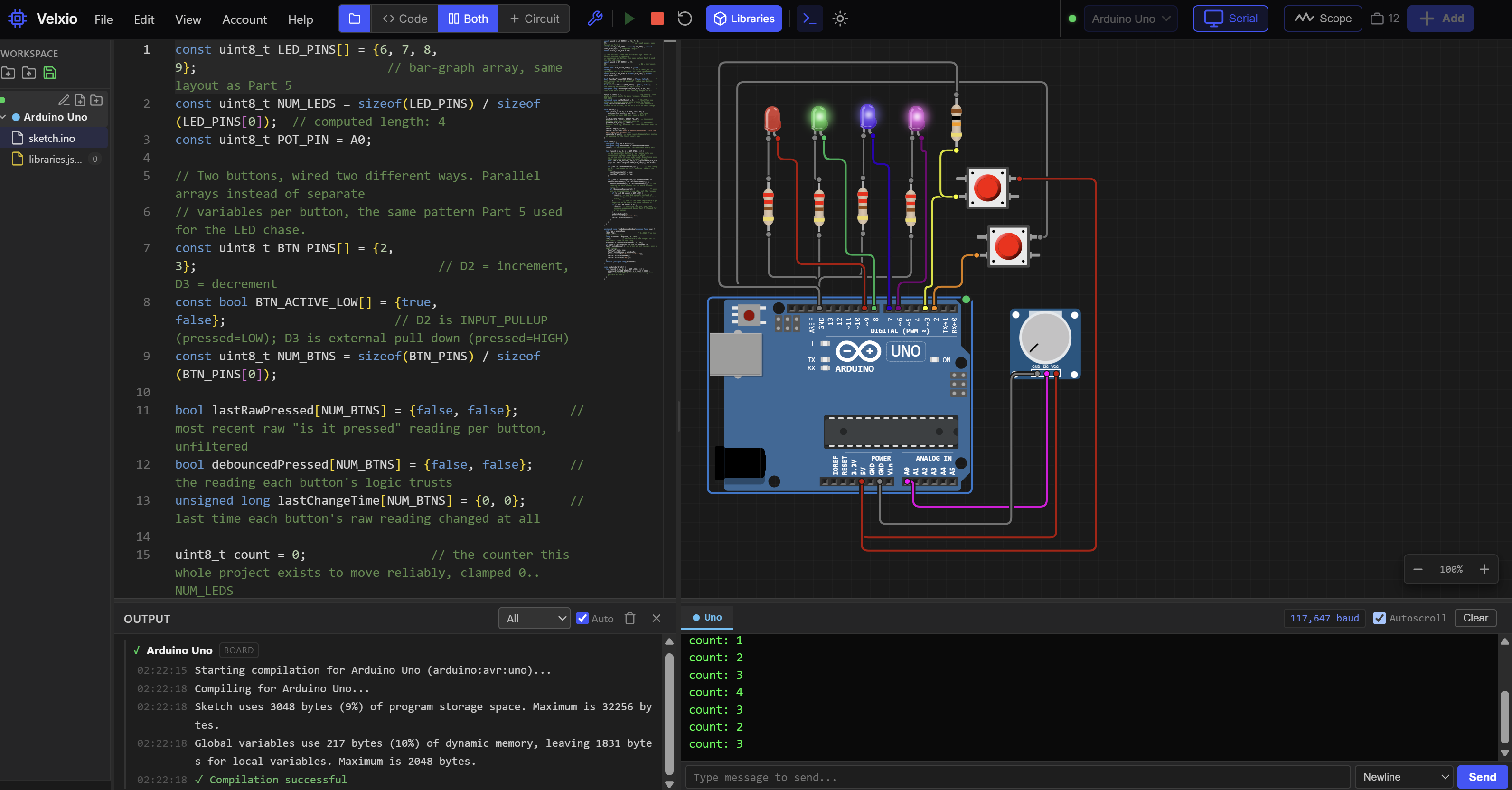
No hardware on hand? You can still build this one. Jump to the Lab embed in the practical project section below and run this whole build right in your browser.
Not every encoder lists its pins in the same order. Modules sold under names such as KY-040 print CLK, DT, SW, +, and GND, and different boards can arrange them differently, while bare encoders use A, B, and a common C plus a separate pair for the button. Match pins by their printed labels, never by position, and check that yours has an integrated push button. Then measure your encoder’s counts per detent before copying the value used here.
Before wiring: match pins by their printed labels. On a module, CLK is channel A, DT is channel B, SW is the button, + is power, and GND is the common return. A bare encoder has no + pin: its center terminal C is the common contact, and the separate pair of pins on the other side is the button. Either way the common connection goes to GND, and only a module’s + pin takes 5V. The sketch enables the Uno’s internal pull-ups on A, B, and the button, so it works with both kinds.
Exercise 1: Observe the Four A/B States
- You will: Turn the encoder slowly and print each new two-bit A/B state.
- Parts: Arduino Uno, breadboard, jumper wires, and the rotary encoder.
- Wiring: Connect CLK (channel A) to D2, DT (channel B) to D3, and GND (the center terminal C on a bare encoder) to GND. If your encoder has a + pin, connect it to 5V. Leave the button disconnected for now.
- Sketch:
const uint8_t ENCODER_A_PIN = 2;  // CLK (terminal A)
const uint8_t ENCODER_B_PIN = 3;  // DT (terminal B)

uint8_t previousState = 0;  // compare against the last state so each change prints once

uint8_t readEncoderState() {
  uint8_t aState = digitalRead(ENCODER_A_PIN);
  uint8_t bState = digitalRead(ENCODER_B_PIN);
  return (aState << 1) | bState;  // pack A and B into one 0-3 number: A in bit 1, B in bit 0
}

void printEncoderState(uint8_t state) {
  Serial.print(F("A="));
  Serial.print((state >> 1) & 0x01);  // shift A down to bit 0 and mask off the rest
  Serial.print(F("  B="));
  Serial.print(state & 0x01);  // bit 0 holds B
  Serial.print(F("  state="));
  Serial.print((state >> 1) & 0x01);  // A first, so the state reads as AB
  Serial.println(state & 0x01);
}

void setup() {
  pinMode(ENCODER_A_PIN, INPUT_PULLUP);  // the encoder only ever connects to GND, so the pins need pull-ups
  pinMode(ENCODER_B_PIN, INPUT_PULLUP);
  Serial.begin(115200);
  Serial.println(F("Exercise 1: turn one detent slowly and watch the AB sequence."));
  previousState = readEncoderState();  // read the real starting state so the first print isn't a false change
  printEncoderState(previousState);
}

void loop() {
  uint8_t currentState = readEncoderState();

  if (currentState != previousState) {
    printEncoderState(currentState);
    previousState = currentState;
  }
}- What to notice: One slow clockwise detent should visit
11, 01, 00, 10, 11with this exact part and orientation. Turning back should reverse the order. You may see repeated or reversed neighboring states from bounce. - If it fails: A channel stuck at 0 usually means that outer terminal is shorted to C or placed in the wrong breadboard row. A channel stuck at 1 usually means its jumper is open.
Exercise 2: Try the One-Channel Shortcut
- You will: Interrupt on the falling edge of A, read B, and produce a signed direction count with the beginner shortcut.
- Parts: Same circuit as Exercise 1.
- Wiring: Unchanged. A remains D2, B remains D3, and C remains GND.
- Sketch:
const uint8_t ENCODER_A_PIN = 2;  // channel A: the interrupt pin
const uint8_t ENCODER_B_PIN = 3;  // channel B: read inside A's ISR, no interrupt of its own

volatile int32_t position = 0;  // volatile: written in the ISR, read in loop()
int32_t lastPrintedPosition = 0;

void setup() {
  pinMode(ENCODER_A_PIN, INPUT_PULLUP);  // the encoder only ever connects to GND, so the pins need pull-ups
  pinMode(ENCODER_B_PIN, INPUT_PULLUP);
  Serial.begin(115200);
  Serial.println(F("Exercise 2: one-channel direction shortcut."));

  attachInterrupt(
    digitalPinToInterrupt(ENCODER_A_PIN),
    channelAFallingISR,
    FALLING  // one edge per A cycle, so each pulse counts once
  );
}

void loop() {
  noInterrupts();  // copy the 32-bit counter with interrupts off, or the ISR can change it mid-read
  int32_t positionSnapshot = position;
  interrupts();

  if (positionSnapshot != lastPrintedPosition) {
    Serial.print(F("Shortcut count: "));
    Serial.println(positionSnapshot);
    lastPrintedPosition = positionSnapshot;
  }
}

void channelAFallingISR() {
  if (digitalRead(ENCODER_B_PIN) == HIGH) {  // B still HIGH as A falls means clockwise, on this wiring
    position++;
  }
  else {
    position--;
  }
}- What to notice: The count should increase in one direction and decrease in the other, usually about once per detent on this encoder. Turn back and forth near a detent and watch for the shortcut’s bounce sensitivity.
- If it fails: If the sign is reversed, swap A and B or reverse the two actions in the ISR. Direction names are a wiring convention, not a safety issue.
Exercise 3: Decode Every Legal Transition
- You will: Put both channels on
CHANGEinterrupts and decode previous/current state pairs through a 16-entry lookup table. - Parts: Same circuit.
- Wiring: Unchanged. Both external-interrupt pins are now active.
- Sketch:
const uint8_t ENCODER_A_PIN = 2;  // channel A, interrupt pin D2
const uint8_t ENCODER_B_PIN = 3;  // channel B, interrupt pin D3

const int8_t TRANSITION_TABLE[16] = {
   0, -1, +1,  0,  // from 00: 01 reverse, 10 forward, 11 illegal
  +1,  0,  0, -1,  // from 01: 00 forward, 11 reverse, 10 illegal
  -1,  0,  0, +1,  // from 10: 00 reverse, 11 forward, 01 illegal
   0, +1, -1,  0  // from 11: 01 forward, 10 reverse, 00 illegal
};

volatile int32_t rawPosition = 0;  // ISR-owned, so volatile
volatile uint16_t invalidTransitions = 0;
volatile uint8_t previousEncoderState = 0;

int32_t lastPrintedPosition = 0;
uint16_t lastPrintedInvalidCount = 0;

uint8_t readEncoderState() {
  uint8_t aState = digitalRead(ENCODER_A_PIN);
  uint8_t bState = digitalRead(ENCODER_B_PIN);
  return (aState << 1) | bState;  // A in bit 1, B in bit 0
}

void setup() {
  pinMode(ENCODER_A_PIN, INPUT_PULLUP);  // the encoder only ever connects to GND, so the pins need pull-ups
  pinMode(ENCODER_B_PIN, INPUT_PULLUP);
  Serial.begin(115200);
  Serial.println(F("Exercise 3: full two-channel transition-table decoder."));

  previousEncoderState = readEncoderState();  // read the starting state before interrupts can fire, or the first change is misjudged
  attachInterrupt(digitalPinToInterrupt(ENCODER_A_PIN), updateEncoderISR, CHANGE);  // CHANGE on both pins, because the table needs every edge
  attachInterrupt(digitalPinToInterrupt(ENCODER_B_PIN), updateEncoderISR, CHANGE);
}

void loop() {
  noInterrupts();  // copy both multi-byte values with interrupts off
  int32_t positionSnapshot = rawPosition;
  uint16_t invalidSnapshot = invalidTransitions;
  interrupts();

  if (positionSnapshot != lastPrintedPosition || invalidSnapshot != lastPrintedInvalidCount) {
    Serial.print(F("Raw transitions: "));
    Serial.print(positionSnapshot);
    Serial.print(F("  Illegal jumps: "));
    Serial.println(invalidSnapshot);
    lastPrintedPosition = positionSnapshot;
    lastPrintedInvalidCount = invalidSnapshot;
  }
}

void updateEncoderISR() {
  uint8_t currentState = readEncoderState();
  uint8_t tableIndex = (previousEncoderState << 2) | currentState;  // previous state in the high two bits, current in the low two: a 0-15 table index
  int8_t movement = TRANSITION_TABLE[tableIndex];

  if (movement != 0) {
    rawPosition += movement;
  }
  else if (currentState != previousEncoderState) {  // state changed but the table says 0: a two-bit jump, usually bounce or a missed edge
    invalidTransitions++;
  }

  previousEncoderState = currentState;  // always resync, even after an illegal jump, so one glitch can't derail every later lookup
}- What to notice: One physical detent should now change the raw position by about four. The illegal-jump count should stay low during careful turns. It may rise if you spin quickly, disturb the wiring, or the contacts bounce across an unseen intermediate state.
- If it fails: A raw count that alternates without progressing usually means A and B are not both changing, or the encoder GND (terminal C on a bare encoder) is not firmly connected.
Exercise 4: Measure Counts per Detent
- You will: Compare raw transitions with normalized detents and configure one named scale value.
- Parts: Same circuit.
- Wiring: Unchanged.
- Sketch: Upload the sketch, start at a clear detent, and turn exactly five detents in one direction. Divide the raw change by five. Enter that result as
COUNTS_PER_DETENT, upload again, and repeat the test.
const uint8_t ENCODER_A_PIN = 2;  // channel A, interrupt pin D2
const uint8_t ENCODER_B_PIN = 3;  // channel B, interrupt pin D3
const int8_t COUNTS_PER_DETENT = 4;  // measure yours: it depends on the encoder and how many edges you count

const int8_t TRANSITION_TABLE[16] = {
   0, -1, +1,  0,  // from 00: 01 reverse, 10 forward
  +1,  0,  0, -1,  // from 01: 00 forward, 11 reverse
  -1,  0,  0, +1,  // from 10: 00 reverse, 11 forward
   0, +1, -1,  0  // from 11: 01 forward, 10 reverse
};

volatile int32_t rawPosition = 0;
volatile uint8_t previousEncoderState = 0;
int32_t lastPrintedRawPosition = 0;

uint8_t readEncoderState() {
  uint8_t aState = digitalRead(ENCODER_A_PIN);
  uint8_t bState = digitalRead(ENCODER_B_PIN);
  return (aState << 1) | bState;  // A in bit 1, B in bit 0
}

void setup() {
  pinMode(ENCODER_A_PIN, INPUT_PULLUP);  // the encoder only ever connects to GND, so the pins need pull-ups
  pinMode(ENCODER_B_PIN, INPUT_PULLUP);
  Serial.begin(115200);
  Serial.println(F("Exercise 4: compare raw transitions with normalized detents."));

  previousEncoderState = readEncoderState();  // read the starting state before interrupts can fire
  attachInterrupt(digitalPinToInterrupt(ENCODER_A_PIN), updateEncoderISR, CHANGE);  // CHANGE on both pins, because the table needs every edge
  attachInterrupt(digitalPinToInterrupt(ENCODER_B_PIN), updateEncoderISR, CHANGE);
}

void loop() {
  noInterrupts();  // copy the 32-bit counter with interrupts off
  int32_t rawSnapshot = rawPosition;
  interrupts();

  if (rawSnapshot != lastPrintedRawPosition) {
    int32_t detentPosition = rawSnapshot / COUNTS_PER_DETENT;  // raw counts divided by counts per click gives detents
    Serial.print(F("Raw: "));
    Serial.print(rawSnapshot);
    Serial.print(F("  Detents: "));
    Serial.println(detentPosition);
    lastPrintedRawPosition = rawSnapshot;
  }
}

void updateEncoderISR() {
  uint8_t currentState = readEncoderState();
  uint8_t tableIndex = (previousEncoderState << 2) | currentState;  // previous state in the high bits, current in the low bits
  int8_t movement = TRANSITION_TABLE[tableIndex];
  rawPosition += movement;
  previousEncoderState = currentState;
}- What to notice: This encoder should measure close to four raw counts per detent with this x4 decoder. A different encoder or decoding method may produce one, two, or four.
- If it fails: If normalized detents lag or jump at unexpected places, test ten detents instead of one. A longer measurement makes occasional bounce easier to distinguish from the real scale factor.
You now have every piece the final dial needs: visible A/B states, a useful but limited shortcut, complete two-channel decoding, a measured scale factor, and a diagnostic that distinguishes legal motion from two-bit jumps.
Practical Project: Interrupt-Driven Position and Direction Dial
Done looks like: turn the shaft clockwise and the raw count rises while the clockwise LED lights. Turn it counterclockwise and the count falls while the other LED lights. The normalized detent value changes once for each measured physical click. Press the shaft, release it, and position resets to zero once without an extra encoder count. Fast turns remain responsive, and any rejected two-bit jumps appear in a separate diagnostic field instead of silently becoming position.
What You Will Build
- A full two-channel quadrature decoder using
CHANGEinterrupts on D2 and D3 - A signed raw transition count plus a position normalized by measured counts per detent
- Two LEDs that show the most recent clockwise or counterclockwise movement
- A D4 button reset handled with loop-based debounce from Part 6
- An illegal-transition counter that helps separate decoding trouble from display trouble
- Rate-limited Serial output that stays outside the ISR
Components Needed
Everything is in the Bill of Materials above: the Uno, breadboard and jumpers, rotary encoder, two LEDs, and two 220 Ω resistors. The reset button is built into the encoder shaft, so no separate tactile switch is required.
Lab Embed
Wiring
| Part or Signal | Connection | Purpose |
|---|---|---|
| Encoder CLK (channel A; terminal A on a bare encoder) | Arduino D2 | Quadrature channel A and external interrupt |
| Encoder DT (channel B; terminal B on a bare encoder) | Arduino D3 | Quadrature channel B and external interrupt |
| Encoder GND (terminal C on a bare encoder) | Arduino GND | Common contact for both encoder channels |
| Encoder + (modules only) | Arduino 5V | Powers the module’s own pull-up resistors; bare encoders have no + pin |
| Encoder SW (the button) | Arduino D4 | Active-low reset input with INPUT_PULLUP |
| Encoder button, second terminal (bare encoders only) | Arduino GND | Completes the button circuit when pressed; on a module the button already shares the GND pin |
| Clockwise LED anode | D8 through a 220 Ω resistor | Shows the most recent positive transition |
| Clockwise LED cathode | GND | LED return path |
| Counterclockwise LED anode | D9 through a 220 Ω resistor | Shows the most recent negative transition |
| Counterclockwise LED cathode | GND | LED return path |
Check this before powering the board: GND goes to GND, never 5V, and the + pin on a module is the only encoder pin that takes 5V. The sketch supplies pull-ups inside the Uno for A, B, and the button, so a module’s own pull-ups are a bonus, not a requirement. If you have a bare encoder and look at its three-pin side from the terminal side in the datasheet orientation, the terminals read B, C, A from left to right, and the separate pair on the other side is the button. Match pins by printed label, not by position.
The Sketch
const uint8_t ENCODER_A_PIN = 2;  // CLK (terminal A)
const uint8_t ENCODER_B_PIN = 3;  // DT (terminal B)
const uint8_t RESET_BUTTON_PIN = 4;  // SW on a module; on a bare encoder either button terminal works, with the other to GND
const uint8_t CLOCKWISE_LED_PIN = 8;  // lit by the most recent clockwise movement
const uint8_t COUNTERCLOCKWISE_LED_PIN = 9;  // lit by the most recent counterclockwise movement

const int8_t COUNTS_PER_DETENT = 4;  // 4 counts per click when decoding every edge; measure yours (Exercise 4)
const unsigned long DEBOUNCE_MS = 25;  // long enough to ride out switch bounce
const unsigned long REPORT_INTERVAL_MS = 50;  // caps Serial at 20 lines per second so printing can't crowd out loop()

const int8_t TRANSITION_TABLE[16] = {
   0, -1, +1,  0,  // from 00: 01 reverse, 10 forward, 11 illegal
  +1,  0,  0, -1,  // from 01: 00 forward, 11 reverse, 10 illegal
  -1,  0,  0, +1,  // from 10: 00 reverse, 11 forward, 01 illegal
   0, +1, -1,  0  // from 11: 01 forward, 10 reverse, 00 illegal
};

volatile int32_t rawPosition = 0;  // volatile: the ISR writes these, loop() reads them
volatile uint16_t invalidTransitions = 0;
volatile uint8_t previousEncoderState = 0;
volatile int8_t lastDirection = 0;

bool lastButtonReading = HIGH;
bool stableButtonState = HIGH;  // the debounced state, used for the reset action
unsigned long buttonChangedAt = 0;
unsigned long lastReportAt = 0;
int32_t lastReportedRawPosition = 0;
uint16_t lastReportedInvalidCount = 0;
bool forceReport = true;  // print once at startup and after a reset, even if nothing moved

uint8_t readEncoderState() {
  uint8_t aState = digitalRead(ENCODER_A_PIN);
  uint8_t bState = digitalRead(ENCODER_B_PIN);
  return (aState << 1) | bState;  // A in bit 1, B in bit 0
}

void setup() {
  pinMode(ENCODER_A_PIN, INPUT_PULLUP);  // the encoder only ever connects to GND, so the pins need pull-ups
  pinMode(ENCODER_B_PIN, INPUT_PULLUP);
  pinMode(RESET_BUTTON_PIN, INPUT_PULLUP);  // pressing the shaft connects D4 to GND
  pinMode(CLOCKWISE_LED_PIN, OUTPUT);
  pinMode(COUNTERCLOCKWISE_LED_PIN, OUTPUT);
  digitalWrite(CLOCKWISE_LED_PIN, LOW);
  digitalWrite(COUNTERCLOCKWISE_LED_PIN, LOW);

  previousEncoderState = readEncoderState();  // read the starting state before interrupts can fire
  attachInterrupt(digitalPinToInterrupt(ENCODER_A_PIN), updateEncoderISR, CHANGE);  // CHANGE on both pins, because the table needs every edge
  attachInterrupt(digitalPinToInterrupt(ENCODER_B_PIN), updateEncoderISR, CHANGE);

  Serial.begin(115200);
  Serial.println(F("Part 9 position and direction dial."));
  Serial.println(F("Output: raw transitions | normalized detents | direction | illegal jumps"));
}

void loop() {
  unsigned long now = millis();
  updateResetButton(now);  // debounce in loop(): a button is slow, and ISRs should stay tiny
  reportEncoderState(now);
}

void updateResetButton(unsigned long now) {
  bool buttonReading = digitalRead(RESET_BUTTON_PIN);

  if (buttonReading != lastButtonReading) {  // any raw change restarts the stable-time clock
    lastButtonReading = buttonReading;
    buttonChangedAt = now;
  }

  if (now - buttonChangedAt >= DEBOUNCE_MS && buttonReading != stableButtonState) {
    stableButtonState = buttonReading;

    if (stableButtonState == LOW) {  // reset on the press, not the release
      resetPosition();
    }
  }
}

void resetPosition() {
  noInterrupts();  // stop the ISR from changing these while they're cleared
  rawPosition = 0;
  invalidTransitions = 0;
  lastDirection = 0;  // zero direction turns both LEDs off
  interrupts();

  forceReport = true;  // redraw the output even though nothing moved
}

void reportEncoderState(unsigned long now) {
  if (now - lastReportAt < REPORT_INTERVAL_MS) {  // rate limit, so Serial output can't crowd out loop()
    return;
  }
  lastReportAt = now;

  noInterrupts();  // copy the multi-byte values with interrupts off
  int32_t rawSnapshot = rawPosition;
  uint16_t invalidSnapshot = invalidTransitions;
  int8_t directionSnapshot = lastDirection;
  interrupts();  // back on before the LEDs and Serial, which are slow

  digitalWrite(CLOCKWISE_LED_PIN, directionSnapshot > 0 ? HIGH : LOW);
  digitalWrite(COUNTERCLOCKWISE_LED_PIN, directionSnapshot < 0 ? HIGH : LOW);

  bool positionChanged = rawSnapshot != lastReportedRawPosition;
  bool diagnosticChanged = invalidSnapshot != lastReportedInvalidCount;
  if (!forceReport && !positionChanged && !diagnosticChanged) {  // an idle dial prints nothing, so the monitor stays readable
    return;
  }

  int32_t detentPosition = rawSnapshot / COUNTS_PER_DETENT;  // raw counts divided by counts per click gives detents
  Serial.print(F("Raw: "));
  Serial.print(rawSnapshot);
  Serial.print(F(" | Detents: "));
  Serial.print(detentPosition);
  Serial.print(F(" | Direction: "));

  if (directionSnapshot > 0) {  // positive means clockwise on this wiring
    Serial.print(F("CW"));
  }
  else if (directionSnapshot < 0) {
    Serial.print(F("CCW"));
  }
  else {
    Serial.print(F("none"));
  }

  Serial.print(F(" | Illegal jumps: "));
  Serial.println(invalidSnapshot);

  lastReportedRawPosition = rawSnapshot;
  lastReportedInvalidCount = invalidSnapshot;
  forceReport = false;
}

void updateEncoderISR() {
  uint8_t currentState = readEncoderState();
  uint8_t tableIndex = (previousEncoderState << 2) | currentState;  // previous state in the high bits, current in the low bits
  int8_t movement = TRANSITION_TABLE[tableIndex];

  if (movement != 0) {
    rawPosition += movement;
    lastDirection = movement;
  }
  else if (currentState != previousEncoderState) {  // state changed but the table says 0: a two-bit jump, usually bounce or a missed edge
    invalidTransitions++;
  }

  previousEncoderState = currentState;  // always resync, even after an illegal jump, so one glitch can't derail every later lookup
}
The wiring table and code constants match signal by signal: A (CLK) is D2, B (DT) is D3, reset (SW) is D4, the clockwise LED is D8, and the counterclockwise LED is D9. The encoder GND, both LED cathodes, and, on a bare encoder, the second button terminal share GND.
What Is Happening
setup() enables pull-ups on A, B, and the button. It reads the actual A/B state before attaching either interrupt. That initialization matters. If the sketch guessed a previous state, the first real edge could be compared against a state the encoder never occupied and appear as an illegal jump.
Both channels call updateEncoderISR() on every change. The ISR reads the current two-bit state, joins it with the previous state, and uses the 16-entry array to find +1, -1, or 0. Legal movement updates the raw position and most recent direction. A changed state with a zero table entry increments the illegal-transition diagnostic. The ISR then saves the current state and returns.
loop() handles everything slower. updateResetButton() applies the Part 6 stable-time debounce method to D4. Pressing the shaft clears position, direction, and the diagnostic counter inside one short critical section. There is no delay(), so button handling and reporting never intentionally block encoder interrupts.
reportEncoderState() runs at most once every 50 milliseconds. It briefly pauses interrupts, copies the shared multi-byte values, and restores interrupts before touching the LEDs or Serial port. That rate limit keeps a fast turn from producing hundreds of long text lines per second. The raw count still changes at full interrupt speed between reports.
The Serial line deliberately shows both Raw and Detents. Raw is the signed x4 transition count. Detents is raw divided by COUNTS_PER_DETENT. If your measured encoder produces two counts per click, change that one constant to 2. Do not change the transition table to make the display look right.
If the Project Fails the Done Test
Turn one detent slowly while watching Raw. If Raw does not walk through four same-direction counts, return to Exercise 1 and verify the A/B sequence before inspecting any LED or reset logic. This follows the Part 7 rule: reduce the system to the earliest observation that is already wrong. If raw transitions are correct but Detents is wrong, the wiring and decoder work. Only the scale factor needs attention.
Troubleshooting
| Symptom | Likely Cause | Fix |
|---|---|---|
| Count moves in the opposite direction | A and B are swapped, or your viewing direction differs from the convention used here | Swap the D2 and D3 channel wires, or reverse the signs in the transition table and keep the labels consistent |
| Count jumps by multiple values | You are viewing raw x4 transitions, contact bounce is adding legal back-and-forth steps, or wiring is loose | Compare Raw with Detents, reseat A/B/C, and watch the illegal-jump counter while turning one detent slowly |
| Count changes while the shaft appears stationary | A or B is floating because INPUT_PULLUP is missing, C is open, or a breadboard contact is intermittent | Confirm both channel pin modes, connect C firmly to GND, and check that the encoder legs enter separate breadboard rows |
| Slow turns work but fast turns lose position | One channel is still polled, only A has an interrupt, the ISR contains slow work, or interrupts are disabled too long | Use CHANGE interrupts on both D2 and D3, remove Serial and LED work from the ISR, and keep critical sections to copies only |
| One direction works and the other does not | One channel is stuck, the shortcut is sampling B at a noisy instant, or the table was edited incorrectly | Run Exercise 1 and confirm both legal sequences, then restore the published 16 table values |
| Position changes when the encoder pushbutton is pressed | Pressing the shaft flexes a loose breadboard connection, or a switch terminal was mistaken for A, B, or C | Brace the encoder, identify the three-pin encoder side and two-pin switch side from the datasheet, and move any loose jumper |
| One detent produces two or four counts | The decoder is counting more than one edge per physical detent | This is expected for x2 or x4 decoding. Measure several detents and set COUNTS_PER_DETENT to the observed value |
| Encoder is completely unresponsive | GND (or C on a bare encoder) is not grounded, A/B are on the wrong pins, or pins were matched by position instead of printed label | Wire CLK/A to D2, DT/B to D3, and GND to GND, then verify both pins change with Exercise 1 |
| Serial output makes behavior erratic or sluggish | The sketch prints on every interrupt or prints from inside the ISR | Print only copied snapshots from loop() and keep the 50 ms report interval or make it longer |
| Illegal-jump count climbs rapidly | Both bits appear to change between samples because an edge is missed, the common connection is poor, or the channel labels are wrong | Turn slowly, verify the four-state sequence, shorten any long critical section, and inspect the exact encoder pinout |
| Reset fires several times or never fires | The integrated button is not on D4/GND, or debounce state was moved into the encoder ISR | Keep the switch on ordinary input D4 with INPUT_PULLUP and leave the Part 6 debounce function in loop() |
| Raw count is good but normalized position is wrong | COUNTS_PER_DETENT was copied from another encoder or another decode mode | Measure the raw change across five or ten physical detents and replace the constant with that average |
Where This Fits in the Series
You can now treat two digital inputs as one time-ordered signal, extract direction from phase order, distinguish raw transitions from physical detents, and use a previous/current-state table to reject impossible two-bit jumps. That is more than counting pulses. It is dependable quadrature input with a visible diagnostic path when the hardware disagrees.
Series: Part 5: Arrays, Strings, and Data in C++ supplied the lookup-table idea. Part 6: Digital I/O You Can Trust supplied pull-ups and loop-based debounce. Part 7: Systematic Debugging supplied the measure-first troubleshooting method. Part 8: Interrupts: Reacting Without Polling supplied attachInterrupt(), ISR discipline, volatile, and safe multi-byte copying. This chapter combines those earlier skills around a two-channel encoder.
Catalog: The comprehensive external-interrupt guide remains the refresher for board-specific interrupt pins, trigger modes, sleep/wake examples, and other interrupt applications. An encoder-plus-OLED menu system and a volume-knob project are planned supporting pieces, but they are not live and this chapter does not depend on them.
Wrap-Up and What’s Next
An incremental encoder does not hand the Arduino a ready-made position. It supplies two staggered digital channels. Their order reveals direction, their transitions build relative position, and the relationship between electrical transitions and mechanical detents determines how the result should be scaled.
The one-channel shortcut is a useful first look at phase order. The complete decoder watches both channels, remembers the previous state, accepts legal Gray-code movement, and rejects impossible two-bit jumps. That protection improves reliability, but it does not erase every legal transition caused by mechanical bounce. Measuring the real hardware and keeping an invalid-transition diagnostic remain part of the job.
Next up, Part 10: Analog Measurement That Isn't a Lie. Part 9 decoded digital transitions into position and direction. Part 10 asks what happens when the input is not simply HIGH or LOW and a noisy ADC number must become a trustworthy measurement.
Want to go deeper? Download the full eBook once the series is complete, and subscribe for the rest of the Arduino Mastery Series.
Hack The World and Make Awesome.


