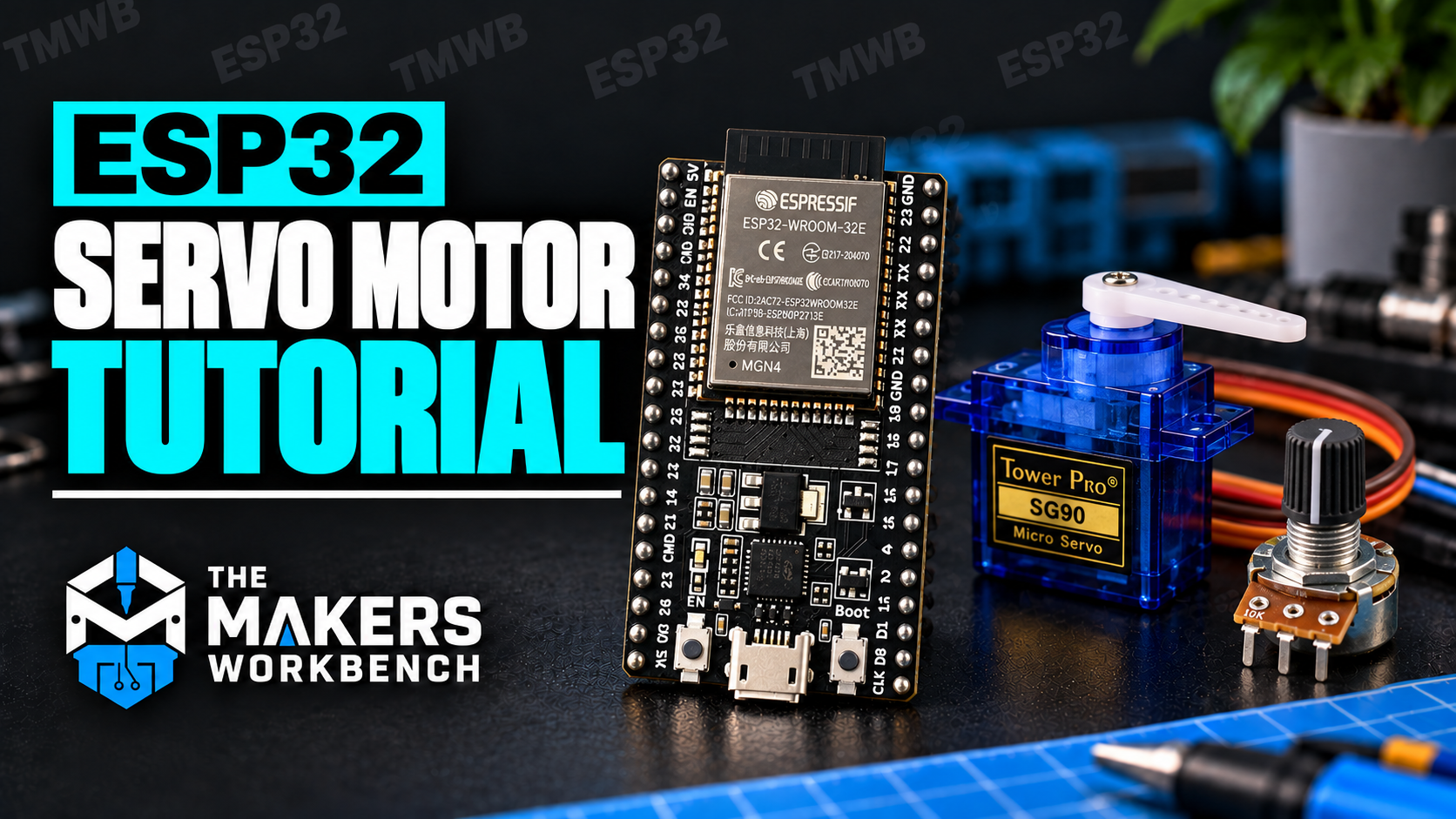
Think about the difference between a desk fan and the steering wheel of a car. A fan just spins as long as it has power, and you have no say in where any blade ends up. A steering wheel does something different. You turn it to a position, and the wheels go to that position and stay there until you say otherwise.
A servo motor is the steering-wheel kind of motor. You tell it an angle, it swings its arm to that angle, and it holds the position even if you push against it. That's why servos move robot arms, camera gimbals, model airplane flaps, and the little door on a pet feeder.
In this tutorial we'll open up a servo to see why it can do that, learn the strange little signal you use to command it, and wire one to an ESP32 (a small, inexpensive computer-on-a-chip with built-in Wi-Fi; we're using the ESP32-DevKitC board). Along the way we'll cover power, which is where most servo projects go wrong, and then build a project where a knob steers the servo in real time, either on a breadboard or in The Makers Workbench Electronics Lab.
What You'll Learn
- What is inside a servo, and how it knows where its arm is
- What a PWM signal is, and how pulse width sets the angle
- Which wire does what, and how to power a servo without crashing your ESP32
- Why the ESP32 uses the ESP32Servo library, and how to install it
- How an ADC turns a knob's position into a number, and how
map()turns that number into an angle - How to stop a servo from jittering
What Is Inside a Servo Motor?
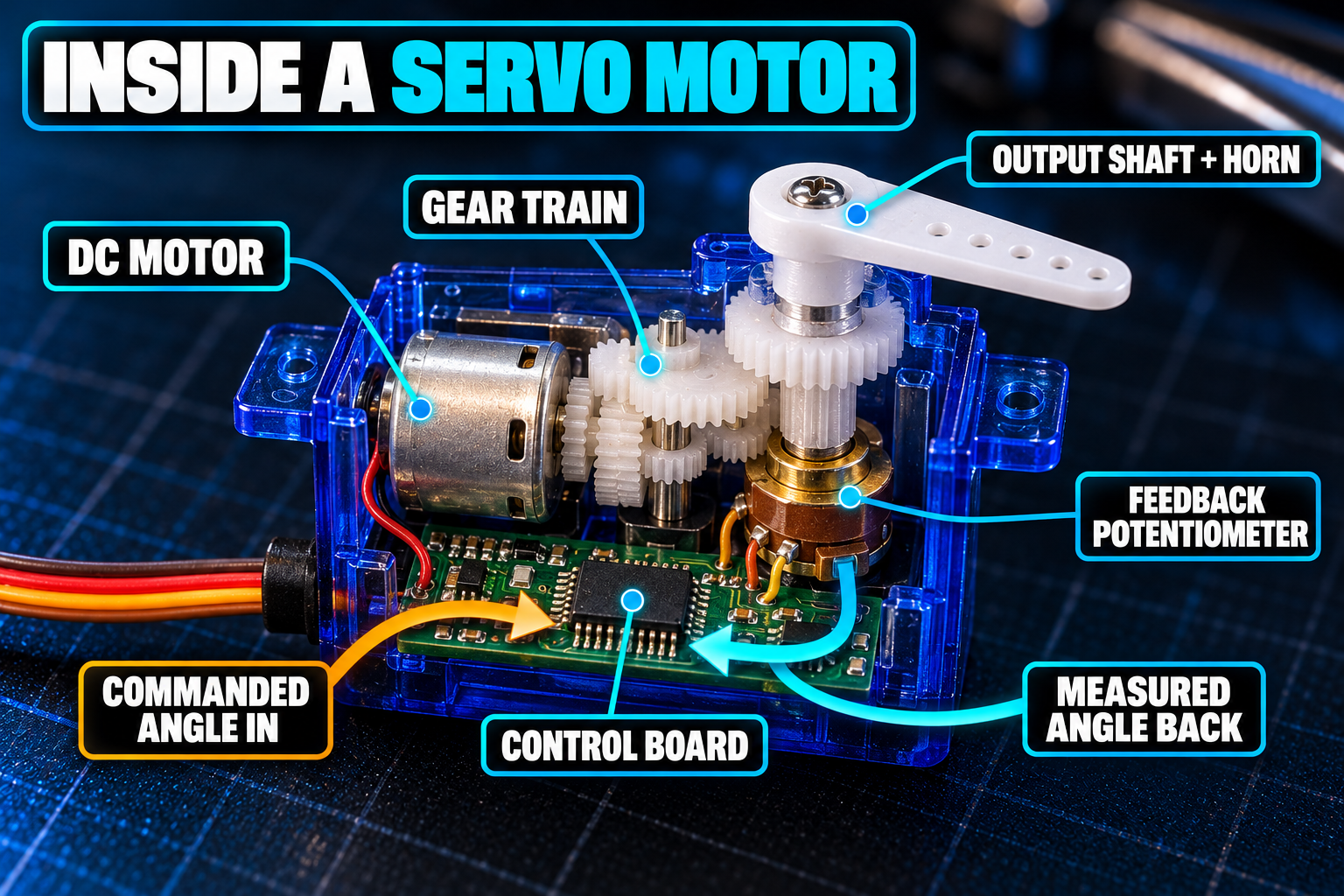
Crack open a small hobby servo like the SG90 and you'll find four parts:
- A small DC motor, which spins when you give it electricity.
- A gearbox, a set of small plastic or metal wheels with teeth. It trades the motor's high speed for strength, so the output shaft turns slowly but with real force.
- A potentiometer (a knob-style variable resistor) attached to the output shaft. As the arm turns, the potentiometer's value changes, so the servo always knows where its arm is.
- A tiny control circuit that compares the angle you asked for with the angle the potentiometer reports.
If the two disagree, the circuit runs the motor toward the target. When they match, it stops. If something pushes the arm away, the mismatch returns and the motor pushes back. Engineers call this a closed loop (the output is measured and fed back in). Cruise control in a car works the same way: it keeps checking your speed against the speed you set.
How Do You Tell a Servo What Angle to Go To?
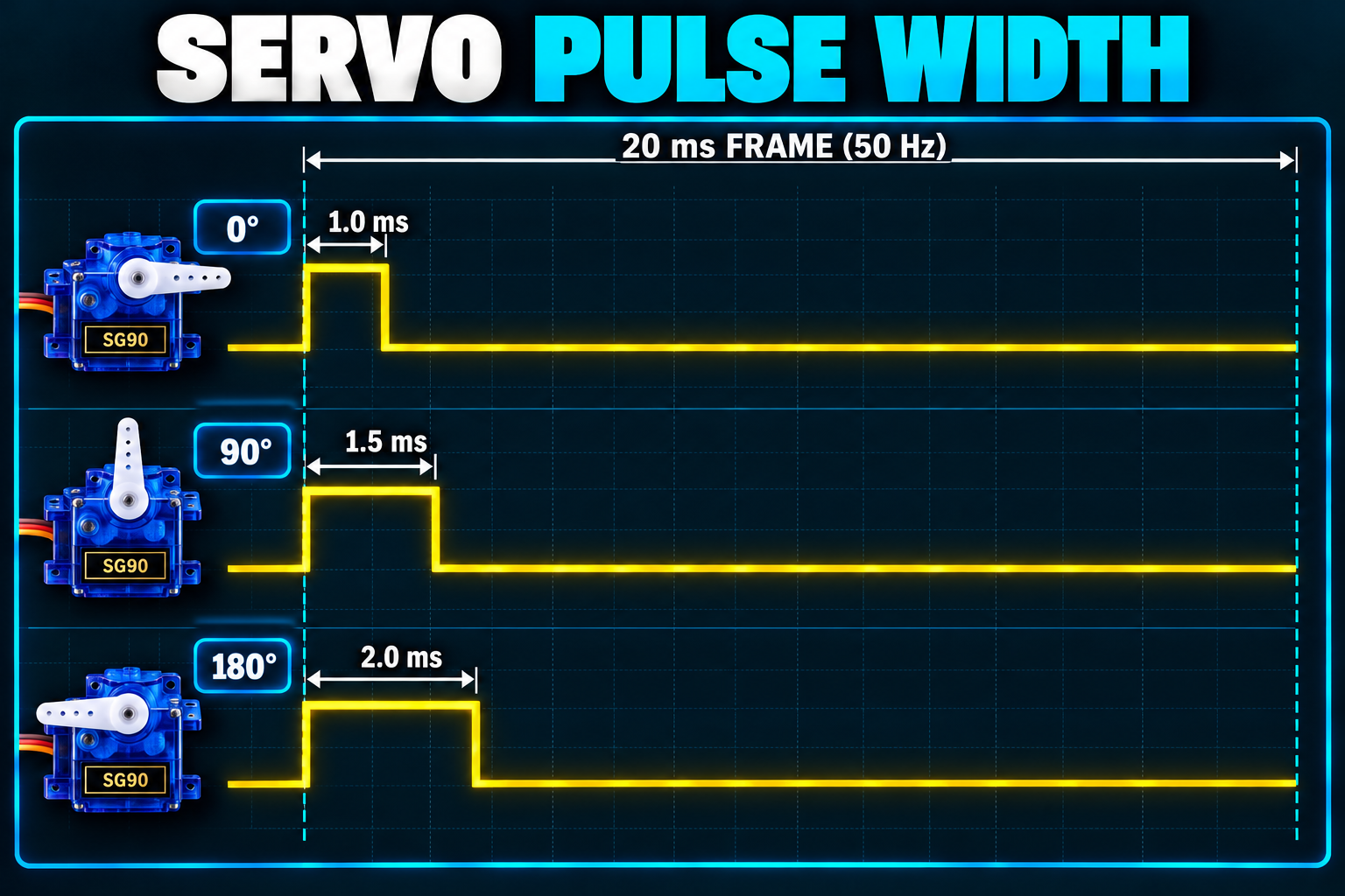
A hobby servo has three wires, and the commanding happens on one of them. You send a repeating pulse, and the width of the pulse (how long the pin stays HIGH) is the message. This scheme is called PWM, short for pulse width modulation.
A typical servo wants a new pulse every 20 milliseconds, which is 50 times per second (50 hertz, Hz). The width of each pulse picks the angle:
| Pulse width | Angle |
|---|---|
| About 1.0 ms | 0 degrees |
| About 1.5 ms | 90 degrees (center) |
| About 2.0 ms | 180 degrees |
(A millisecond, ms, is a thousandth of a second.) Real servos vary a little, and many SG90 units sweep the full range between roughly 0.5 ms and 2.4 ms. You'll see those two numbers, 500 and 2400 microseconds, in the code below.
Notice that the servo doesn't care about the voltage level or the duty cycle in the usual PWM sense. It only measures the pulse width, and the rest of the 20 ms is quiet.
What Do the Three Wires Do?
| Wire (typical colors) | Job |
|---|---|
| Red | V+, power in (4.8 to 6 V) |
| Brown or black | GND, ground |
| Orange or yellow | PWM, the signal you send the pulses on |
Colors aren't universal, so check your servo's listing. When in doubt, the center wire is almost always power.
How Do I Power a Servo from an ESP32?
Here's the trap. A servo's motor draws a lot more current than a GPIO pin can supply. A small SG90 pulls roughly 100 to 250 mA (a milliamp, mA, is a thousandth of an amp, the unit of electrical flow) while moving, and several hundred mA if the arm is blocked. An ESP32 GPIO pin can give a few tens of milliamps at best.
So never power a servo from a GPIO pin. Give it a real supply:
- One small servo (SG90 size): use the board's 5V pin (some boards label it VIN), which carries the 5 V coming from your USB cable.
- Bigger servos, or several at once: use a separate 5 to 6 V supply, and connect its ground to the ESP32's GND. Without a shared ground, the signal pulses have no common reference and the servo behaves randomly.
WARNING: if your ESP32 keeps rebooting whenever the servo moves, you're seeing a brownout. The servo's surge pulls the supply voltage down and the ESP32 resets. Use a better USB cable or port, or give the servo its own supply.
The signal wire is gentler. Most hobby servos accept the ESP32's 3.3 V pulses just fine.
Why Do I Need a Library?
I like to show the hard way before the shortcut, so you know what the shortcut saves you. You could make the pulse yourself:
// The hard way: build the 1.5 ms "center" pulse by hand
digitalWrite(SERVO_PIN, HIGH);   // start the pulse
delayMicroseconds(1500);         // hold it HIGH for 1500 microseconds (1.5 ms)
digitalWrite(SERVO_PIN, LOW);    // end the pulse
delay(18);                       // wait out the rest of the 20 ms frame
This works if you repeat it forever. But your whole program is stuck inside those delay() calls, the timing wobbles whenever the ESP32 does other work, and the servo drifts the instant you stop sending pulses.
The ESP32 has hardware built for this. Its LEDC peripheral (a built-in circuit that produces steady pulses by itself, with no help from your code) can output the pulse train in the background. The ESP32Servo library wraps that hardware in a simple Servo object. The older Arduino Servo library was written for different chips, so it isn't the right tool on the ESP32.
To install it: in the Arduino IDE, open Sketch > Include Library > Manage Libraries, type ESP32Servo in the search box, and click Install. If you ever download a library as a .zip instead, use Sketch > Include Library > Add .ZIP Library, and restart the IDE afterward so it notices the new files.
How Does the ESP32 Read a Knob?
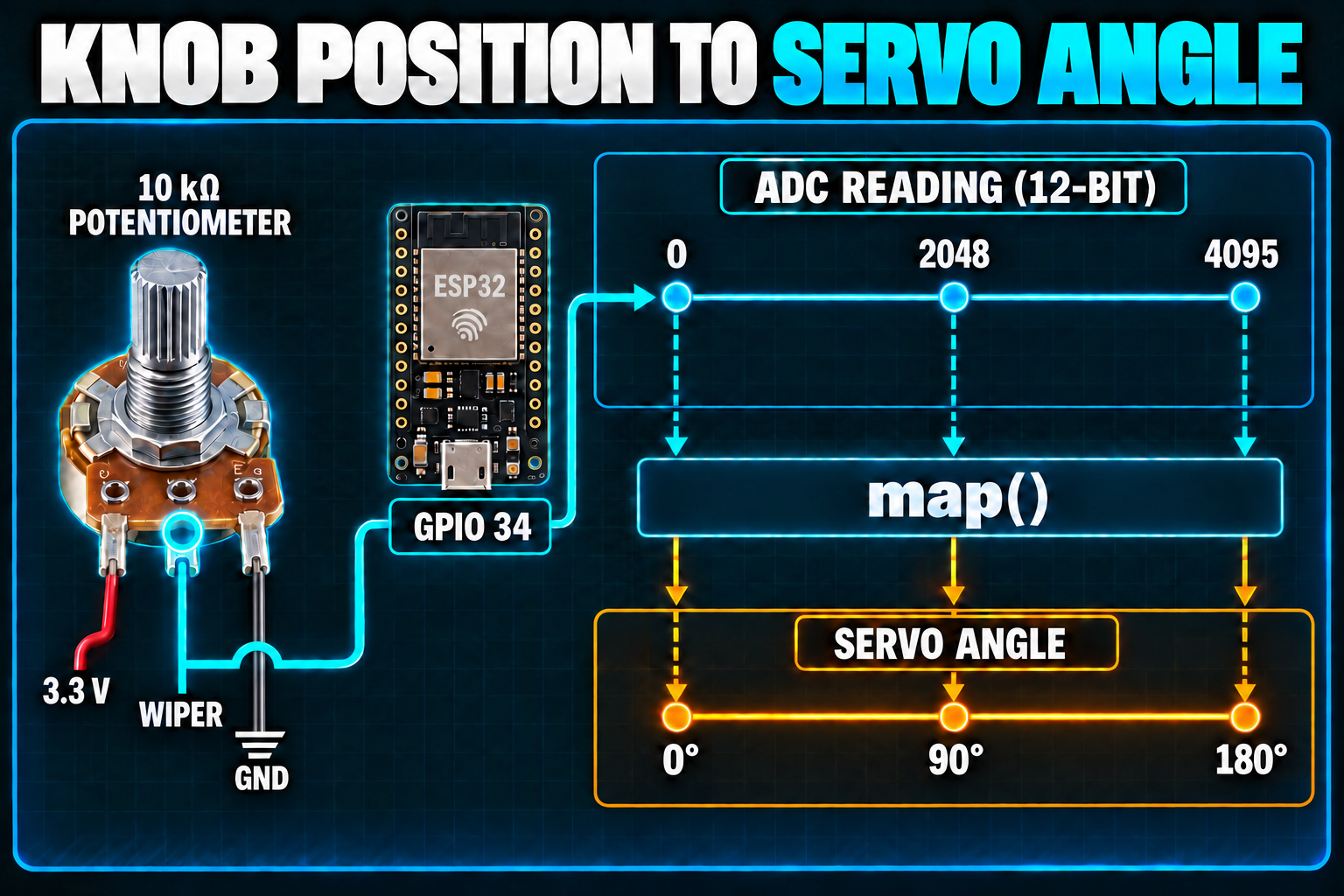
For the project, a knob (a potentiometer) will steer the servo. A potentiometer has three legs. The outer two connect to 3.3 V and ground, and the middle leg, called the wiper, slides along a resistive track as you turn the knob, outputting any voltage between the two.
The ESP32 reads that voltage with an ADC, an analog-to-digital converter (a circuit that turns a voltage into a whole number). The ESP32's ADC is 12-bit, so it reports numbers from 0 (0 V) to 4095 (3.3 V). An Arduino Uno stops at 1023, so the ESP32 is about four times finer.
To turn 0 to 4095 into 0 to 180 degrees, we use the Arduino function map(value, fromLow, fromHigh, toLow, toHigh), which scales a number from one range to another. A reading of 2048, the halfway point, comes out as 90 degrees.
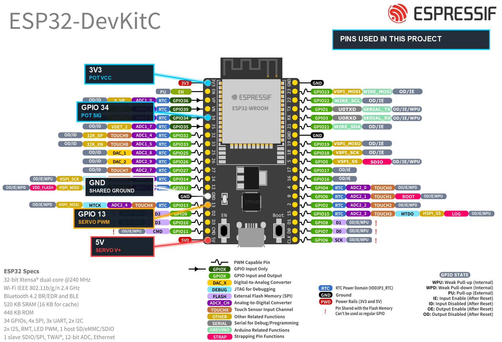
Two ESP32 details to know up front. We read the knob on GPIO 34, an input-only pin on ADC1, which is safe to use any time. (The pins on ADC2 stop working when Wi-Fi is on, which will bite you in a later project.) And ADC readings are a little noisy, so the sketch averages eight readings to keep the servo from twitching.
Bill of Materials
| Component | Description | Buy on Amazon | Buy on Temu | Buy on SparkFun | Buy on Seeed Studio | Datasheet |
|---|---|---|---|---|---|---|
| ESP32-DevKitC development board | Espressif's official ESP32 board (ESP32-WROOM module, Micro-USB, Wi-Fi and Bluetooth) | Amazon Link | Temu Link | Temu Link | Temu Link | ESP32 datasheet |
| SG90 micro servo | A 9 g hobby servo that runs on 5 V. The listing is a 4-pack, so you have spares. | Amazon Link | Temu Link | Temu Link | Temu Link | SG90 datasheet |
| 10 kΩ potentiometer | The knob that steers the servo | Amazon Link | Temu Link | SparkFun Link | N/A | N/A |
| Breadboard & jumper wires | For prototyping connections without soldering | Amazon Link | Temu Link | SparkFun Link | Seeed Link | N/A |
| USB data cable | Powers the ESP32 and uploads code. Make sure it carries data, not just power. | Amazon Link | Temu Link | SparkFun Link | Temu Link | N/A |
The products linked above may contain affiliate links. The Makers Workbench earns from qualifying purchases when these links are used.
How Do I Wire the Servo and Knob?
Here is the point-to-point wiring for the project. The ESP32's pins are labeled on the board, and the DevKitC pinout shows where each one sits.
| From | To | Why |
|---|---|---|
| Servo V+ (red) | ESP32 5V (labeled VIN on some boards) | 5 V power for the motor |
| Servo GND (brown or black) | ESP32 GND | Shared ground |
| Servo PWM (orange or yellow) | ESP32 GPIO 13 | Pulse signal from the ESP32 |
| Potentiometer outer leg 1 (VCC) | ESP32 3V3 | Top of the knob's voltage range |
| Potentiometer outer leg 2 (GND) | ESP32 GND | Bottom of the range |
| Potentiometer middle leg (SIG) | ESP32 GPIO 34 | The wiper, read by the ADC |
What Does the Full Sketch Look Like?
// Servo steered by a potentiometer on the ESP32
// Servo PWM to GPIO 13. Potentiometer wiper to GPIO 34.

#include <ESP32Servo.h>               // the library that drives servos from the ESP32's LEDC hardware

#define SERVO_PIN 13                  // GPIO 13 carries the pulse signal to the servo
#define POT_PIN   34                  // GPIO 34 reads the potentiometer (input-only ADC1 pin)

Servo myServo;                        // one Servo object stands for one physical servo

void setup() {
  Serial.begin(115200);               // start the Serial Monitor connection
  myServo.setPeriodHertz(50);         // send 50 pulses per second, which standard servos expect
  myServo.attach(SERVO_PIN, 500, 2400);  // pin, pulse width for 0 degrees (us), pulse width for 180 degrees (us)
  Serial.println("Servo and knob ready");
}

void loop() {
  long total = 0;                     // running total for averaging
  for (int i = 0; i < 8; i++) {       // take 8 quick readings
    total += analogRead(POT_PIN);     // add each 0 to 4095 reading to the total
  }
  int raw = total / 8;                // the average smooths out ADC noise

  int angle = map(raw, 0, 4095, 0, 180);  // scale 0-4095 down to 0-180 degrees
  myServo.write(angle);               // command the servo to that angle

  Serial.printf("Knob: %4d  Angle: %3d deg\n", raw, angle);  // show both numbers
  delay(20);                          // match the servo's 20 ms pulse cycle
}
The wiring table and this sketch agree: GPIO 13 for the servo and GPIO 34 for the knob. If you ever move a wire, change the matching #define and nothing else.
Try the Servo Project in the Lab
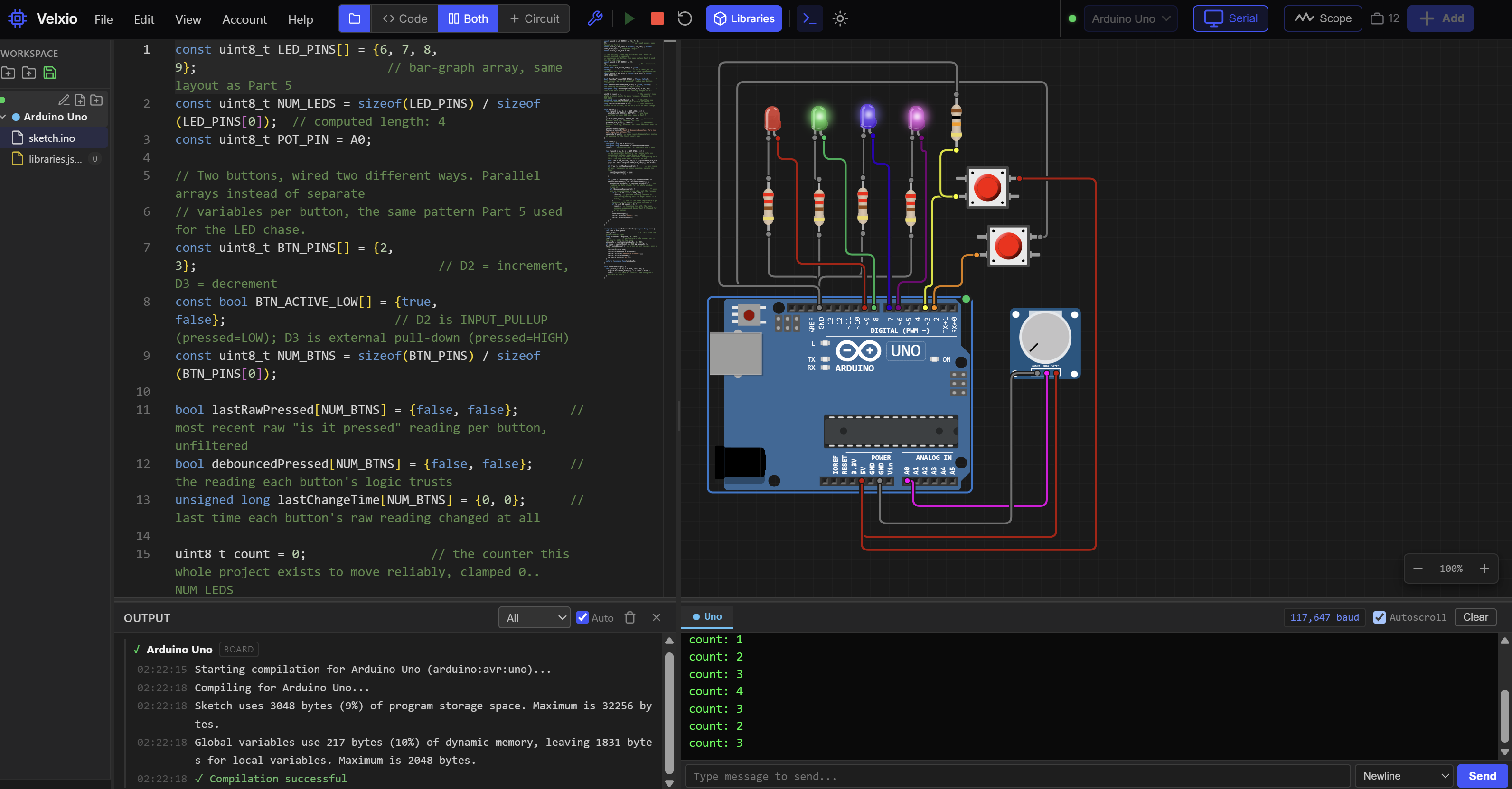
If you don't have the parts yet, build it in The Makers Workbench Electronics Lab. You'll need an ESP32, a servo, and a potentiometer, wired as in the table above.
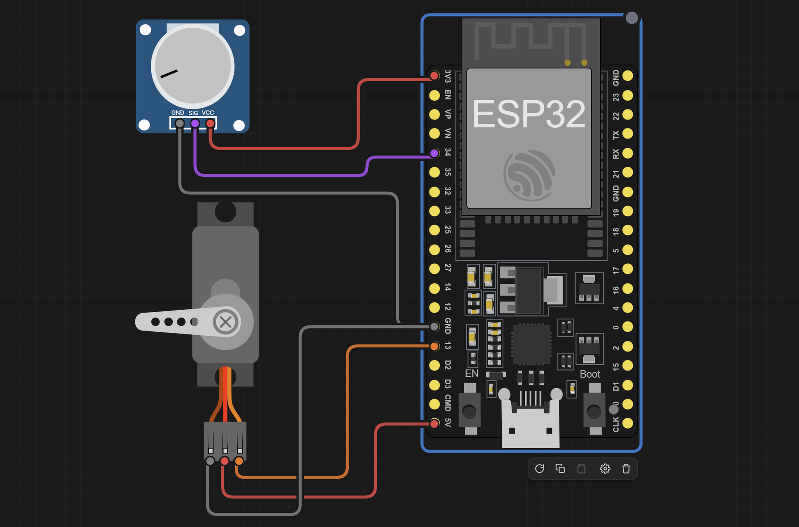
The Lab circuit is wired like this:
| From | To | Why |
|---|---|---|
| Servo V+ (red) | ESP32 5V | 5 V power for the motor |
| Servo GND (brown or black) | ESP32 GND | Shared ground |
| Servo PWM (orange or yellow) | ESP32 GPIO 13 | Pulse signal from the ESP32 |
| Potentiometer VCC | ESP32 3V3 | Top of the knob's voltage range |
| Potentiometer GND | ESP32 GND | Bottom of the range |
| Potentiometer SIG (middle) | ESP32 GPIO 34 | The wiper, read by the ADC |
Load the sketch and press Run. Drag the potentiometer's knob, and the servo's arm should sweep to follow it, while the Serial Monitor prints the raw reading and the angle. Turn the knob to the middle and you should see about 2048 and 90 degrees. The ESP32Servo library will install itself in the Lab on first run, so give the first compile a moment.
Why Is My Servo Jittering or Misbehaving?
- Constant twitching. Usually ADC noise or weak power. The eight-reading average helps, and a good USB cable helps more.
- Buzzing at the ends of the sweep. The arm is hitting its mechanical stop, so the motor strains against it. Narrow the
attach()limits, say to 600 and 2300, until the buzzing stops. - The angle is off. Servos vary. Adjust the two numbers in
attach()until 0 and 180 land where you expect. - The ESP32 reboots. See the brownout warning above.
Conclusion
A servo is a motor with a built-in sense of position, and you steer it with the width of a pulse sent 50 times a second. You now know what's inside one, why it needs its own power source, why the ESP32 uses the ESP32Servo library, and how a 12-bit ADC and map() turn a knob into an angle.
Next in the series: the I²C bus, where several sensors share just two wires.