Think about the light switch on your wall. You press a small plastic lever with one finger, and a lamp on the other side of the room turns on. Your finger never touches the lamp or the wires that power it. It just moves a switch, and the switch decides whether electricity flows.
An ESP32 has the same problem you have when you stand in front of a very heavy machine: it can decide when something should turn on, but it can't supply the muscle to power it. Each of its pins can push out only a tiny amount of electricity, and a fan, a pump, a lamp, or a solenoid (a coil of wire that pulls a metal plunger when current flows through it, like the valve in a washing machine) needs far more than that. What we need is a robot finger that the ESP32 can tell to flip a switch for it.
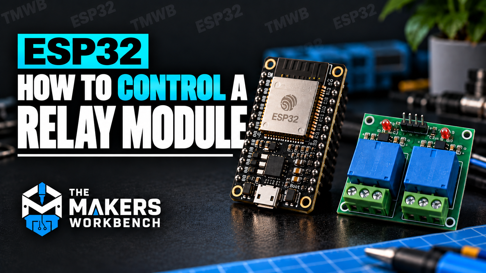
That robot finger is called a relay, and in this tutorial we'll connect one to an ESP32 and control it from the Arduino IDE, the free program you use to write code and send it to the board. (An ESP32 is a small, inexpensive computer-on-a-chip with built-in Wi-Fi and Bluetooth. The board we're using is the ESP32-DevKitC.) We'll start by clicking the relay on and off, then move on to timed switching, switching without freezing the rest of your program, and making the relay react to a temperature reading the way a thermostat does.
Just as important, we'll spend time on what the hardware is doing, because the code is the easy part. Three lines of Arduino code will click a relay. Knowing which terminal to wire your load to, why so many relay modules turn on when you send them a LOW signal, and whether a module that was designed for 5 V boards will behave with your 3.3 V ESP32 is what keeps a project from misbehaving at 2 a.m.
Safety first. Relays are famous for switching mains electricity (the 120 V or 240 V coming out of your wall outlet), but you do not need mains voltage to learn how a relay works, and nothing in this tutorial uses it. Every example here switches a small, safe, low-voltage DC load (a 12 V fan). Mains wiring can kill you and can start fires. It calls for properly rated parts, an insulated enclosure, correct wire sizes, fuses, and real electrical training. If you eventually want to switch mains power, buy a finished, certified product built for that job, or work with a qualified electrician. Learn the ideas here first, with a fan.
What You'll Learn
By the end of this tutorial, you will know how to:
- Explain what an electromechanical relay is and how it works inside
- Explain why an ESP32 needs an interface to control higher-power loads
- Tell the control side of a relay module from the switched side
- Use the COM, NO, and NC terminals, and choose between NO and NC
- Tell the difference between a bare relay and a relay module
- Explain what the flyback diode, the optocoupler, and the JD-VCC jumper do
- Work out whether a relay module will behave with the ESP32's 3.3 V signals
- Explain what active-HIGH and active-LOW mean, and handle both in code
- Wire a relay module and a 12 V load to an ESP32
- Turn a relay on and off from Arduino code, and from the Serial Monitor
- Switch a relay on a timer without freezing your program
- Read a relay's contact rating and know why the type of load matters
- Use hysteresis to stop a relay from chattering
- Choose between a relay, a MOSFET, and a solid-state relay
- Troubleshoot common relay problems
What Is a Relay?
A relay is an electrically operated switch.
Remember the electromagnet from a science class, a coil of wire that turns into a magnet while current flows through it? A relay is built around exactly that. Inside a typical relay there are two separate parts:
- A coil, which is that electromagnet.
- A set of contacts, which are small metal pads that either touch each other (letting current through) or sit apart (blocking it).
When current flows through the coil, it pulls on a small metal lever called the armature. The armature rocks, and as it moves it pushes the contacts from one position to another. When the current stops, a spring pulls the armature back to where it started. That sharp "click" you hear when a relay switches is the armature snapping from one position to the other.
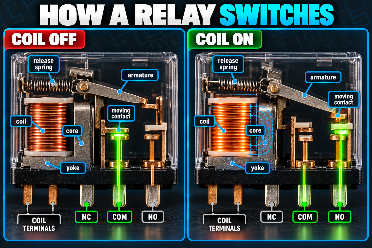
The key idea is that the coil and the contacts are electrically separate. The coil is on the control side, and the contacts are on the switched side. Electricity never travels from one to the other. Only the magnetic pull does.
Control Circuit                    Switched Circuit

ESP32 ---> Driver ---> [ COIL ]    [ CONTACTS ] ---> Load
                          :             :
                          :.. magnetic ..:
                              pull only
That separation is why the ESP32 doesn't have to supply the load's current. If a relay is switching a 12 V fan that draws 0.2 A, those 0.2 A flow through the relay's contacts and never through the ESP32. The ESP32 only controls the small circuit that energizes the coil.
Why Can't the ESP32 Control the Load Directly?
Two numbers explain this, and I'll define both so we're on the same page. Voltage (measured in volts, V) is the electrical "push" available in a circuit, like water pressure in a pipe. Current (measured in amps, A, or milliamps, mA, where 1,000 mA equals 1 A) is how much electricity is actually flowing, like how much water moves through the pipe per second.
An ESP32 pin, called a GPIO (General Purpose Input/Output, one of the numbered pins along the edge of the board that your code can control), puts out 3.3 V and can supply only a few tens of milliamps. Espressif's datasheet (linked in the Bill of Materials) gives the exact limits, and the safe habit is to stay well below them. A fan might want 200 mA or more at 12 V. A pump or a solenoid can want an amp or more. A relay coil by itself needs around 70 mA at 5 V. None of those fit comfortably through a GPIO.
If you connect a load that asks for too much current to a GPIO pin, one of two things happens. The load doesn't work, or the pin (and eventually the chip behind it) gets damaged. The ESP32 can't be repaired, so the answer is to never ask the pin to do the heavy lifting in the first place.
So we put a switching device between the ESP32 and the load. A few kinds exist:
- A relay, which switches with a physical moving contact
- A MOSFET or transistor, which are electronic switches with no moving parts
- A solid-state relay (SSR), a packaged electronic switch that behaves like a relay
- A motor driver, a chip built to power motors specifically
We'll use a relay in this tutorial, and near the end I'll compare it with the others so you know when to pick something different.
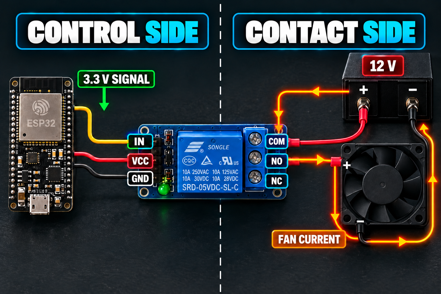
What Are the Control Side and the Contact Side of a Relay Module?
Soon we'll buy a relay module, which is a small circuit board with a relay on it, so it helps to know what its two halves look like.
The control side is the one that connects to your ESP32. On a single-channel module you'll find pins labeled something like:
VCC
GND
IN
A multi-channel module has one input per relay (IN1, IN2, IN3, IN4, and so on). The ESP32 changes the voltage on IN, and the module's circuitry takes that as the instruction to energize or release the relay.
The contact side is where your load connects. It's usually a row of screw terminals labeled:
NC
COM
NO
Those three terminals belong to the circuit being switched. Your ESP32 never connects to them. Understanding what they do is the single most useful thing in this tutorial, so let's go through them slowly.
What Do COM, NO, and NC Mean?
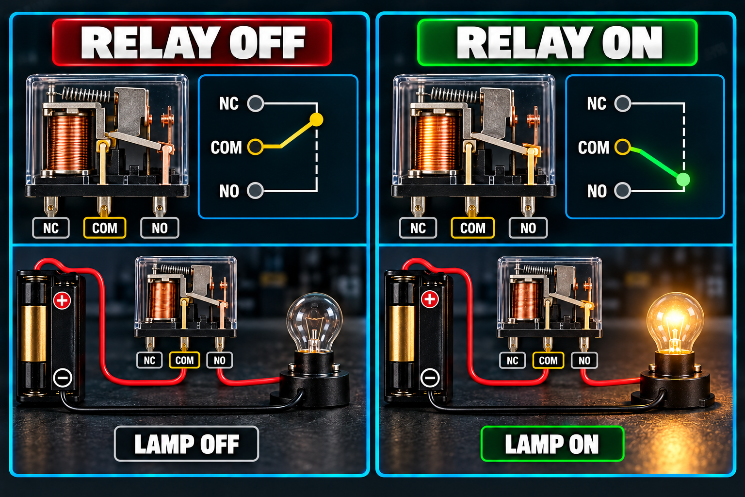
The most common relay has one single-pole double-throw (SPDT) set of contacts. That's a mouthful for something simple: one moving contact that can touch one of two stationary contacts, like a seesaw that is always resting on one end or the other. It gives you three terminals:
- COM is the common terminal. It's the seesaw's pivot, and the one that always connects to something.
- NO is normally open. It is not connected to COM while the relay is resting.
- NC is normally closed. It is connected to COM while the relay is resting.
"Normally" always means the relay's state when its coil has no power. So think of NO and NC as describing the relay at rest.
Relay off (coil not energized):
COM ---- NC      (connected)

COM      NO      (not connected)
Relay on (coil energized):
COM      NC      (not connected)

COM ---- NO      (connected)
When the coil gets power, the seesaw tips. COM lets go of NC and connects to NO instead.
Wiring a Load to NO (Normally Open)
For most projects, NO is the terminal you want. Suppose we want a fan to stay off until the ESP32 turns it on:
Supply +  ----  COM

NO  -------------  Fan +

Fan -  ----------  Supply -
At rest, COM and NO are not connected, so the circuit is broken and the fan is off. When the ESP32 energizes the relay, COM connects to NO, the circuit closes, and the fan runs.
Wiring a Load to NC (Normally Closed)
Sometimes you want the opposite. You might want something to run all the time and only stop when the ESP32 says so:
Supply +  ----  COM

NC  -------------  Load +

Load -  ----------  Supply -
At rest, COM connects to NC, so the load gets power. When the relay energizes, COM lets go of NC and the load turns off.
Which One Should I Pick?
Ask yourself what the circuit should do if the ESP32 loses power, crashes, or is being reset. A relay with no power on its coil is always at rest, so with NO wiring the load is off in that situation, and with NC wiring the load is on.
For a heater or a pump, off is almost always the safe answer, so you wire to NO. For something like a security light or a freezer alarm, you might deliberately want on, so you'd wire to NC. Pick the terminal for the situation where the controller fails, not for the situation where everything works.
What Do the Numbers Printed on a Relay Mean?
Pick up a relay and you'll see small text on its plastic case, often something like this:
SRD-05VDC-SL-C
10A 250VAC
10A 30VDC
There are two completely separate sets of information in there, and mixing them up is one of the most common beginner mistakes.
05VDCis the coil voltage. It says the coil is designed to run from 5 V DC (direct current, the steady kind of electricity you get from a battery or a USB port). This is the control side.10A 250VACand10A 30VDCare the contact ratings. They say the contacts can switch up to 10 amps at up to 250 V AC (alternating current, the back-and-forth kind from a wall outlet), or up to 10 amps at up to 30 V DC. This is the switched side.
So a "5 V relay" doesn't mean it can only switch 5 V. It means its coil wants 5 V. And a relay with contacts that can handle 250 V doesn't mean you should feed its coil 250 V. Never work out the coil voltage from the contact rating, or the other way around.
Why Contact Ratings Are Not the Whole Story
Those contact ratings come with fine print. They assume a specific kind of load under specific test conditions, so "10 A" on the case doesn't mean every 10 A load is safe.
Loads fall into rough families:
- Resistive loads, like a heater element or a plain LED lamp, draw about the same current from the moment you turn them on.
- Inductive loads, like motors, solenoids, and transformers, store energy in a magnetic field. They draw a big surge when they start, and they push back with a voltage spike when you switch them off.
- Capacitive loads, like some power supplies, can gulp a large burst of current for an instant when they first connect.
An old-style incandescent bulb is its own special case. Its filament has low resistance while it's cold, so it can draw many times its running current for the first fraction of a second. A motor can do the same thing at startup. The relay's contacts have to survive that surge, not just the number on the box. A common rule of thumb is to choose a relay rated for at least double the load's normal running current, and more than that for motors and lamps. Check the manufacturer's datasheet for the exact figures for each kind of load.
DC is harder on contacts than AC. AC current drops to zero 100 or 120 times every second, which helps extinguish the tiny electrical arc (a spark) that jumps across the gap as the contacts open. DC never drops to zero by itself, so the arc is harder to kill and can burn and weld the contacts over time. That's why the DC rating on the case (30 V) is so much lower than the AC rating (250 V), and why you shouldn't assume the AC figure applies to a DC load.
What Is the Difference Between a Bare Relay and a Relay Module?
A bare relay is a small box with a handful of pins sticking out the bottom. You can't hook one straight to an ESP32 pin, and here's the hard way to see why.
First, the coil needs around 70 mA, which is more than a GPIO should be asked to give. So you'd need a transistor in between, which is a tiny electronic switch where a small current at one pin controls a much larger current through the other two. You'd also need a resistor to set how hard the transistor's control pin gets driven.
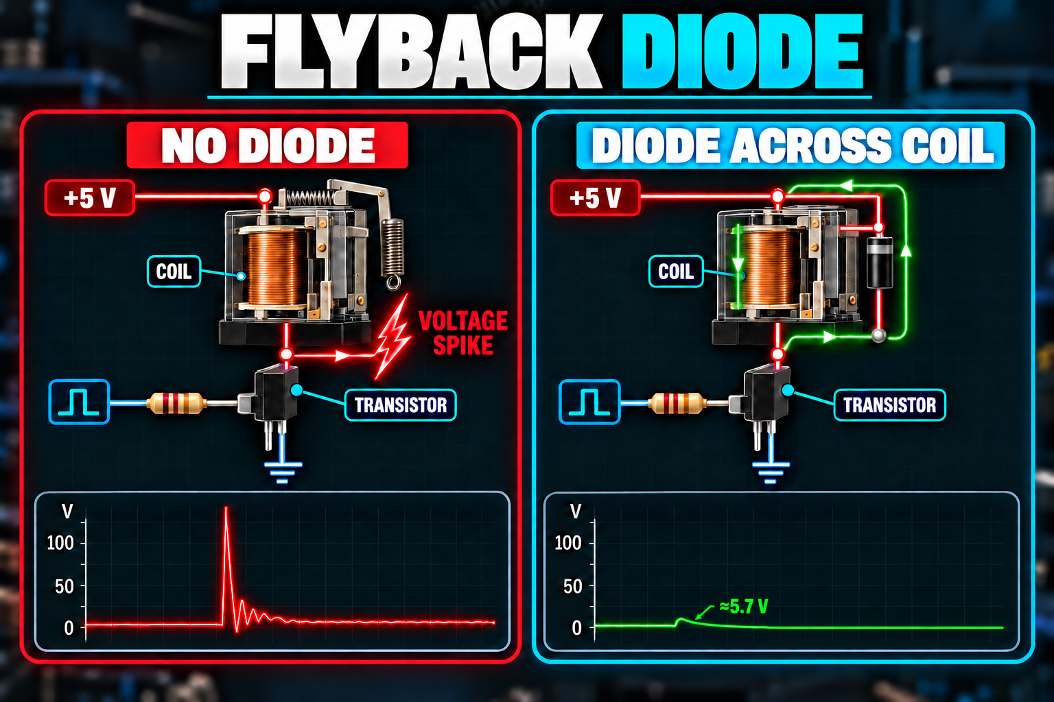
Second, the coil is an inductor, so when you cut its current the collapsing magnetic field produces a voltage spike that can be many times the supply voltage. That spike can destroy the transistor. You'd need a diode placed across the coil to give the spike somewhere harmless to go.
So a bare relay needs, at minimum, a transistor, a resistor, and a diode, all wired correctly, before the ESP32 can use it. Most people also add an LED to show when the relay is energized, and screw terminals for the load.
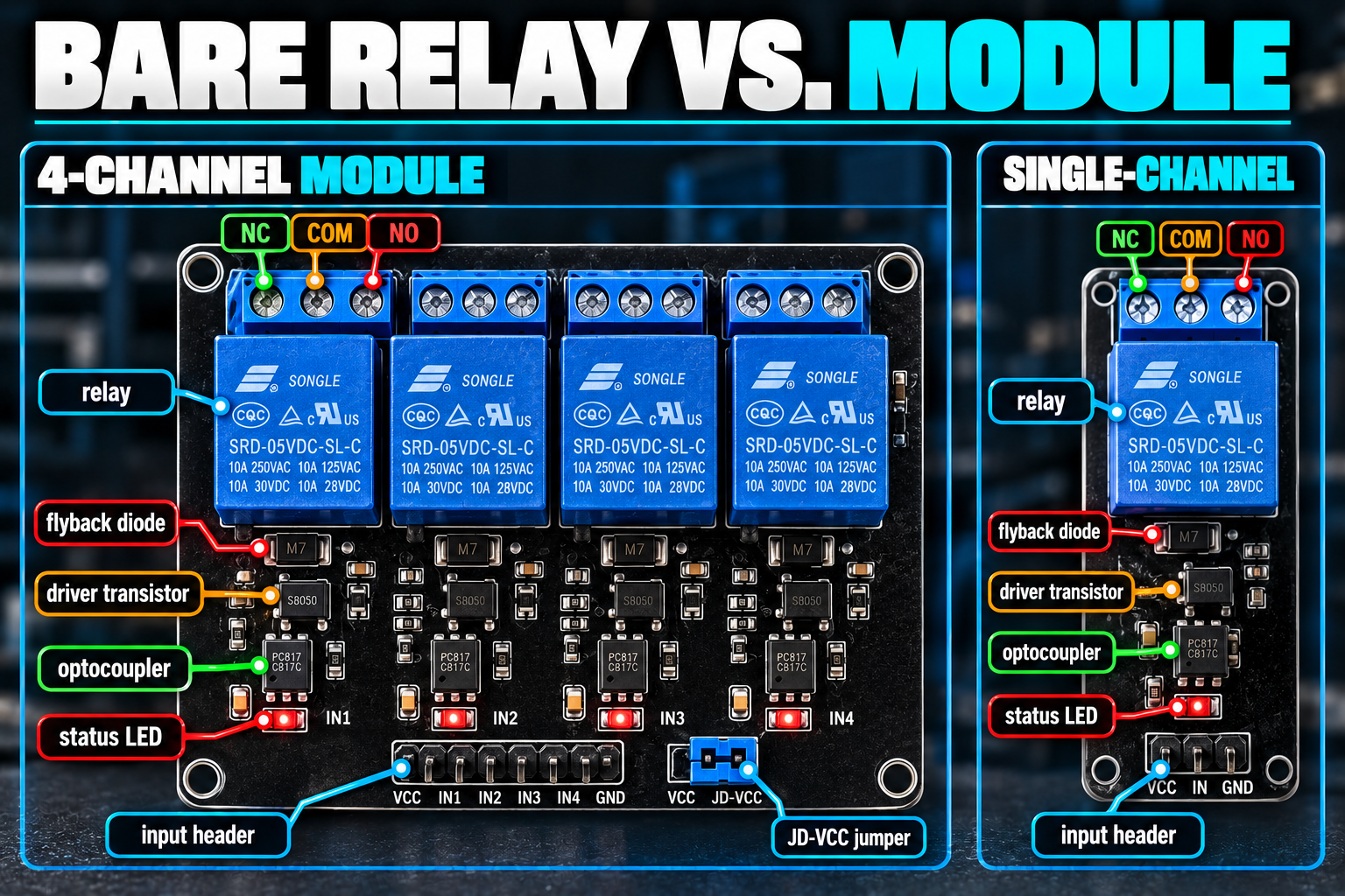
A relay module is that whole assembly already built on a small circuit board. A typical module has:
- The relay itself
- A driver transistor
- A flyback diode (that's the diode across the coil)
- A resistor on the input
- A status LED
- Screw terminals for COM, NO, and NC
- Header pins for VCC, GND, and the input
- On many boards, an optocoupler (we'll get to that shortly)
That's why we're using a module: all the parts that protect the ESP32 and the relay are done for you. If you'd like to build the bare-relay version yourself, the Electronics Lab section later in this tutorial does exactly that.
What Does the Flyback Diode Do?
Think about a long water pipe with fast-moving water in it. If you slam the valve shut, the water has nowhere to go and the pipe bangs and shudders. That's called water hammer, and it comes from all that moving mass being stopped instantly.
A coil has an electrical version of that problem. While current flows, energy is stored in its magnetic field. When the driver switches off, the field collapses, and the coil tries to keep the current flowing anyway. With nowhere to go, the voltage across the coil swings the opposite direction and can reach many times the supply voltage, enough to damage a transistor.
A flyback diode (a diode is a component that lets current flow in only one direction) is connected across the coil, pointing the "wrong" way for normal operation. While the relay is energized, the diode does nothing. When the coil switches off and tries to push current backward, the diode gives that current a short loop to circulate in until the energy fades out. It's the open pressure-relief valve on the pipe.
What Are Optocouplers and JD-VCC?
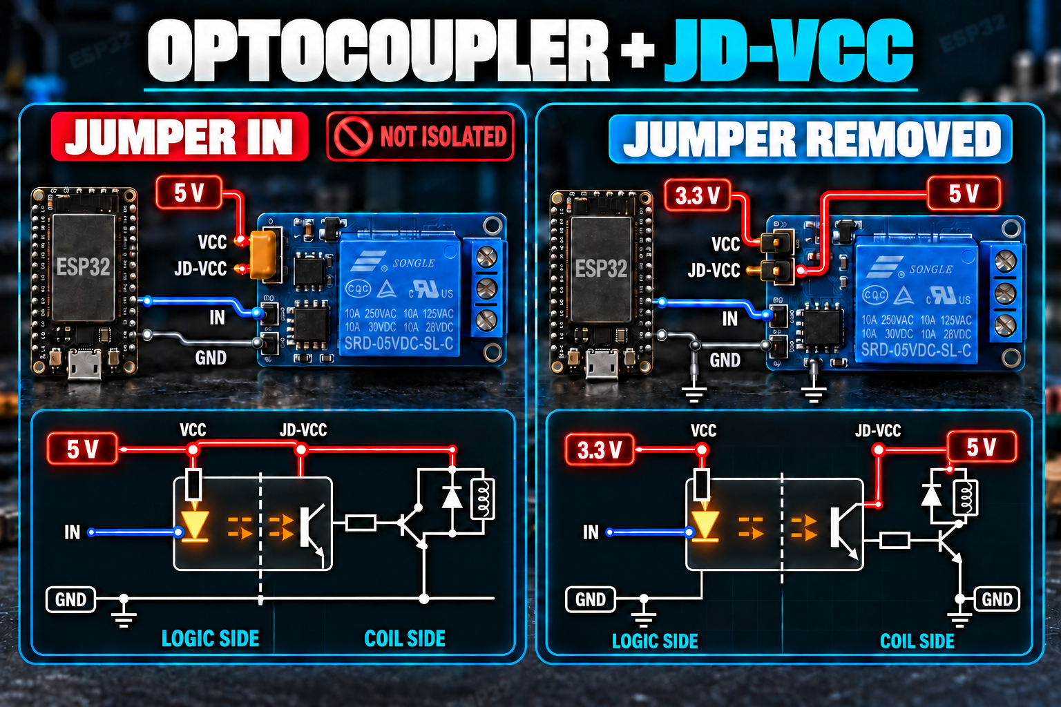
Many modules include an optocoupler, a small chip that passes a signal using light. Inside is an LED on one side and a light-sensitive switch on the other, with no electrical connection between them. When the LED lights up, the other side switches on. It lets a signal cross from one circuit to another without the two sharing a wire.
On a relay module the idea is that the ESP32 side talks to the relay side by light, so the two sides could in principle have separate power supplies and separate grounds. That separation (called isolation) protects your ESP32 from trouble on the relay side.
Here's the catch. Seeing an optocoupler on the board doesn't mean your wiring is isolated. Most modules connect the two sides back together with a jumper (a small plastic cap that bridges two pins) between a pin labeled VCC and one labeled JD-VCC:
VCCpowers the input side, which holds the LED inside the optocoupler.JD-VCCpowers the relay coil and its driver transistor.
With the jumper in place, one supply feeds both, and the isolation is gone. With the jumper off, you can power each side separately, and that is exactly what we'll do in this tutorial to solve a different problem, covered next. Real isolation also requires that the two sides share no ground, which we'll talk about in the wiring section. Designs vary, so when isolation matters, read the schematic for your exact module.
Will a 5 V Relay Module Work with the ESP32's 3.3 V Pins?
This is the part of relay projects where ESP32 owners most often get tripped up.
The ESP32's GPIO pins output 3.3 V. Many inexpensive relay modules were designed years ago for 5 V boards such as the classic Arduino Uno. Those modules might have VCC = 5 V and an input expecting 5 V logic. Does a 3.3 V signal work? Sometimes yes, sometimes it half works, and I can't tell you which one you have without a little investigation. Let me show you what to look for.
What Can Go Wrong
Take the most common kind of module, with an optocoupler, active-LOW, powered from 5 V with the jumper in place. The input pin connects through a resistor to the optocoupler's LED, whose other end sits at VCC (5 V). To switch the relay on, the input must be pulled down below VCC so current can flow through the LED.
- Input at 0 V (LOW): there's a full 5 V across the LED and resistor, plenty of current flows, the relay turns on. That's the case we want.
- Input at 5 V (HIGH): zero volts across the LED, no current, the relay is off. Perfect.
- Input at 3.3 V (HIGH from an ESP32): there's still about 1.7 V across the LED and resistor. An LED needs about 1.2 V before it lights, so a small current can still trickle through. On some modules that trickle is enough to keep the relay partly or fully on, even though the code says "off."
That's the symptom to watch for: the relay clicks on correctly when you drive the pin LOW, but won't release when you drive the pin HIGH. Sometimes it chatters or buzzes. It depends on the specific optocoupler and resistor on your board, so two modules that look identical can behave differently.
The Fix: Give the Logic Side 3.3 V
The cleanest solution uses that JD-VCC jumper. Remove the jumper, then:
- Feed
VCC(the logic side with the optocoupler's LED) from the ESP32's 3.3 V pin. - Feed
JD-VCC(the relay coil side) from 5 V.
Now when the ESP32 drives the input HIGH at 3.3 V, the LED has 3.3 V on both ends and sees no voltage difference at all. It turns off completely. When the pin goes LOW, there's 3.3 V across the LED and resistor, which is still plenty of current for a typical optocoupler to switch the relay's driver transistor on.
If your module has only three pins (VCC, GND, IN) and no JD-VCC, you can't split the supplies. Try it and watch for the symptom above. If the relay doesn't release, a fallback that often works is to switch the pin to a floating input instead of driving it HIGH. We'll look at that in the troubleshooting section.
Check Before You Connect
For any module you didn't buy specifically for 3.3 V, work through this list first:
| Question | Where to look |
|---|---|
| What is the relay's coil voltage? | The printed text on the relay case (5 V, 12 V, 24 V) |
| Is there an optocoupler? | A small 4-pin chip, usually printed PC817 or EL817 |
| Is there a VCC / JD-VCC jumper? | Next to the input header |
| Is it active-HIGH or active-LOW? | Product listing, or test it (see the next section) |
| Does the input draw only a few milliamps? | Optocoupler modules typically do; check the listing |
| Could the input pin end up near 5 V? | Only if you drive it from a 5 V source, which we won't |
If a module has a header jumper labeled "H/L" or "trigger level," that selects active-HIGH or active-LOW, which is a nice-to-have.
What Do Active-HIGH and Active-LOW Mean?
Many common relay modules are active-LOW. That means the relay turns on when the input is LOW and off when the input is HIGH:
IN = LOW   ->  Relay ON
IN = HIGH  ->  Relay OFF
If you're new to relays, this feels backward. You'd expect this line to turn the relay on:
digitalWrite(RELAY_PIN, HIGH);
On an active-LOW module, it does the opposite.
It's the optocoupler wiring that causes this. The LED inside is connected between VCC and the input pin, so it lights when the input is pulled down toward ground. Other modules (and bare transistor drivers like the one in our Lab) are active-HIGH, where HIGH turns the relay on, and LOW turns it off:
IN = HIGH  ->  Relay ON
IN = LOW   ->  Relay OFF
You need to know which kind you have. The easiest way is to run the first sketch in this tutorial and watch the relay's status LED and the click, which we'll do shortly. Later in the tutorial we'll set up the code so that a single line changes if you swap modules.

Bill of Materials
For this project you will need the parts below. We're using the ESP32-DevKitC, Espressif's own ESP32 development board, and Espressif's official ESP32-DevKitC documentation covers the board in full detail. The relay module is a 4-channel board. We only need one channel for this tutorial, but 4-channel modules are very common, include the JD-VCC jumper we want for the 3.3 V fix, and leave you three more relays for later projects.
| Component | Description | Buy on Amazon | Buy on Temu | Buy on SparkFun | Buy on Seeed Studio | Datasheet |
|---|---|---|---|---|---|---|
| ESP32-DevKitC development board | Espressif's official ESP32 development board (ESP32-WROOM module, Micro-USB, Wi-Fi and Bluetooth) | Amazon Link | Temu Link | Temu Link | Temu Link | ESP32 datasheet, DevKitC docs |
| 4-channel 5 V relay module (with optocouplers and a JD-VCC jumper) | One relay channel is used in this tutorial. Look for SRD-05VDC-SL-C relays and a VCC / JD-VCC / GND header. | Amazon Link | Temu Link | Temu Link | Temu Link | SRD-05VDC-SL-C relay datasheet |
| 12 V DC fan | A standard 12 V computer fan makes a safe, easy demo load (about 0.1 to 0.3 A). Use the fan's 12 V and ground wires only. | Amazon Link | Temu Link | Temu Link | Temu Link | N/A |
| 12 V DC power supply (1 A or more, wall adapter) | Powers the fan through the relay. Not the same as the ESP32's USB power. | Amazon Link | Amazon Link | Amazon Link | Amazon Link | N/A |
| Female DC power jack adapter | Lets you connect the wall adapter's barrel plug to your wiring | Amazon Link | Temu Link | Temu Link | Temu Link | N/A |
| 1N4001 diode | Protects against the fan's voltage spike when the relay opens | Amazon Link | Temu Link | Temu Link | Temu Link | 1N4001 to 1N4007 datasheet |
| 2N2222 NPN transistor | Only for the second Lab: it drives the relay coil by hand, the "hard way" build. A PN2222A is a pin-compatible equivalent. | Amazon Link | Temu Link | SparkFun Link | N/A | PN2222A datasheet |
| Breadboard & jumper wires | For prototyping connections without soldering | Amazon Link | Temu Link | SparkFun Link | Seeed Link | N/A |
| USB data cable | Powers the ESP32 and uploads your code. Match your board's connector (Micro-USB or USB-C), and make sure it carries data, not just power. | Amazon Link | Temu Link | SparkFun Link | Temu Link | N/A |
The products linked above may contain affiliate links. The Makers Workbench earns from qualifying purchases when these links are used.
A few notes before you order or start wiring:
About the relay module. Product listings are often vague, so check the listing photos for the pieces we talked about: a blue SRD-05VDC-style relay, small 4-pin optocoupler chips, and a three-pin header (VCC, JD-VCC, GND) with a plastic jumper bridging two of them. If your board has a different layout, the section above on 3.3 V logic tells you what to check.
About the fan. Computer fans come in 3-pin and 4-pin versions. We only need the power pair (12 V and ground, usually red and black wires). The yellow or blue wires carry speed information and can be left unconnected. Check the fan's label to confirm it's rated for 12 V.
About the power supply and jack. The wall adapter must be 12 V DC, and rated for at least 1 A. Check that the adapter's barrel plug fits the jack adapter, and confirm which terminal is positive and which is ground. The jack's labels are usually printed beside the screw terminals.
About the diode. A 1N4001 has a stripe on one end. We'll cover which way it goes when we get to the load wiring.
About the USB cable. Some cables, especially thin ones bundled with cheap gadgets, only carry power and have no data wires inside. If your computer can't see the board, swap the cable first.
How Do I Connect the Relay Module to the ESP32?
For this tutorial we'll use GPIO 26 for the relay signal.
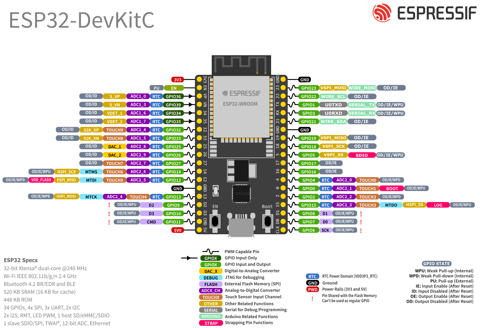
Why GPIO 26? A few ESP32 pins have special jobs, and three groups are worth steering around:
- GPIO 6 to 11 connect to the DevKitC's onboard flash memory, and using them as regular pins will crash your program.
- GPIO 34 to 39 are input-only, so they can listen but can't send a signal, which is what a relay's control wire needs.
- GPIO 0, 2, 5, 12, and 15 are "strapping pins." The chip reads them during startup to decide how to boot, and some of them output brief signals while it does. On a relay, that can mean an unwanted click at power-up.
GPIO 26 isn't in any of those groups. It's also not the GPIO 4 we used for the DHT22 or the GPIO 18 we used for the WS2812B, so all three projects can live on the same board later.
Wiring Table (Recommended: JD-VCC Jumper Removed)
Do this with everything unplugged. First pull the plastic jumper off the VCC / JD-VCC header pins on the relay module. Set it aside rather than throwing it away, in case you want the single-supply arrangement later.
| Relay module pin | Connects to |
|---|---|
| VCC | ESP32 3V3 pin |
| JD-VCC | ESP32 5V pin (shown as 5V or VIN on the DevKitC) |
| GND | ESP32 GND |
| IN1 | ESP32 GPIO 26 |
The 5V pin on the DevKitC passes through the USB cable's 5 V while the board is powered over USB, so the relay coil (about 70 mA) is supplied from your computer's USB port. That's fine for one relay. If you run all four at once, check that your USB port can supply the total.
If your module has no JD-VCC pin (only VCC, GND, and IN), connect VCC to the ESP32's 5V pin instead and watch for the "won't release" symptom described earlier.
Wiring Table: The Load Side
For the load we'll use the 12 V fan, wired through the normally open (NO) contact:
| From | To |
|---|---|
| 12 V supply + | Relay channel 1 COM |
| Relay channel 1 NO | Fan + (red wire) |
| Fan - (black wire) | 12 V supply - |
12 V SUPPLY +
     |
    COM
     |
  [RELAY]
     |
     NO
     |
   FAN +

   FAN -
     |
12 V SUPPLY -
Look at what is not in this table. The 12 V supply's negative side does not connect to the ESP32's ground. That's different from the LED strip tutorial, where the two grounds had to meet. The relay's contacts are completely separate from the control side, so the fan circuit only needs its own loop: out of the supply, through the relay contacts, through the fan, back to the supply. Keeping it that way is also what preserves the isolation we talked about earlier.
That said, the relay module's GND is connected to the ESP32's GND on the control side. That's the logic side only. Don't join the 12 V supply's negative to it.
Add the Flyback Diode Across the Fan
A fan has a motor inside, which is an inductive load, so it makes the same kind of voltage spike as the relay coil when it's switched off. The relay module's flyback diode protects the coil driver. It does nothing for the fan or for the relay's contacts. So we add our own diode right at the fan.
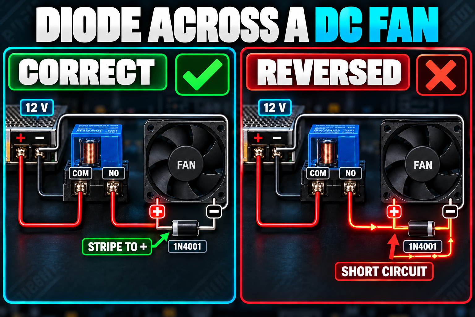
Place the 1N4001 across the fan's two wires, with the striped end (the cathode) connected to the fan's + wire. The diode then sits "backward" against normal current, doing nothing while the fan runs, and giving the spike a path when it stops.
Fan +  ----+---- Diode stripe end (cathode)
           |
          FAN
           |
Fan -  ----+---- Diode plain end (anode)
Put the diode as close to the fan as you can. If you wire it backward, it acts like a short circuit across the fan the moment the relay closes. The fan won't spin, and you can overheat the diode or the supply, so double-check the stripe.
Before You Power Anything
Run through this list with everything unplugged:
- VCC on the relay goes to 3V3, JD-VCC goes to 5V, and no jumper bridges them.
- The fan wiring uses COM and NO, not NC.
- The 12 V supply's negative is not connected to any ESP32 pin.
- The diode's stripe points to the fan's + wire.
- The fan's + wire and the supply's + wire are not swapped.
Then plug in the USB cable first, and the 12 V supply second.
Your First Relay Program
Let's start with the simplest sketch that makes the relay click. It switches the relay on for two seconds and off for two seconds, over and over.
The version below assumes an active-LOW module (LOW turns it on). That's the most common kind.
#define RELAY_PIN 26      // GPIO 26 is wired to the relay module's IN1 pin
#define RELAY_ON  LOW     // an active-LOW module turns ON when the pin is LOW
#define RELAY_OFF HIGH    // and turns OFF when the pin is HIGH

void setup() {
  pinMode(RELAY_PIN, OUTPUT);          // make GPIO 26 an output so it can send a signal
  digitalWrite(RELAY_PIN, RELAY_OFF);  // start with the relay off
}

void loop() {
  digitalWrite(RELAY_PIN, RELAY_ON);   // energize the relay: you should hear a click
  delay(2000);                         // keep it on for 2,000 milliseconds (2 seconds)

  digitalWrite(RELAY_PIN, RELAY_OFF);  // release the relay: a second click
  delay(2000);                         // keep it off for 2 seconds, then loop() repeats
}
Upload it, and you should hear a click, see the module's status LED light up, and watch the fan spin for two seconds. Then another click and the fan stops.
If the behavior is inverted (the fan runs when it should be off), your module is active-HIGH. Swap the two #define lines and upload again. If the relay clicks on but never releases, or buzzes, jump to the 3.3 V section above and the troubleshooting section below.
A couple of things in that sketch deserve explanation.
What Do #define RELAY_ON and #define RELAY_OFF Do?
A #define gives a value a name. When you compile, every RELAY_ON in your code is replaced with LOW.
You could just write digitalWrite(RELAY_PIN, LOW) and digitalWrite(RELAY_PIN, HIGH) everywhere. Now say you later swap to an active-HIGH module. You'd have to hunt through your whole sketch for every LOW and HIGH that means "relay," and be careful not to flip one that controls something else. With the names, you change two lines at the top and nothing else.
Naming also helps anyone reading the code (including you in six months). digitalWrite(RELAY_PIN, RELAY_ON) says exactly what's happening. digitalWrite(RELAY_PIN, LOW) makes the reader work out what LOW means here.
What Happens to the Relay When the ESP32 Starts Up?
The ESP32 doesn't jump straight to your sketch. When it powers on or resets, there's a short period while the chip boots, and during that time your pins aren't doing what your code says yet. They might float (not be driven to any particular voltage) or sit at a default state. Depending on your module, that can cause the relay to click for a fraction of a second at power-up.
For a fan on a desk, that's just a little annoying. For a pump, a heater, a motor, or a machine, an unexpected start could be a real problem.
You can shorten the glitch in software by setting the pin's output level before you switch it to an output:
void setup() {
  digitalWrite(RELAY_PIN, RELAY_OFF);  // load the "off" level first, while the pin is still an input
  pinMode(RELAY_PIN, OUTPUT);          // then make it an output, so it comes up already in the off state
}
On the ESP32 Arduino core, the pin remembers the level you wrote, so when pinMode turns it into an output, it starts out at the safe level instead of at the default. Try it on your own board and module, since the exact behavior depends on the core version and the module's input circuit.
Software only does so much here. Anything that matters, such as a heater, a valve, or a pump, needs a design where the hardware defaults to the safe state, using a pull resistor on the input, the NO or NC choice we talked about, and ideally a separate safety cutout that the ESP32 can't override. Don't rely on code alone.
Is There a Cleaner Way to Handle Active-HIGH and Active-LOW?
Yes. Let's wrap the logic in a function. A function is a named block of code you can run by name, like a command you invent yourself. This one turns the relay on or off no matter which kind of module you have:
#define RELAY_PIN 26                       // GPIO 26 is wired to the relay module's IN pin
const bool RELAY_ACTIVE_LOW = true;        // true = LOW turns the relay on, false = HIGH turns it on

bool relayState = false;                   // remembers whether we think the relay is on (true) or off (false)

void setRelay(bool on) {                   // "on" is true for ON and false for OFF
  relayState = on;                         // store the new state so the rest of the program can check it

  if (RELAY_ACTIVE_LOW) {                  // active-LOW module: the pin level is the opposite of "on"
    digitalWrite(RELAY_PIN, on ? LOW : HIGH);
  } else {                                 // active-HIGH module or driver: the pin level matches "on"
    digitalWrite(RELAY_PIN, on ? HIGH : LOW);
  }
}
The on ? LOW : HIGH part is called the ternary operator. Read it as a one-line question: "Is on true? If so, use LOW; if not, use HIGH."
From here on, the rest of the program simply says setRelay(true) to turn the relay on, and setRelay(false) to turn it off. It never needs to know about HIGH and LOW. If you change modules, you edit one line, RELAY_ACTIVE_LOW, and everything else keeps working. This is the same idea as the #define approach, taken one step further.
Try the First Sketch in the Lab
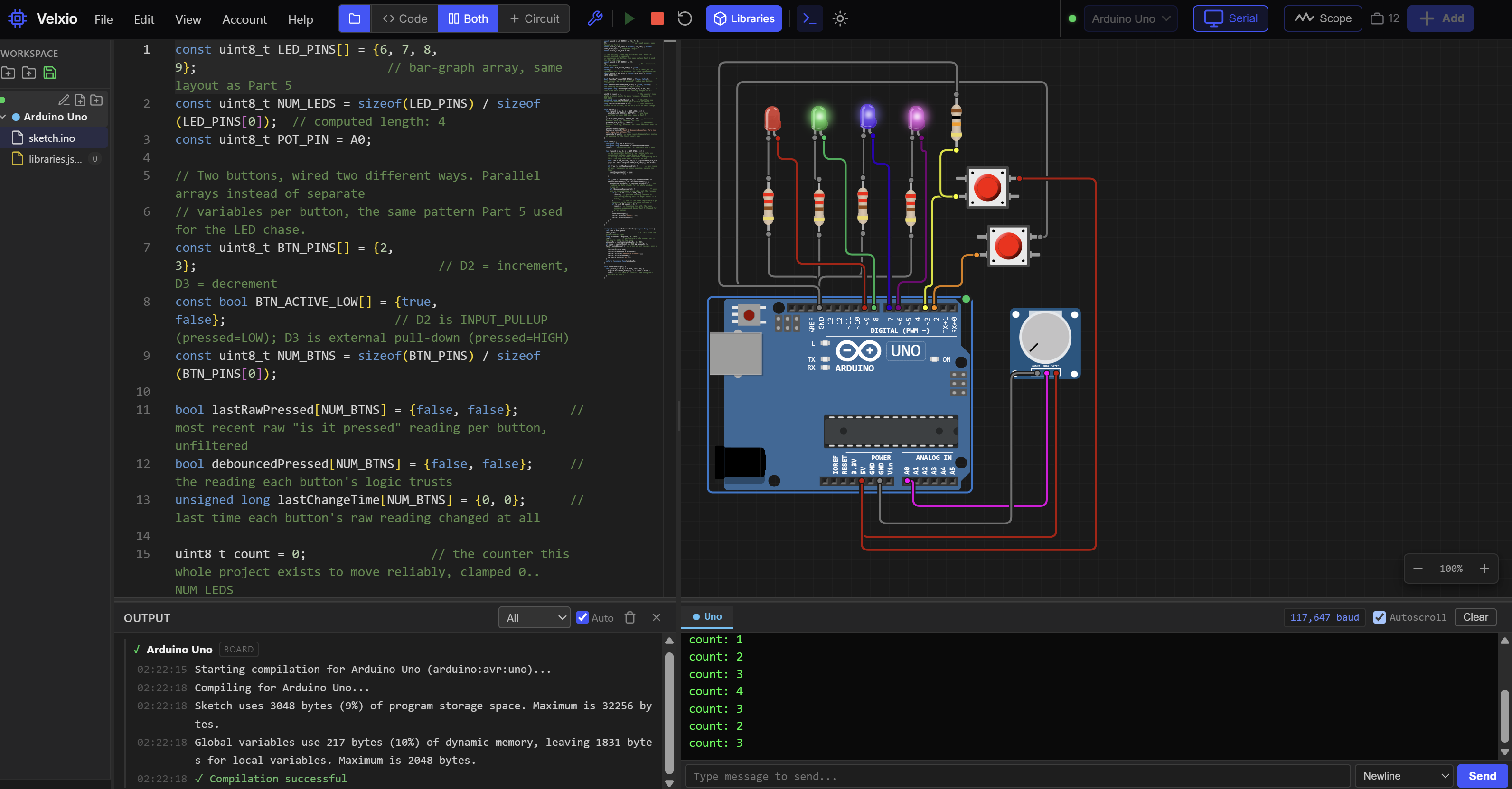
Want to see the circuit run before you wire the real thing, or don't have the parts yet? Run it in The Makers Workbench Electronics Lab.
The Lab doesn't have a finished relay module. It has a bare relay with a coil and contacts instead, which means this is your chance to build the "hard way" version we talked about: the transistor, the resistor, and the diode that a module normally hides from you. Everything you add is a part the Lab provides. You'll need an ESP32, a relay (SPDT), a 2N2222 NPN transistor, a 1 kΩ resistor, a 220 Ω resistor, and an LED.
The relay will switch an LED, since the Lab can show an LED lighting up more clearly than a fan.
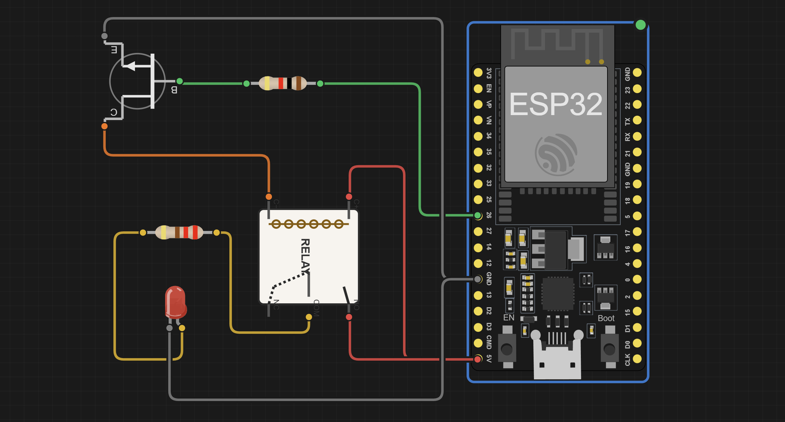
In the Lab, the LED's anode (+) is the right leg and the cathode (-) is the left leg. If the LED stays dark and everything else looks right, check that first.
Leave the relay's flyback diode option switched on in its properties panel. It's the same diode that every real module has.
Here's the key difference from the active-LOW module code. A transistor driver is active-HIGH: a HIGH signal at the base turns the transistor on, which lets current flow through the coil and energizes the relay. So in the sketch, change this one line:
const bool RELAY_ACTIVE_LOW = false; // the transistor driver is active-HIGH, so HIGH turns the relay on
Here is the complete sketch for the Lab. It is the setRelay() version from earlier, with the active-HIGH setting and a loop that switches the relay every two seconds:
#define RELAY_PIN 26                       // GPIO 26 is wired to the transistor driver (through the 1k resistor)
const bool RELAY_ACTIVE_LOW = false;       // the transistor driver is active-HIGH, so HIGH turns the relay on

bool relayState = false;                   // remembers whether we think the relay is on (true) or off (false)

void setRelay(bool on) {                   // "on" is true for ON and false for OFF
  relayState = on;                         // store the new state so the rest of the program can check it

  if (RELAY_ACTIVE_LOW) {                  // active-LOW module: the pin level is the opposite of "on"
    digitalWrite(RELAY_PIN, on ? LOW : HIGH);
  } else {                                 // active-HIGH module or driver: the pin level matches "on"
    digitalWrite(RELAY_PIN, on ? HIGH : LOW);
  }
}

void setup() {
  pinMode(RELAY_PIN, OUTPUT);              // make GPIO 26 an output so it can send a signal
  setRelay(false);                         // start with the relay off
  Serial.begin(115200);                    // start the Serial Monitor connection
}

void loop() {
  setRelay(true);                          // energize the relay: the LED lights
  Serial.println("Relay ON");
  delay(2000);                             // keep it on for 2 seconds

  setRelay(false);                         // release the relay: the LED goes dark
  Serial.println("Relay OFF");
  delay(2000);                             // keep it off for 2 seconds, then loop() repeats
}
Run it. The relay clicks, the LED lights for two seconds and then goes dark for two seconds, and the Serial Monitor prints Relay ON and Relay OFF to match.
The Lab project below has the circuit wired and this sketch loaded, so you can press Run right away.
The Lab circuit is wired like this:
| From | To | Why |
|---|---|---|
| ESP32 GPIO 26 | 1 kΩ resistor, then the transistor's base | The small control signal goes in the base |
| Transistor emitter | GND | The transistor's exit to ground |
| Transistor collector | Relay COIL- | The transistor completes the coil's path to ground |
| Relay COIL+ | ESP32 5V (VIN) | Power for the coil |
| Relay NO | ESP32 5V (VIN) | Power for the switched circuit |
| Relay COM | 220 Ω resistor, then LED anode | The switched output |
| LED cathode | GND | The LED's return path |
(A quick look at the resistor: the transistor's base needs only a few milliamps to switch the coil's larger current. The ESP32's 3.3 V minus the transistor's roughly 0.7 V base-to-emitter drop leaves about 2.6 V across 1 kΩ, which is 2.6 mA. A 2N2222 amplifies that enough to carry the coil's roughly 70 mA with room to spare.)
How Do I Control the Relay from the Serial Monitor?
Now let's make the relay respond to commands instead of a fixed pattern. The Serial Monitor is a window in the Arduino IDE (Tools > Serial Monitor) where your board and your computer can send each other text. Here we'll type ON or OFF and watch the relay follow.
#define RELAY_PIN 26                       // GPIO 26 is wired to the relay module's IN pin
const bool RELAY_ACTIVE_LOW = true;        // true for an active-LOW module, false for active-HIGH

bool relayState = false;                   // tracks whether the relay is currently on

void setRelay(bool on) {                   // turns the relay on (true) or off (false)
  relayState = on;                         // remember the new state

  if (RELAY_ACTIVE_LOW) {                  // pick the right pin level for this kind of module
    digitalWrite(RELAY_PIN, on ? LOW : HIGH);
  } else {
    digitalWrite(RELAY_PIN, on ? HIGH : LOW);
  }

  Serial.print("Relay: ");                 // report what we just did, so we can see it on screen
  Serial.println(on ? "ON" : "OFF");
}

void setup() {
  Serial.begin(115200);                    // open the serial connection at 115200 bits per second

  digitalWrite(RELAY_PIN, RELAY_ACTIVE_LOW ? HIGH : LOW);  // set the "off" level before enabling the output
  pinMode(RELAY_PIN, OUTPUT);              // now make the pin an output
  setRelay(false);                         // make sure we start with the relay off

  Serial.println("ESP32 Relay Controller");
  Serial.println("Type ON or OFF and press Enter");
}

void loop() {
  if (Serial.available()) {                // is there any text waiting from the computer?

    String command = Serial.readStringUntil('\n');   // read one line of text (up to the Enter key)
    command.trim();                        // remove stray spaces and the invisible carriage return

    if (command.equalsIgnoreCase("ON")) {          // matches ON, on, On, and so on
      setRelay(true);
    }
    else if (command.equalsIgnoreCase("OFF")) {    // matches OFF, off, Off, and so on
      setRelay(false);
    }
    else {                                 // anything else is not a command we know
      Serial.println("Unknown command. Type ON or OFF.");
    }
  }
}
Open the Serial Monitor and set the speed in the bottom corner to 115200 baud (baud is the speed of the serial connection, and both sides must agree). If nothing seems to happen when you type, check the dropdown beside it. It should say "Newline" or "Both NL & CR", which tells the Monitor to send the Enter key along with your text. Without that, the sketch waits for a line ending that never arrives.
Type ON, press Enter, and the relay clicks on. Type OFF and it releases. That's the first real step from a canned blinker to something you control on demand.
Why Does delay() Become a Problem?
Suppose you want to run a pump for 30 seconds. The simplest way is:
setRelay(true);    // turn the pump on
delay(30000);      // wait 30,000 milliseconds (30 seconds)
setRelay(false);   // turn the pump off
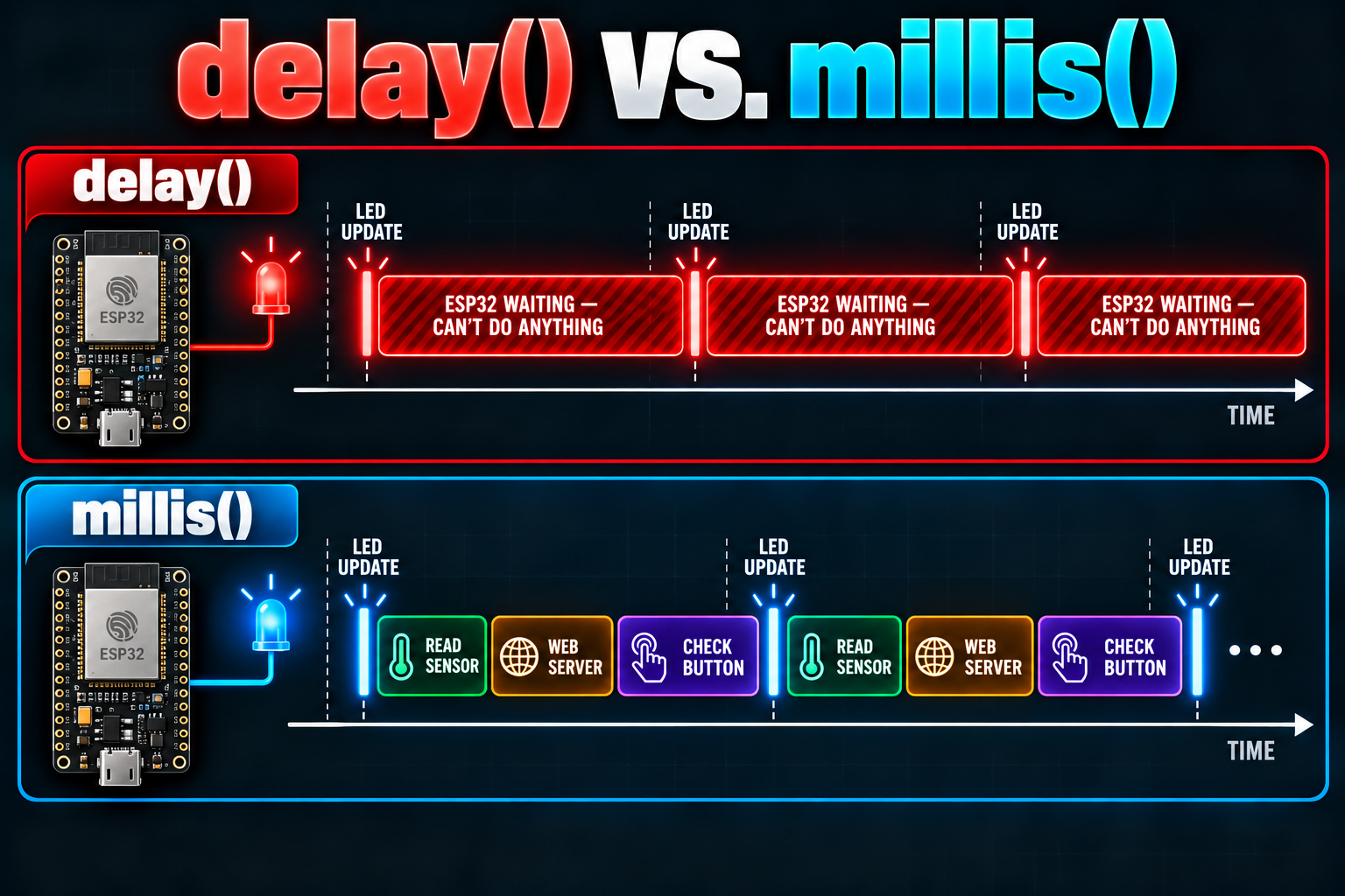
That works. The problem is what the ESP32 is doing for those 30 seconds: nothing. delay() stops everything. It can't read a button, can't notice a water-level sensor reaching the top, can't answer a web page, can't update a display, and can't hear you typing OFF into the Serial Monitor to stop it early. For a pump or heater, being unable to react to a safety condition is a real concern, not just an inconvenience.
We ran into the same problem in the DHT22 and WS2812B tutorials, and the answer is the same one: stop waiting, and start checking the clock.
How Do I Time the Relay Without delay()?
The ESP32 keeps a running count of how many milliseconds have passed since it started. The function that reads it is millis(). Instead of freezing, the program looks at the clock on every pass through loop(), compares it with the time of the last change, and acts only when enough time has passed. In between, the loop keeps spinning and the ESP32 stays free to do other work.
Here's a relay that switches every five seconds without any delay():
#define RELAY_PIN 26                       // GPIO 26 is wired to the relay module's IN pin
const bool RELAY_ACTIVE_LOW = true;        // true for an active-LOW module, false for active-HIGH

bool relayState = false;                   // tracks whether the relay is currently on

unsigned long previousMillis = 0;          // the clock reading when we last switched the relay
const unsigned long interval = 5000;       // how long to wait between switches, in milliseconds

void setRelay(bool on) {                   // turns the relay on (true) or off (false)
  relayState = on;
  if (RELAY_ACTIVE_LOW) {
    digitalWrite(RELAY_PIN, on ? LOW : HIGH);
  } else {
    digitalWrite(RELAY_PIN, on ? HIGH : LOW);
  }
}

void setup() {
  Serial.begin(115200);                    // open the serial connection so we can print status
  digitalWrite(RELAY_PIN, RELAY_ACTIVE_LOW ? HIGH : LOW);  // set the "off" level first
  pinMode(RELAY_PIN, OUTPUT);              // then make the pin an output
  setRelay(false);                         // start with the relay off
}

void loop() {
  unsigned long currentMillis = millis();  // read the clock once per pass

  if (currentMillis - previousMillis >= interval) {   // has 5 seconds passed since the last switch?
    previousMillis = currentMillis;        // yes: remember this moment as the new "last switch"

    setRelay(!relayState);                 // flip the relay: if it was on, turn it off, and if it was off, turn it on

    Serial.print("Relay: ");                // report the change
    Serial.println(relayState ? "ON" : "OFF");
  }

  // Other ESP32 tasks (buttons, sensors, Wi-Fi) can run here, and they are never kept waiting.
}
The subtraction currentMillis - previousMillis is deliberate, rather than comparing two times directly. It keeps working correctly even when the millisecond counter eventually rolls over to zero after about 49 days, which is the same wraparound-safe pattern from the Arduino series.
How Do I Run the Relay for a Set Time After a Command?
The blinking sketch shows the pattern. What you'd use for a pump or a fan is slightly different: a command starts the relay, and the relay switches itself off after a set time. You can also cancel it early. Here it is, built on the same idea:
#define RELAY_PIN 26                       // GPIO 26 is wired to the relay module's IN pin
const bool RELAY_ACTIVE_LOW = true;        // true for an active-LOW module, false for active-HIGH

const unsigned long RUN_TIME = 10000;      // how long the relay stays on after START, in milliseconds
bool relayState = false;                   // is the relay currently on?
bool timerRunning = false;                 // is an automatic shut-off timer currently counting down?
unsigned long startTime = 0;               // the clock reading when the relay was switched on

void setRelay(bool on) {                   // turns the relay on (true) or off (false)
  relayState = on;
  if (RELAY_ACTIVE_LOW) {
    digitalWrite(RELAY_PIN, on ? LOW : HIGH);
  } else {
    digitalWrite(RELAY_PIN, on ? HIGH : LOW);
  }
}

void setup() {
  Serial.begin(115200);                    // open the serial connection
  digitalWrite(RELAY_PIN, RELAY_ACTIVE_LOW ? HIGH : LOW);  // set the "off" level first
  pinMode(RELAY_PIN, OUTPUT);              // then make the pin an output
  setRelay(false);                         // start with the relay off
  Serial.println("Type START to run for 10 seconds, STOP to cancel");
}

void loop() {
  if (Serial.available()) {                // is a command waiting?
    String command = Serial.readStringUntil('\n');   // read one line
    command.trim();                        // clean off spaces and the carriage return

    if (command.equalsIgnoreCase("START")) {
      setRelay(true);                      // turn the relay on now
      startTime = millis();                // note the moment it started
      timerRunning = true;                 // and begin counting down
      Serial.println("Relay ON, will stop in 10 seconds");
    }
    else if (command.equalsIgnoreCase("STOP")) {
      setRelay(false);                     // turn off right away
      timerRunning = false;                // cancel the countdown
      Serial.println("Relay OFF (stopped early)");
    }
  }

  // Has the countdown finished? This check runs on every pass, so it never misses.
  if (timerRunning && (millis() - startTime >= RUN_TIME)) {
    setRelay(false);                       // time is up: turn the relay off
    timerRunning = false;                  // stop counting
    Serial.println("Timer finished, relay OFF");
  }
}
Type START and the relay runs for ten seconds and shuts itself off. Type STOP partway through, and it shuts off right then. Because the program never sits in a delay(), the STOP command is heard immediately, which is the whole reason for the extra work. (One small honest detail: readStringUntil waits up to a second for the end of a line once text starts arriving, but that only happens when you've actually typed something.)
Try the Non-Blocking Timer in the Lab
You can run both timing sketches in the Lab too, using the same transistor-driven relay circuit from the first Lab section.
The Lab project below has the circuit wired and the START / STOP sketch loaded, with RELAY_ACTIVE_LOW already set to false. To try the 5-second toggle sketch instead, paste it into the editor in its place. Press Run and open the Serial Monitor.
The wiring is unchanged:
| From | To | Why |
|---|---|---|
| ESP32 GPIO 26 | 1 kΩ resistor, then the transistor's base | The small control signal goes in the base |
| Transistor emitter | GND | The transistor's exit to ground |
| Transistor collector | Relay COIL- | The transistor completes the coil's path to ground |
| Relay COIL+ | ESP32 5V (VIN) | Power for the coil |
| Relay NO | ESP32 5V (VIN) | Power for the switched circuit |
| Relay COM | 220 Ω resistor, then LED anode | The switched output |
| LED cathode | GND | The LED's return path |
Set RELAY_ACTIVE_LOW to false as before. For the START / STOP sketch, open the Lab's Serial Monitor, type your commands, and watch the LED. The relay should click on, stay on for ten seconds, then click off, and STOP should cut it short.
To send a command, open the Serial Monitor and click the box that says Type message to send.... Type START and press Send. Leave the menu next to the box on Newline: the sketch reads one whole line at a time, so it needs that line ending to know the command is finished. The LED lights, and ten seconds later the Serial Monitor prints Timer finished, relay OFF and the LED goes dark. Send STOP the same way at any time to cut the run short.
How Fast Can a Relay Switch?
A relay is a mechanical device. Something physically moves every time it switches, which takes real time (about 10 milliseconds each way for the relay in this tutorial) and causes real wear.
Two consequences follow from that:
- Don't use a relay for fast switching or PWM dimming. PWM (pulse-width modulation) means switching something on and off very rapidly, hundreds or thousands of times per second, to control how much power it gets, such as dimming an LED or setting a motor's speed. A relay can't keep up, and you'd wear out its contacts in a very short time. Use a MOSFET for that.
- Keep an eye on the number of operations. The datasheet lists a mechanical life in the millions of switches, and a much shorter electrical life (roughly 100,000 operations at full rated load). A relay that switches once a minute at full load uses up its electrical life in about 70 days. A relay that switches a fan a few times a day will outlast you.
Relays shine for ON/OFF control that happens occasionally, such as pumps, fans, lamps, valves, heaters, and appliances.
Because the contacts are physical metal, they also bounce. For a few milliseconds after closing, they can rattle open and shut before settling. A lamp or a fan doesn't care. If you ever use a relay's contacts as a clean digital signal into another circuit, you'll need to account for it.
Do I Need Anything Extra for Motors and Other Inductive Loads?
We added a diode to the fan, and the reason deserves its own note, since people often get this wrong.
The flyback diode on the relay module protects the module's own coil driver. It doesn't protect the relay's contacts from your load. If the load is a motor, solenoid, valve, or another relay coil, switching it off sends a voltage spike back through the contacts, which makes the arcing worse and shortens the contacts' life.
For a DC inductive load, the fix is the same as before: a diode across the load, with the stripe toward the positive side. For an AC inductive load (not something we're doing here), the common fixes are different parts: an RC snubber (a resistor and capacitor in series across the contacts) or a TVS diode (a diode built to soak up voltage spikes in both directions). Whatever protection applies, check the relay and load documentation.
Should I Use a Relay, a MOSFET, or a Solid-State Relay?
A relay isn't always the right choice, and part of understanding relays is knowing when not to reach for one.
Suppose you want to switch a 12 V LED strip. A MOSFET (a transistor designed to switch larger currents) can do it. Compared with a relay it offers:
- No moving parts to wear out
- Silent operation
- Very fast switching and PWM dimming
- A smaller size
- Often lower power loss
A relay's advantages are different:
- It can switch AC or DC, within its ratings
- Its contacts are electrically separate from the control side, so it can switch a circuit that doesn't share the ESP32's ground
- NO/NC wiring is simple and gives you a fail-safe choice
- The switched circuit sees a plain mechanical switch, with no voltage drop or leakage
A solid-state relay (SSR) acts like a relay but uses electronics instead of a moving contact. It's silent, quick, and doesn't wear out the way contacts do, but it has its own tradeoffs. Depending on type, an SSR may only work with AC or only with DC, may leak a small current when "off," may drop a volt or so when "on" and produce heat as a result, and may need a heatsink. A mechanical relay isn't automatically inferior to an SSR, and an SSR isn't automatically better.
| Feature | Relay | MOSFET | Solid-state relay |
|---|---|---|---|
| Moving parts | Yes | No | No |
| Silent | No (clicks) | Yes | Yes |
| Fast switching / PWM | No | Yes | Limited |
| Switches AC | Yes | Not directly | Often (AC types) |
| Switches DC | Yes (lower rating) | Yes | DC types only |
| Control side separate from load | Yes | No (shares ground) | Yes |
| Leaks a little current when off | No | Little | Often |
| Voltage drop when on | Almost none | Small | Often about 1 V |
How Do I Make a Relay React to a Sensor?
Control by timer or command is a good start, but the ESP32 gets much more useful when the relay responds to the world: turn on a fan when it gets hot, turn on a pump when the soil is dry. The simplest version looks like this:
if (temperature >= 80.0) {   // if it's 80 degrees or hotter
  setRelay(true);            // turn the fan on
} else {
  setRelay(false);           // otherwise turn the fan off
}
That works, but it has a nasty flaw, and you'll see it the first time your reading hovers near 80. Real sensors wobble a little:
79.9 80.1 79.8 80.0 79.9 80.2
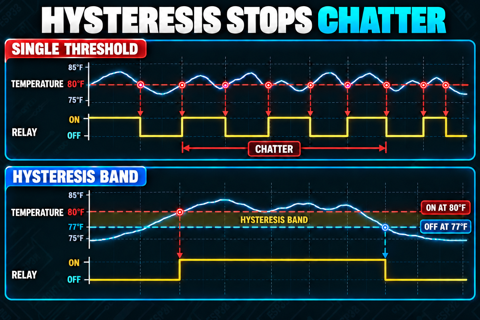
With a single threshold, the relay goes OFF, ON, OFF, ON, OFF, ON as the reading wiggles across the line, maybe several times a second. The relay is clicking away, wearing out its contacts, and your fan is being slammed on and off. This behavior is called chattering.
What Is Hysteresis?
Think of a home thermostat. When it's set to 70 °F in winter, the furnace doesn't flick on at 69.9 and off at 70.0. It turns on when the temperature drops a little below the target, then runs until the house is a little above the target. That gap keeps it from cycling every few seconds.
That gap is called hysteresis, and it means using two thresholds instead of one:
Fan ON  at 80 degrees or above
Fan OFF at 77 degrees or below
Between 77 and 80, the relay keeps doing whatever it was already doing. Once the fan turns on, the temperature must fall all the way to 77 before it turns off again. The three-degree gap absorbs all the wobble.
A Complete Hysteresis Sketch You Can Test Right Now
You don't need a temperature sensor to try this. The sketch below lets you play the part of the sensor: type a temperature into the Serial Monitor and the relay reacts to it with hysteresis. Type 82 and the fan turns on. Type 79 and it stays on (inside the band). Type 76 and it turns off. Type 78 and it stays off.
#define RELAY_PIN 26                       // GPIO 26 is wired to the relay module's IN pin
const bool RELAY_ACTIVE_LOW = true;        // true for an active-LOW module, false for active-HIGH

const float FAN_ON_TEMP  = 80.0;           // turn the fan ON at or above this temperature (degrees F)
const float FAN_OFF_TEMP = 77.0;           // turn the fan OFF at or below this temperature (degrees F)

bool relayState = false;                   // is the fan relay currently on?

void setRelay(bool on) {                   // turns the relay on (true) or off (false)
  relayState = on;
  if (RELAY_ACTIVE_LOW) {
    digitalWrite(RELAY_PIN, on ? LOW : HIGH);
  } else {
    digitalWrite(RELAY_PIN, on ? HIGH : LOW);
  }
}

void setup() {
  Serial.begin(115200);                    // open the serial connection
  digitalWrite(RELAY_PIN, RELAY_ACTIVE_LOW ? HIGH : LOW);  // set the "off" level first
  pinMode(RELAY_PIN, OUTPUT);              // then make the pin an output
  setRelay(false);                         // start with the fan off
  Serial.println("Type a temperature (for example 82) and press Enter");
}

void loop() {
  if (Serial.available()) {                // did a line of text arrive?
    String text = Serial.readStringUntil('\n');   // read the whole line
    text.trim();                           // strip spaces and the carriage return

    if (text.length() > 0) {               // ignore empty lines
      float temperature = text.toFloat();  // turn the text into a number (text that isn't a number reads as 0)

      if (!relayState && temperature >= FAN_ON_TEMP) {        // fan is off AND it got hot enough
        setRelay(true);
        Serial.println("Hot enough: fan ON");
      }
      else if (relayState && temperature <= FAN_OFF_TEMP) {   // fan is on AND it cooled enough
        setRelay(false);
        Serial.println("Cool enough: fan OFF");
      }
      else {                               // inside the band: leave the relay as it is
        Serial.println("No change");
      }
    }
  }
}
Look at the two if conditions. The first only fires when the relay is currently off (!relayState) and the temperature has reached the ON threshold. The second only fires when the relay is currently on and the temperature has fallen to the OFF threshold. The relayState variable is what gives the sketch its memory, and that memory is what makes hysteresis work.
Once you finish the DHT22 tutorial, you can replace the typed number with a real reading from the sensor, and the rest of the sketch stays exactly the same. That's where we're headed in the capstone project.
What Can Go Wrong? Troubleshooting ESP32 Relay Problems
The Relay Doesn't Click and the Module's LED Is Off
The module has no power, or the signal isn't arriving. Check that JD-VCC and VCC are connected as in the wiring table, that GND is shared between the ESP32 and the module, and that the wire from GPIO 26 goes to IN1 (and not to another channel's input).
The LED Lights but the Relay Doesn't Click
The logic side is working but the coil isn't getting enough power. With the jumper removed, that usually means JD-VCC isn't connected to a true 5 V source. The ESP32's 3V3 pin can't drive a 5 V relay coil. Measure JD-VCC with a multimeter if you have one.
The Relay Works Backwards
Your module is active-HIGH and your sketch assumes active-LOW (or the reverse). Change RELAY_ACTIVE_LOW and re-upload.
The Relay Clicks On but Won't Release (or Buzzes) When the Pin Is HIGH
This is the 3.3 V problem described earlier. The module's input is seeing a 3.3 V HIGH as only partly "off." In order of preference:
- Remove the VCC / JD-VCC jumper and power
VCCfrom 3V3, as in the wiring table. - If your module has no such jumper, try releasing the pin instead of driving it HIGH: replace the "off" write with
pinMode(RELAY_PIN, INPUT);and switch the pin back withpinMode(RELAY_PIN, OUTPUT);plus a LOW write for "on." A floating input leaves the optocoupler's LED with no current path, which fully turns it off on many modules. Test this on your module before depending on it. - Buy a module sold specifically as 3.3 V compatible.
The Relay Clicks at Power-Up
That's the startup glitch from earlier. Write the "off" level before calling pinMode, as shown in the sketches. If it still clicks at boot and that matters for your application, you need a hardware fix (such as a pull-up or pull-down resistor on the input), not more code.
The ESP32 Resets or Acts Strangely When the Relay Switches
When the coil turns on or off, it can cause a brief dip or spike on the 5 V line, which can reset the ESP32 or make it drop its Wi-Fi connection. Try a better USB cable or a stronger USB port, keep the relay wires away from the ESP32's antenna and signal wires, and double-check that the load's current isn't flowing through any ESP32 pin or ground wire. On a more permanent build, giving the relay coil its own 5 V supply (with grounds joined) usually cures it.
The Fan Runs Even When the Relay Should Be Off
Check which terminal the fan connects to. If you used NC instead of NO, the fan runs when the relay is idle and stops when it's energized. Also confirm your module's active-HIGH/active-LOW setting matches your code.
It Works on the Bench but the Real Load Burns the Contacts or Fails
Compare the load's startup current with the relay's contact rating. Motors, pumps, and lamps pull far more current for the first moment than they do when running, and DC is harder on contacts than AC. Pick a relay with generous headroom, add a diode across DC inductive loads, and check the datasheet.
Board Not Listed Under Tools > Port, or the Upload Hangs
Almost always the USB cable: swap it for one that carries data, not just power. If the upload hangs at "Connecting...", hold the BOOT button on the DevKitC until the upload begins.
Relay Safety Checklist
Before you power up any relay project, go through this list.
- The load is a low-voltage DC load for learning. No mains wiring.
- The load's running and startup current are both well under the contact rating, with margin.
- The load's supply voltage is under the relay's DC contact rating (30 V for the relay in this tutorial).
- The load is wired to COM and NO (or COM and NC, on purpose), and I know what happens if the controller fails.
- A flyback diode is across any motor, solenoid, or coil load, with its stripe toward the + side.
- The load's power supply is separate, and its negative is not tied to an ESP32 pin.
- The relay's coil supply is a proper 5 V source, not 3.3 V.
- The code writes the safe "off" level at startup.
- Nothing dangerous (a heater, a pump with no cutoff) depends on code alone to stay safe.
- I've wired everything with the power unplugged.
What Can You Build with an ESP32 and a Relay?
Once you can switch a relay reliably, the ESP32 can control real things:
- Temperature-controlled fans
- Greenhouse ventilation
- Humidity-controlled equipment
- Irrigation systems and pumps
- Solenoid valves
- Lighting automation
- Timed equipment controllers
- Workshop automation
- Battery chargers
- Alarm outputs
- Remote switches
- Web-controlled devices
- Wi-Fi automation nodes
Combine the relay with sensors and networking, and the ESP32 can make decisions on its own instead of waiting for you to press a button.
Taking This Project Further
We've now built three important pieces of our ESP32 tutorial foundation.
With the AM2302/DHT22, we learned how to collect environmental data and calculate extra measurements such as heat index and dew point.
With the WS2812B, we learned how to turn numbers into a physical visual display.
And with a relay module, we've learned how the ESP32 can act on information by switching an external load.
These can eventually work together:
             AM2302 / DHT22
                    |
                    v
             Temperature
             Humidity
                    |
          +---------+---------+
          |                   |
          v                   v
      WS2812B              ESP32
    Visual Gauge           Logic
                              |
                              v
                            Relay
                              |
                              v
                             Fan
The sensor measures the environment. The LED strip displays it. The ESP32 evaluates it. And the relay lets the system do something about it.
We can also expose the same system over Wi-Fi so a browser can display current measurements and system status. That takes us from a collection of separate components to a complete embedded control system.
Conclusion
A relay module gives an ESP32 the ability to control circuits that a GPIO pin could never drive on its own.
The Arduino code is short: set a pin to an output and change its state. Understanding the hardware around that code is what matters. You now know the difference between a relay's coil and its contacts, what COM, NO, and NC do, how to check whether a module will behave with 3.3 V logic, what active-HIGH and active-LOW mean, what the flyback diode, optocoupler, and JD-VCC jumper are for, and why a contact rating on the case is only the beginning of picking a relay for a real load.
You also know that a relay is a mechanical switch. For fast switching, PWM, silent operation, or extremely high cycle counts, a MOSFET or solid-state relay is a better fit. For straightforward ON/OFF control, relays remain hard to beat.
More importantly, you have another building block for larger projects. Instead of only measuring temperature or displaying a reading, your ESP32 can now use that information to run real hardware.
In an upcoming project, we'll combine all of these pieces into a complete environmental monitoring and control system with temperature and humidity sensing, calculated heat index and dew point, an addressable LED temperature gauge, a browser-based dashboard, and automatic relay control.