How Electrical Ground Works: Mastering Fundamental Electronics Part 10
Draw a battery, a resistor, and an LED in a closed loop. The circuit works on a table, in a car, or inside a spacecraft even when neither battery terminal touches the soil. Yet a schematic may still place a ground symbol beside the battery's negative terminal. In that drawing, the symbol marks the point the designer chose as the voltage reference. In another drawing, a ground symbol may identify a metal enclosure, and in safety work the word may mean protective earth. These meanings can be related, but they are separate things.
The overlap in the word causes real problems. A beginner can assume that anything labeled ground is at zero volts, that connecting a wire to ground makes a circuit safe, or that two grounds on a schematic are the same physical point. None of these is reliably true. A voltage reading depends on where the meter's reference probe is placed, a protective conductor only helps if it is connected and rated correctly, and the voltage between two points both called ground can be small but not zero.
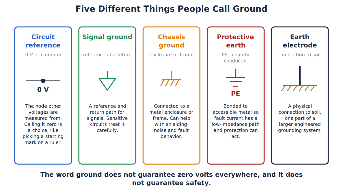
This article separates circuit common, signal ground, chassis, protective earth, and an earth electrode. The word ground does not guarantee zero volts everywhere, and it does not guarantee safety. It also covers how a floating battery circuit works without any earth connection, what ground faults and ground loops are, and how test equipment can create an unintended ground connection.
The article also covers the practical side: joining the grounds of separate supplies and modules, how shared return wiring disturbs sensitive signals, and how static discharge is controlled. It builds on the earlier articles on voltage and on the closed circuit paths described by Kirchhoff's laws. Line power is described only in general terms, and nothing here is a guide to wiring or testing building circuits.
Several Meanings of Ground
A circuit reference, often labeled 0V or common, is the node from which other circuit voltages are measured. Calling it zero does not mean the node has no electrical effect. It only sets the starting mark from which the other voltages are measured.
Signal ground is a reference and return path intended for signals. A sensitive analog circuit may treat it carefully because small unwanted voltage drops can corrupt measurements.
Chassis ground connects to a conductive enclosure or structural frame. It can help control shielding, noise, and fault behavior, depending on the equipment design.
Protective earth is a safety conductor that bonds (deliberately connects) accessible conductive parts to the supply grounding system. Its job is to provide a low-impedance path, one that opposes current very little, for fault current so protective devices can operate. Normal load current should not depend on protective earth in correctly designed equipment.
An earth electrode is a physical connection to soil that forms one part of a larger grounding system. The earth does not act like a bottomless drain that absorbs unwanted electricity. Soil has impedance (opposition to current, much like resistance), and safety depends on the complete engineered fault path and protective system.
Circuit Reference and Return Paths
Voltage is always measured between two points. A 5V rail means one point is 5V relative to a chosen reference. Choose a different reference and the numerical labels change, while the physical differences between nodes remain the same.
Think of elevation on a map. A town may define a local benchmark and call it zero. A hill 100 feet above that mark does not care whether the benchmark is sea level or a survey marker. Circuit ground serves the same bookkeeping role when it is a reference node.
A return path is where current comes back to its source. The return and the reference are often the same conductor in a simple circuit, which encourages people to use the words interchangeably. In larger circuits, current flowing through a real wire or trace creates a small voltage drop. Two points both labeled ground can therefore differ slightly in voltage.
How Kirchhoff’s Circuit Laws Work explains why a closed path is required and why voltage changes around a loop balance. How Direct Current (DC) Works shows the same source-load-return model in a battery circuit.
An Isolated Battery Circuit
Take a 9V battery, a resistor, and an LED connected in a complete loop. Leave the circuit completely disconnected from earth. The LED still lights because charge has a path from one battery terminal, through the load, and back to the other terminal.
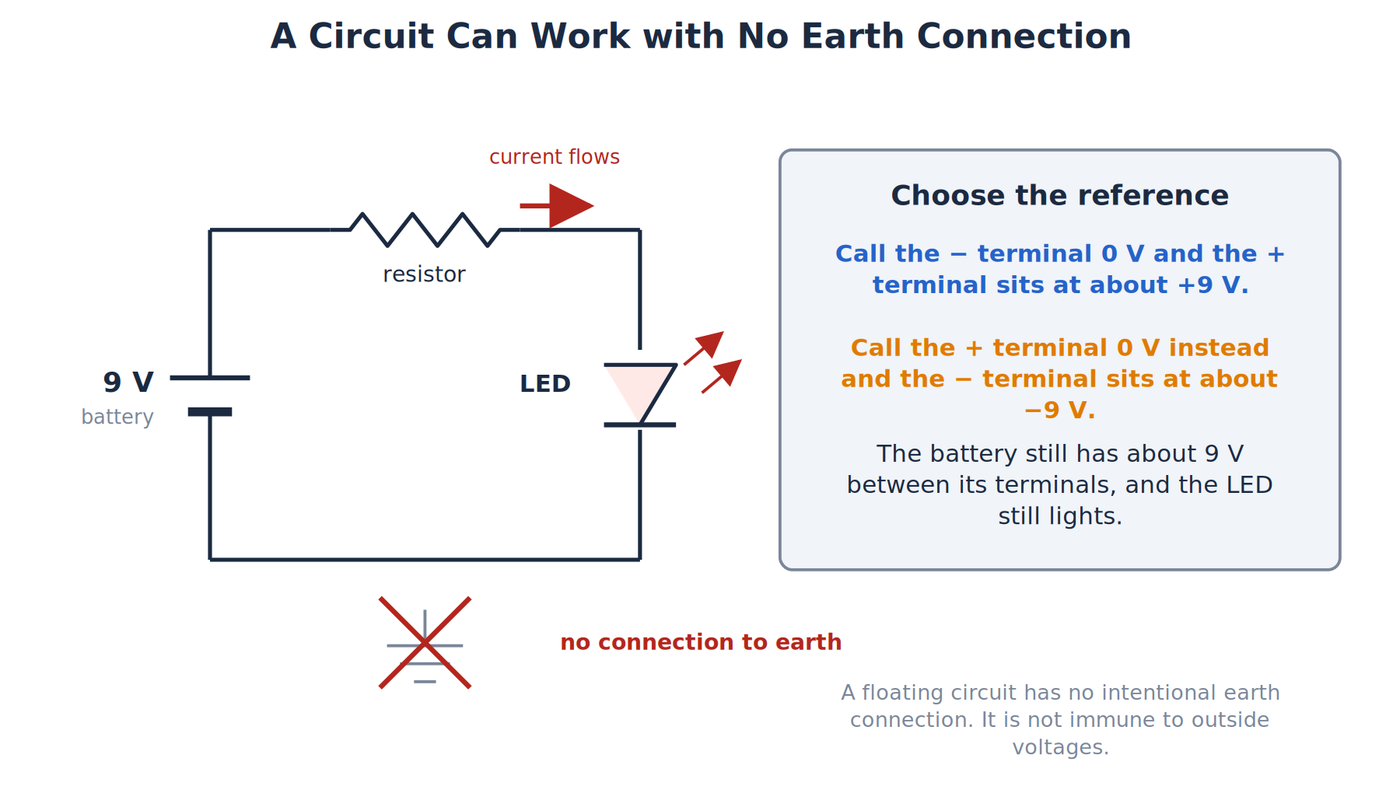
If we call the negative terminal 0V, the positive terminal is about +9V relative to it. We could instead call the positive terminal 0V, in which case the negative terminal is about −9V. The battery still has about 9V between its terminals.
This circuit is floating, meaning neither side is intentionally tied to earth. Floating does not mean immune to every external voltage or hazard. Capacitance, leakage, test instruments, or a person touching it can create a reference. It only describes the lack of an intentional conductive earth connection.
In summary, the reference sets where voltage measurements start, the return path completes the circuit, and a circuit can work with no connection to earth. The remaining sections cover the cases where a connection to earth does matter, which are mostly about safety.
Chassis and Protective Earth
A metal enclosure can become dangerous if a damaged energized conductor touches it. Protective earth is intended to hold accessible metal near the grounding-system potential and carry enough fault current for a fuse, breaker, or other protective device to disconnect the fault.
The important phrase is “low-impedance fault-current path.” A path with too much impedance may not let enough current flow for protection to operate promptly. Protective grounding is therefore an engineered safety function, and the symbol on a schematic stands for a conductor that has to be sized and connected correctly.
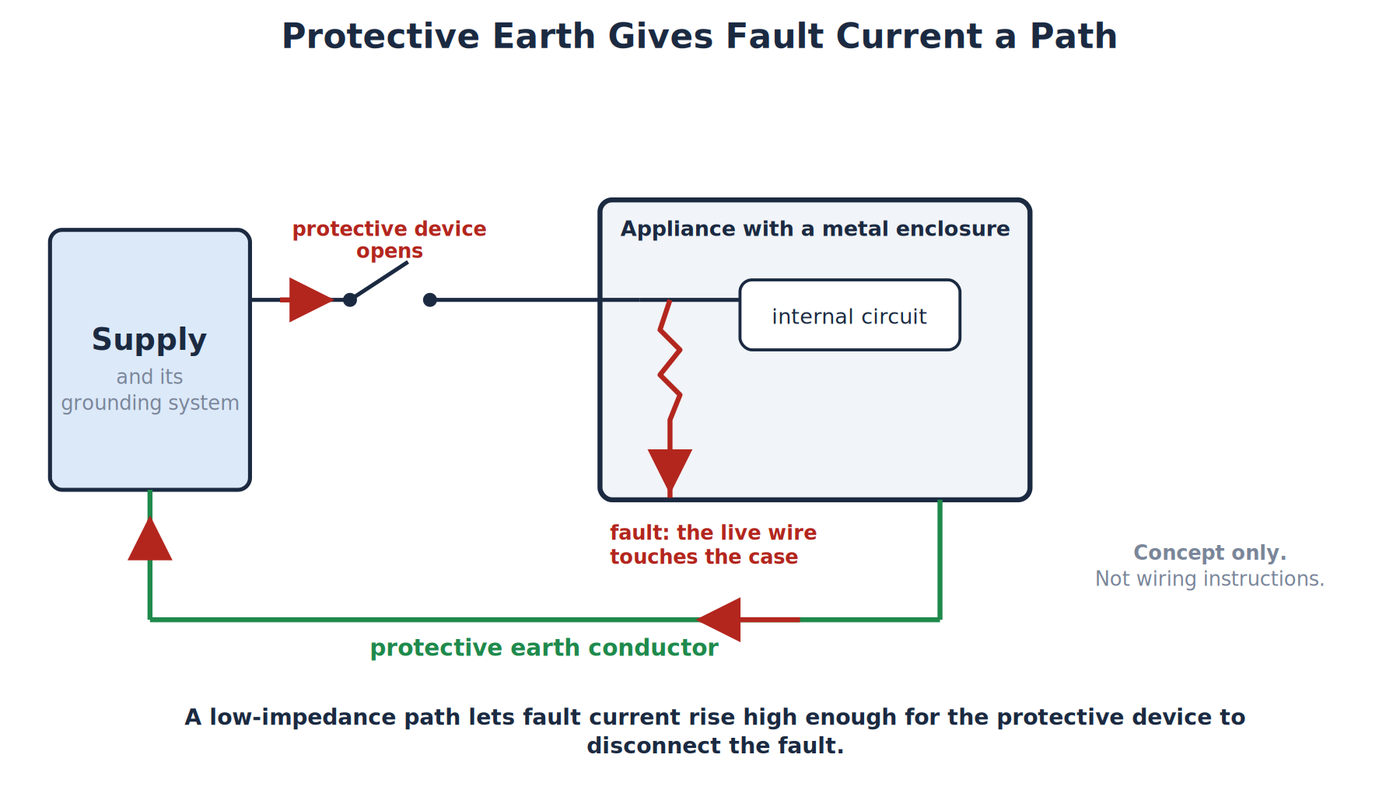
Chassis and protective earth are often bonded in line-powered equipment, but not in every product or at every point. Double-insulated equipment may use other safety methods. Exact requirements vary by jurisdiction and product class, so this article does not provide premises-wiring instructions.
Never remove or defeat a protective-earth pin to cure hum. Doing so leaves a shock hazard in place of the noise problem. Use methods that keep the protective conductor intact, and get qualified help.
Ground Faults and Protection
A ground fault is an unintended conductive connection between an energized conductor and grounded metal or another grounded path. Protective systems aim to detect or clear that condition before accessible parts remain hazardous.
Different devices respond in different ways. Overcurrent protection reacts when fault current becomes high enough. Ground-fault protection (a GFCI in the US) compares currents in the intended conductors and disconnects when an imbalance indicates current is taking another path. The names, thresholds, and rules vary, so do not use this overview to modify building wiring.
Normal load current should return through its intended circuit conductors, not through protective earth. Earth is also not a substitute for a proper circuit return.
Multiple Grounds, Loops, and Measurement
When two pieces of equipment are connected by more than one return or shielding path, the paths can form a loop. A ground loop is a closed conductive route that allows unwanted current to circulate. Small voltage differences and magnetic fields can then introduce hum or measurement error.
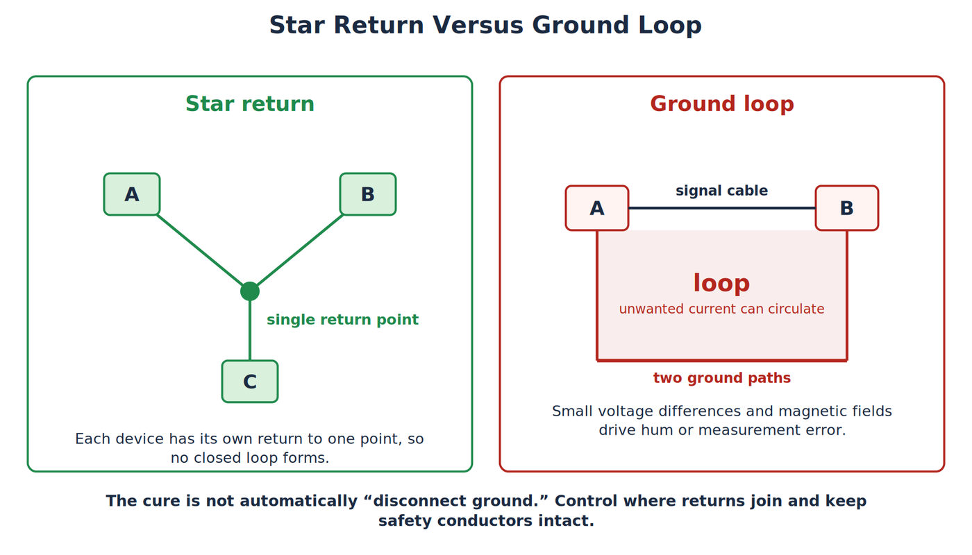
Disconnecting a ground is rarely the right cure. In audio and instrumentation systems, designers may manage shield connections, use differential inputs, control where returns join, or add galvanic isolation. Galvanic isolation means there is no direct conductive path for current between two circuit sections. Every remedy has bandwidth, voltage, safety, and regulatory limits.
Measurement equipment can create a connection you did not intend. Many bench oscilloscope probe ground clips are bonded to protective earth through the power cord. Clipping one to a floating node may force that node to earth potential and create a short circuit. Verify the specific instrument and source before connecting it. A differential probe (one that measures the difference between two points instead of using a ground clip) or an isolated instrument still has maximum voltage and common-mode ratings, which limit the voltage both inputs may share relative to the instrument.
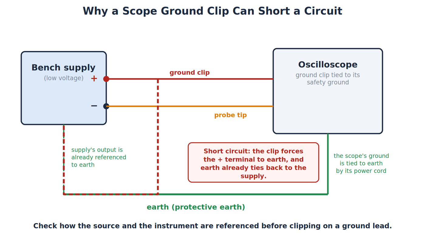
Probing household line circuits is outside this lesson and is not a beginner measurement exercise.
Joining Grounds in a Project
Most projects have more than one power source or board. A microcontroller might run from a USB port while a motor driver runs from a separate 12V supply, or a sensor module might have its own regulator. A signal passing between two such parts is a voltage measured against the sender's ground. The receiver can only interpret it correctly if its own reference is the same point, so the grounds of the two sections must be connected.
Without a shared ground the receiver's input floats relative to the sender, and the result is unreliable readings, signals that seem to work only while a hand touches the boards, or no communication at all. The fix is a wire between the two ground terminals, which gives both sections the same 0V reference.
Join grounds only, and only between extra-low-voltage DC sections. The positive outputs of two supplies should not be connected together, and neither should the grounds of equipment connected to line power unless the design intends it. When a section is powered from the AC line, an isolated supply or an isolating interface (such as an optoisolator, a part that passes a signal across a gap using light) keeps the two sides separate.
On a breadboard, the long strips along the edges are called power rails. Connect the ground rail of each supply to the same rail or to each other, and check whether the board's rails are split in the middle, because some long boards break the rail into two halves that need a jumper.
Shared Return Currents
Every wire has a small resistance, so any current through a ground wire creates a voltage along it. If a motor and a sensor share one return wire, the motor's current surge shifts the sensor's reference.
Suppose a motor draws 2A through a 0.05Ω length of shared ground wire. The voltage along that wire is V = IR = 2A × 0.05Ω = 0.1V. A sensor whose ground connects at the far end of that wire sees every signal shifted by 0.1V while the motor runs. On a 10-bit analog input with a 5V reference, one count is about 4.9mV, so a 0.1V shift is roughly 20 counts of error.
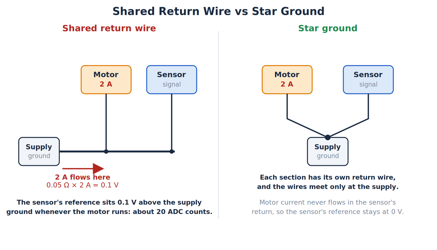
The usual remedy is a star ground, a layout where each section has its own return wire and all returns meet at a single point, normally at the supply. The motor's large current then flows only in its own return wire, and the sensor's reference is taken at the junction. On printed circuit boards, designers use a large continuous copper area called a ground plane, which has so little resistance that return currents cause far smaller voltage shifts.
Static Electricity and ESD
Static charge builds up on people and materials through friction, and it discharges when two objects at different voltages touch. This is electrostatic discharge, abbreviated ESD. A person can feel a static spark only above roughly 3,000V, while many integrated circuits can be damaged by far less. A part can be harmed without any visible sign and then fail later.
Grounding is the main defense. A grounded work surface and a wrist strap bring the person and the parts to the same potential, so charge drains away slowly instead of in a spark. A wrist strap contains a resistor, typically 1MΩ, in series with its cord. That resistor limits the current if the strap touches something energized, and it keeps the strap safe to wear. Never use a strap while working on line-powered equipment.
Without a strap, touch a bare grounded metal object, such as the metal chassis of a plugged-in computer case, before picking up sensitive parts. Keep parts in their anti-static bags until installation, and handle boards by their edges.
Symbols and Safe Practice
Schematics use different symbols for protective earth, chassis, and signal common because their functions differ. A protective-earth symbol should not be swapped casually with a circuit-common symbol.
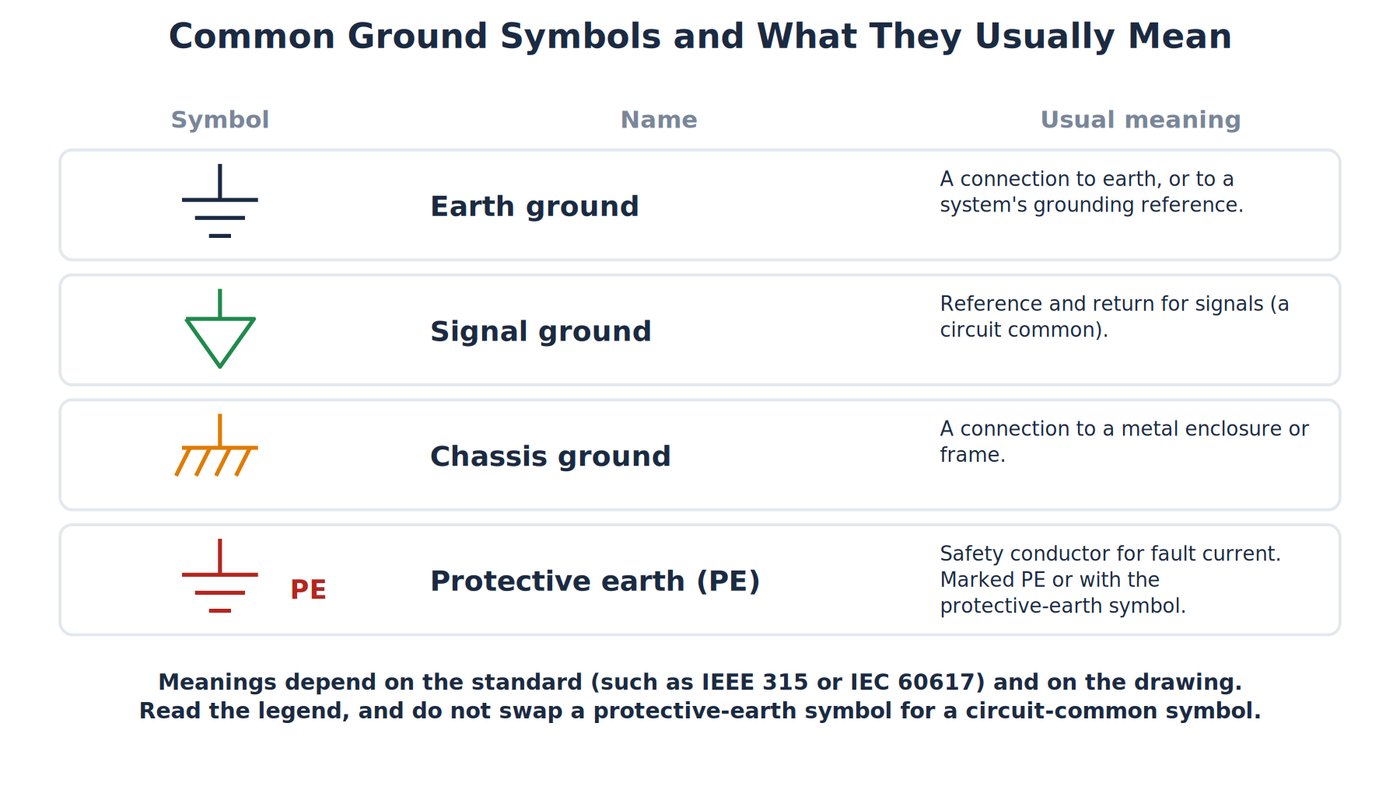
For low-voltage bench work:
- Identify the chosen 0V reference before measuring.
- Trace the intended current return instead of assuming every ground symbol is one perfect node.
- Check whether instruments share protective earth through USB or power cords.
- Keep protective conductors intact.
- Confirm voltage, common-mode, and measurement category ratings (the safety class a meter is built for) before using a probe.
- Stop when the grounding arrangement is uncertain.
A Short History of Grounding
Grounding began with lightning. In the 1750s Benjamin Franklin proposed the lightning rod, a pointed metal conductor on a building connected by a wire to the earth. A strike would then follow the conductor to ground and not pass through the structure. Rods of this kind spread quickly through Europe and North America, and they gave grounding its first purpose: giving a dangerous charge a safe path to earth.
Telegraphy gave grounding a second purpose. In 1838 the German scientist Carl August von Steinheil found that the earth itself could serve as the return path of a telegraph circuit, so a line needed only one wire between stations. This halved the amount of conductor needed over long distances, and many telegraph systems used earth return for decades. It is one reason the same word came to mean a circuit's return path as well as a connection to soil.
Electric power systems added a third purpose. As line-powered equipment became common, a fault inside a device could put dangerous voltage on its metal case, so wiring rules added a protective conductor bonded to the case and to earth. Power utilities also connect part of the system to earth to hold voltages at a known level and to help protective devices trip. In the early 1960s the American engineer Charles Dalziel developed the ground-fault circuit interrupter, which compares the current leaving and returning in a circuit and cuts power when they differ.
Lightning protection, signal return, and fault protection overlap in modern systems, but they remain different engineering jobs. The shared name is a historical accident, and it explains why one word covers several meanings.
Common Misconceptions
- “Ground is always zero volts.” It is a chosen reference, and real conductors can have voltage differences.
- “Ground, neutral, and negative mean the same thing.” Neutral is a return conductor in line-power wiring. These words describe different roles and may or may not connect in a specific system.
- “A floating circuit cannot work.” The isolated battery loop works because it has a complete local return path.
- “Earth absorbs extra electricity.” Protection depends on a complete low-impedance fault path and operating protective devices.
- “A continuity beep proves a safe ground.” It does not establish conductor capacity, impedance under fault conditions, connection quality, or code compliance.
- “Removing earth fixes hum.” Defeating protective earth can create a lethal hazard.
Related Articles
- How Kirchhoff’s Circuit Laws Work explains closed loops and reference nodes.
- How Direct Current (DC) Works follows current through a source, load, and return path.
Wrapping Up
Ground is a role, not one universal substance or node. Circuit common supplies a voltage reference, signal ground supports signals, chassis refers to an enclosure, protective earth supports fault protection, and an earth electrode connects a grounding system to soil. A floating battery circuit proves that earth is not required for every circuit to operate. Treat grounding as part of the whole system, keep protective conductors intact, and verify how test equipment is referenced before connecting a probe. The complete-loop idea behind the return path is covered fully in How Open and Closed Circuits Work, the next article in the series.
Hack The World and Make Awesome.