How Electrical Power Works: Mastering Fundamental Electronics Part 08
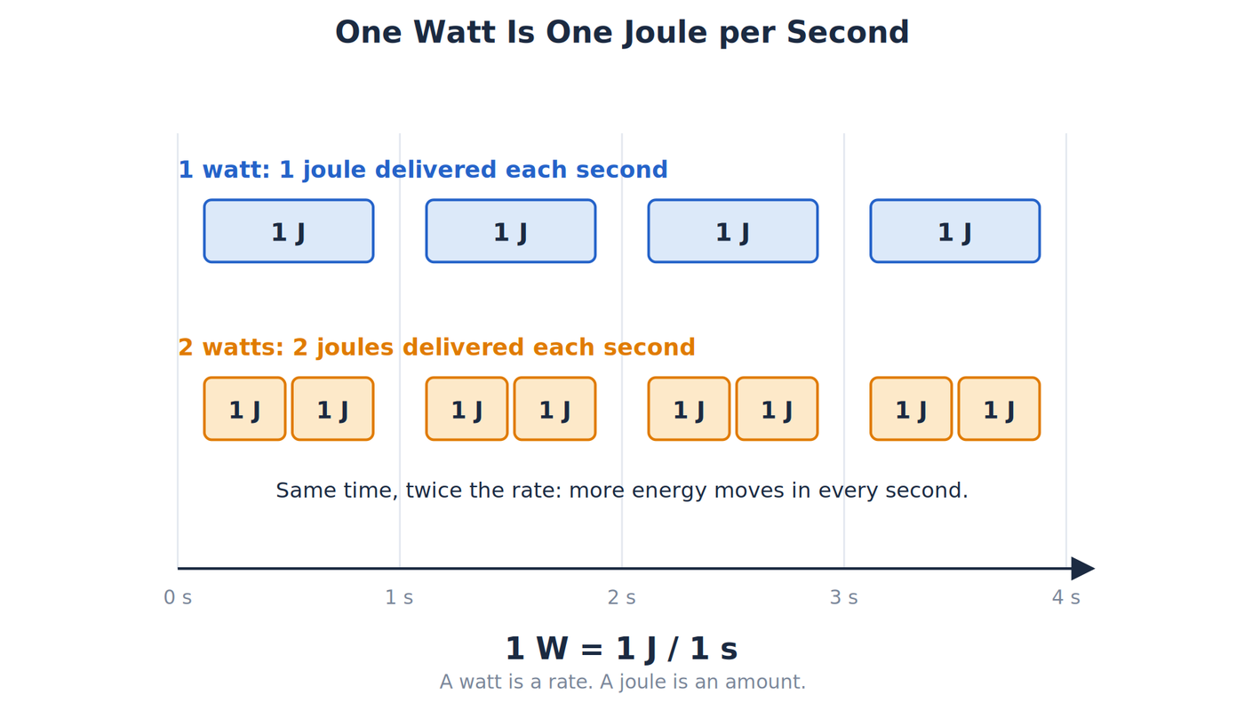
Two pumps can move the same amount of water, but the one that does it in half the time works at twice the rate. Electrical power is that kind of rate. It tells us how quickly electrical energy is being transferred or converted, and it says nothing about how much energy has accumulated.
The unit of power is the watt (W). One watt means one joule of energy transferred each second, where a joule is the basic unit of energy. A 10W circuit transfers energy twice as quickly as a 5W circuit while each is operating. Time determines how much total energy each eventually transfers, which is the subject of How Electrical Energy Works.
Power matters in nearly every practical decision about a circuit. It determines how hot a resistor gets, how large a supply a project needs, and whether a wire or connector can carry a load without overheating. A resistor marked 0.25W and a power supply marked 5V, 2A both make statements about power, and reading those labels correctly requires knowing what the watt measures and how voltage and current produce it.
This article covers power as a rate, the relationship P = VI, and the two resistor forms that follow from Ohm's law. It works through an LED resistor example, explains why a component can either absorb or supply power, and covers ratings and efficiency. It also covers power in series and parallel circuits, average power on AC and pulsed signals, the maximum power a source can deliver, and how to choose a resistor's power rating. The last sections look at the heat in a linear regulator, how to plan a power budget for a small project, and how to measure power and check a calculation at low voltage. It assumes the earlier articles on voltage, current, and Ohm's law.
Power Is a Rate
In symbols, power is energy divided by time:
P = dE/dt
That notation is calculus shorthand for energy change per instant of time, and you can safely read it as "energy divided by time." For a steady rate, the idea becomes P = E/t. Power can change from instant to instant, so engineers distinguish instantaneous power, the value at one moment, from average power, the average over an interval.
Electrical circuits give us a direct way to find that rate:
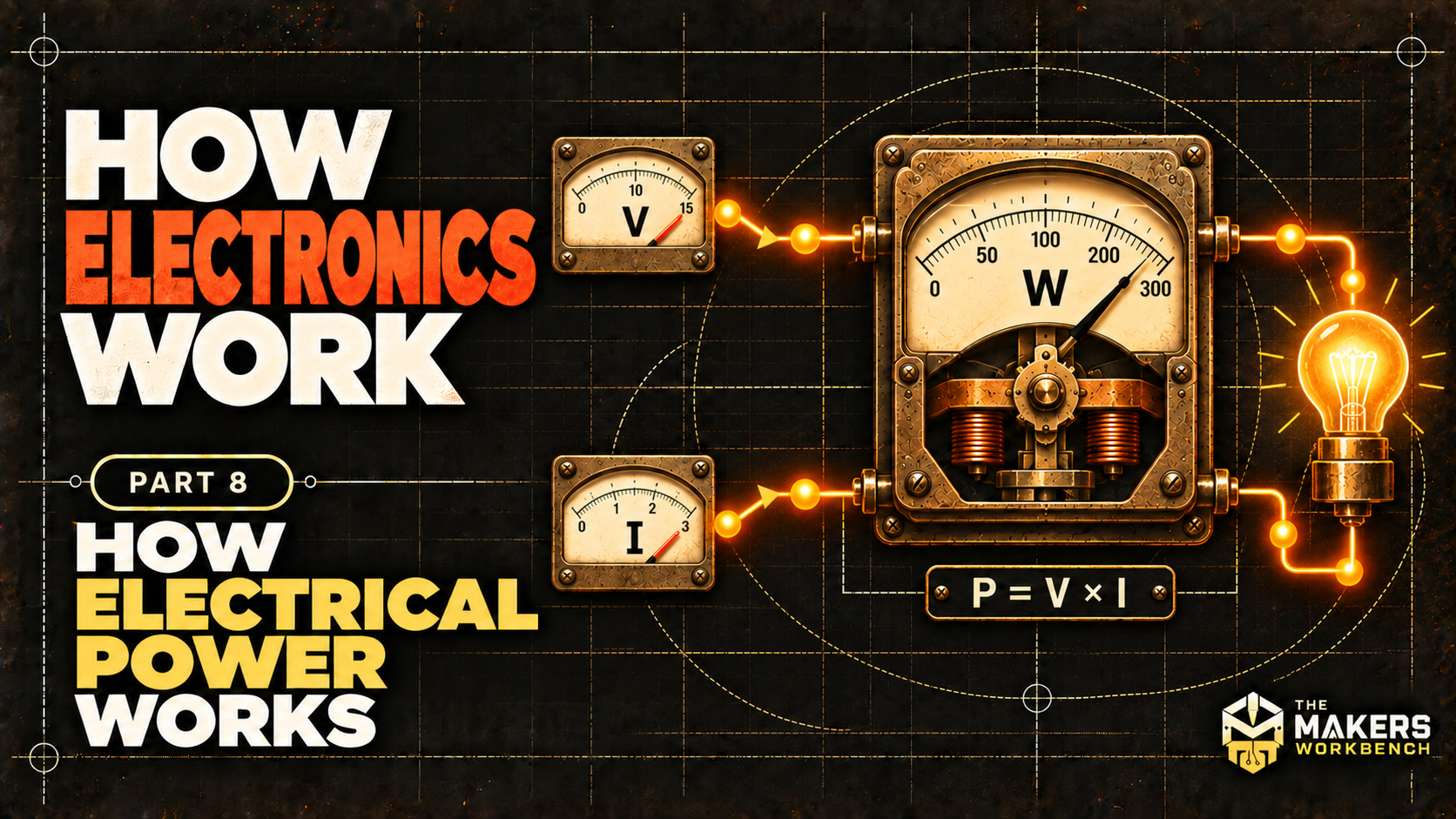
P = V × I
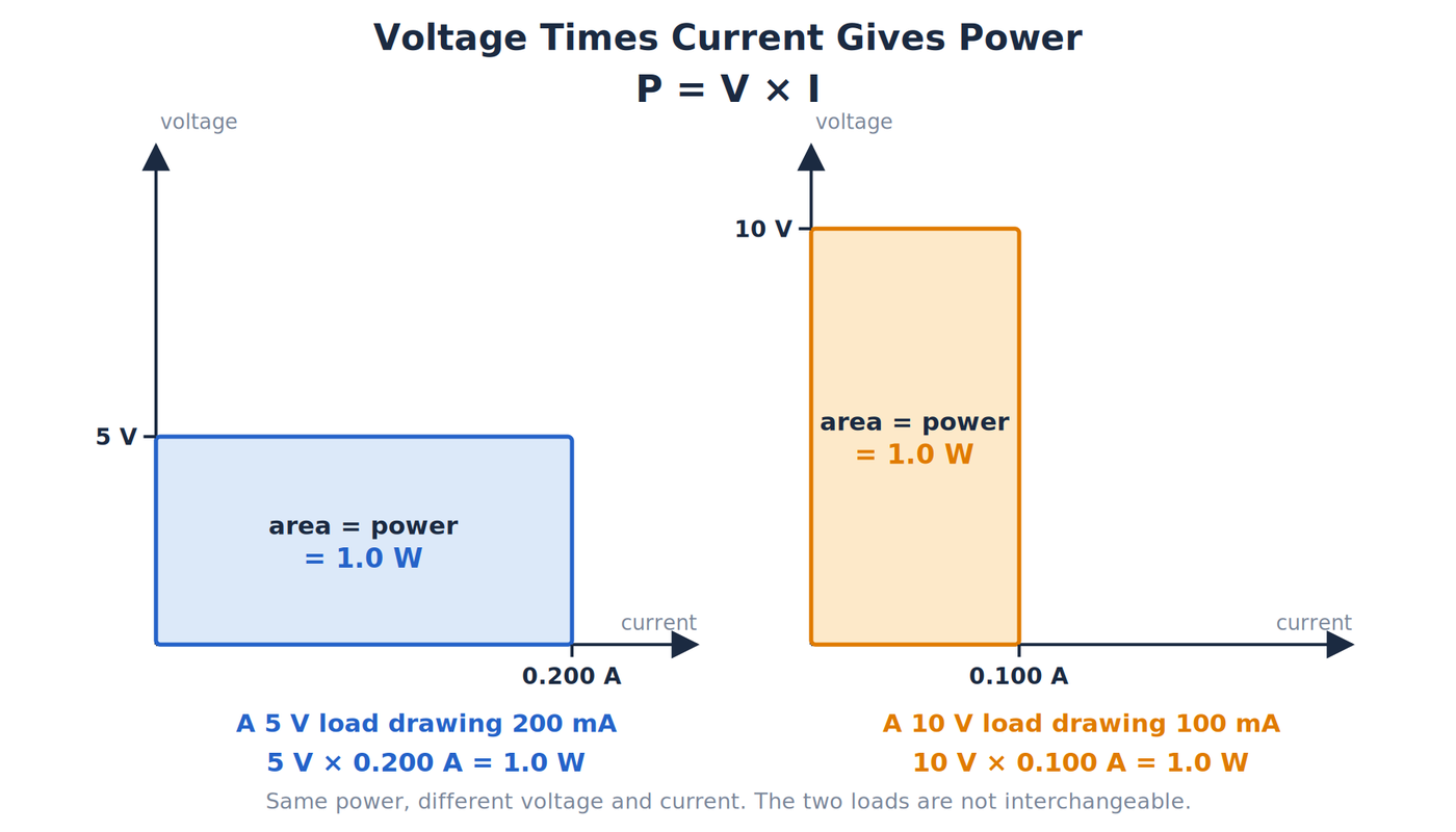
Voltage, V, is energy per unit charge. Current, I, is charge passing per second. Multiply energy per charge by charge per second and the charge units cancel, leaving energy per second. That is power.
A 5V load drawing 200mA uses:
P = 5V × 0.200A = 1.0W
Remember to convert milliamps to amps before calculating. A 10V load drawing 100mA also receives 1W, but those loads are not interchangeable. Their required voltages and currents differ even though their powers match.
Prefixes and Other Power Units
Electronics spans a huge range of power levels, so the watt is usually written with a prefix.
| Prefix | Symbol | Value | Example |
|---|---|---|---|
| microwatt | µW | 0.000001W | A sleeping low-power sensor |
| milliwatt | mW | 0.001W | A small indicator LED |
| watt | W | 1W | A microcontroller board with sensors |
| kilowatt | kW | 1,000W | A space heater uses about 1.5kW |
| megawatt | MW | 1,000,000W | A large power plant unit |
Two older units still appear on labels. Mechanical horsepower equals about 746W, so a 1 hp motor can draw roughly that much electrical power at its output shaft before losses. Heating and cooling equipment is often rated in BTU per hour, and 1W equals about 3.41 BTU per hour. All of these measure the same quantity, power, in different units.
Resistor Power and Heat
A resistor converts electrical energy mostly into thermal energy. If you know voltage and current, P = VI always gives the power at that operating point. For an ohmic resistor (one whose current rises in direct proportion to voltage), How Ohm’s Law Works gives V = IR. Substitution produces two additional forms:
P = I²R
P = V²/R
Use I²R when current is known and V²/R when voltage is known. These forms assume a resistor whose resistance is meaningful at that operating point. Do not treat a nonlinear LED, motor, or processor as a fixed resistor just to force it into V²/R.
The two forms respond to resistance in opposite ways. If current is held constant, increasing resistance increases power because P = I²R. If voltage is held constant, increasing resistance decreases power because P = V²/R. The statement “more resistance means more heat” is incomplete until it says which quantity stays fixed.
Power in Series and Parallel Circuits
The total power a circuit uses is the sum of the power in each part, so it can be found by adding the individual values or by multiplying the source voltage by the source current. How the power divides among the parts depends on whether they are in series or in parallel.
Take a 12V source and two resistors, R1 = 100Ω and R2 = 200Ω. In series, the same current flows through both:
I = 12V / (100Ω + 200Ω) = 0.040A
P1 = I²R1 = (0.040A)² × 100Ω = 0.16W
P2 = I²R2 = (0.040A)² × 200Ω = 0.32W
The total is 0.16W + 0.32W = 0.48W, which matches 12V × 0.040A = 0.48W. In series, the larger resistance gets the larger share of the power.
In parallel, each resistor has the full 12V across it:
P1 = V² / R1 = (12V)² / 100Ω = 1.44W
P2 = V² / R2 = (12V)² / 200Ω = 0.72W
The total is 2.16W, which matches 12V × (0.12A + 0.060A) = 2.16W. In parallel, the smaller resistance gets the larger share. The same two resistors and the same source use 2.16W in parallel and 0.48W in series, because the parallel arrangement draws much more current. Check each part against its own rating, since the part that dissipates the most may not be the one you expect.
Choosing a Resistor Power Rating
Through-hole resistors are commonly sold in 1/8W, 1/4W, 1/2W, 1W, and 2W ratings, and surface-mount resistors are rated from about 0.063W for the smallest sizes up to 0.125W or more for larger ones, though the exact value depends on the manufacturer. The rating is the maximum power the resistor can dissipate under the conditions in its datasheet, and it drops as the surrounding temperature rises.
A common rule of thumb is to choose a resistor whose rating is at least twice the calculated power. The series example above puts 0.32W in the 200Ω resistor. A 1/4W part would be overloaded, and a 1/2W part would run at 64 percent of its rating, so a 1W part gives the margin the rule asks for. Resistors that run near their rating get hot enough to discolor the board and shift in value, so the margin is also a matter of reliability and not only of avoiding a failure.
Worked LED Resistor Rating
Suppose a 5V source powers a red LED that has 2.0V across it at 10mA. The series resistor must drop the remaining voltage:
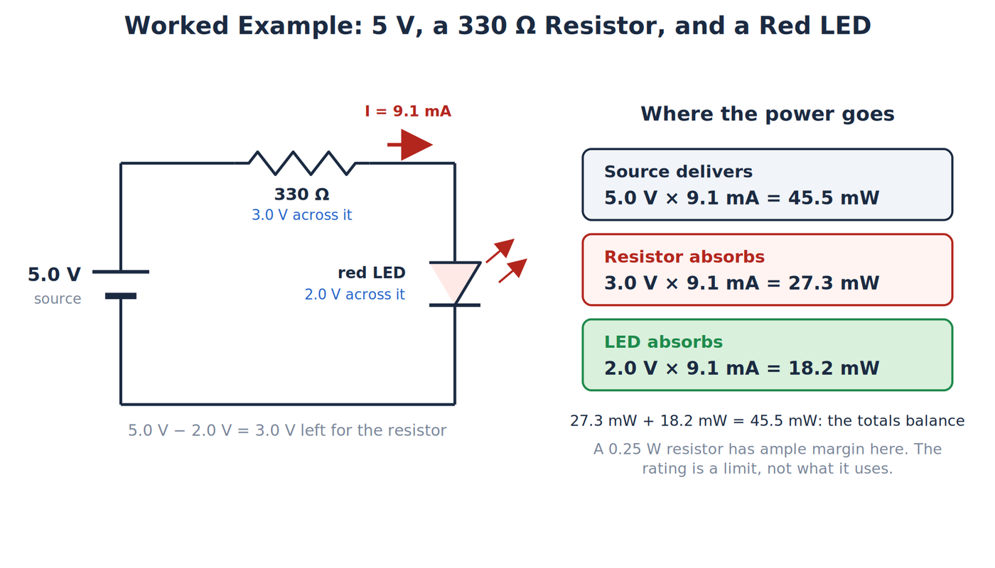
VR = 5.0V − 2.0V = 3.0V
Ohm’s law gives:
R = 3.0V / 0.010A = 300Ω
A nearby standard value is 330Ω. With the same 2.0V LED assumption, current becomes:
I = 3.0V / 330Ω = 0.00909A ≈ 9.1mA
Now calculate resistor power:
PR = VR × I = 3.0V × 0.00909A ≈ 0.027W
The cross-check agrees:
PR = I²R = (0.00909A)² × 330Ω ≈ 0.027W
A 0.25W resistor has ample nominal margin in this example. Its rating is a maximum dissipation under stated conditions, not the amount it automatically consumes. Real LED forward voltage varies, and resistor ratings depend on ambient temperature and installation, so verify the chosen parts before building.
So far, watts measure a rate, P = VI applies to any part at its operating point, and the I²R and V²/R forms apply only to ohmic resistors. The next section adds direction: a component can absorb power or supply it, and the sign of the result says which.
Sources, Loads, and Power Sign
Power has direction. A practical bookkeeping rule is the passive sign convention. If current enters a component’s terminal labeled positive, positive power means that component is absorbing energy. Negative power means it is supplying energy back to the circuit.
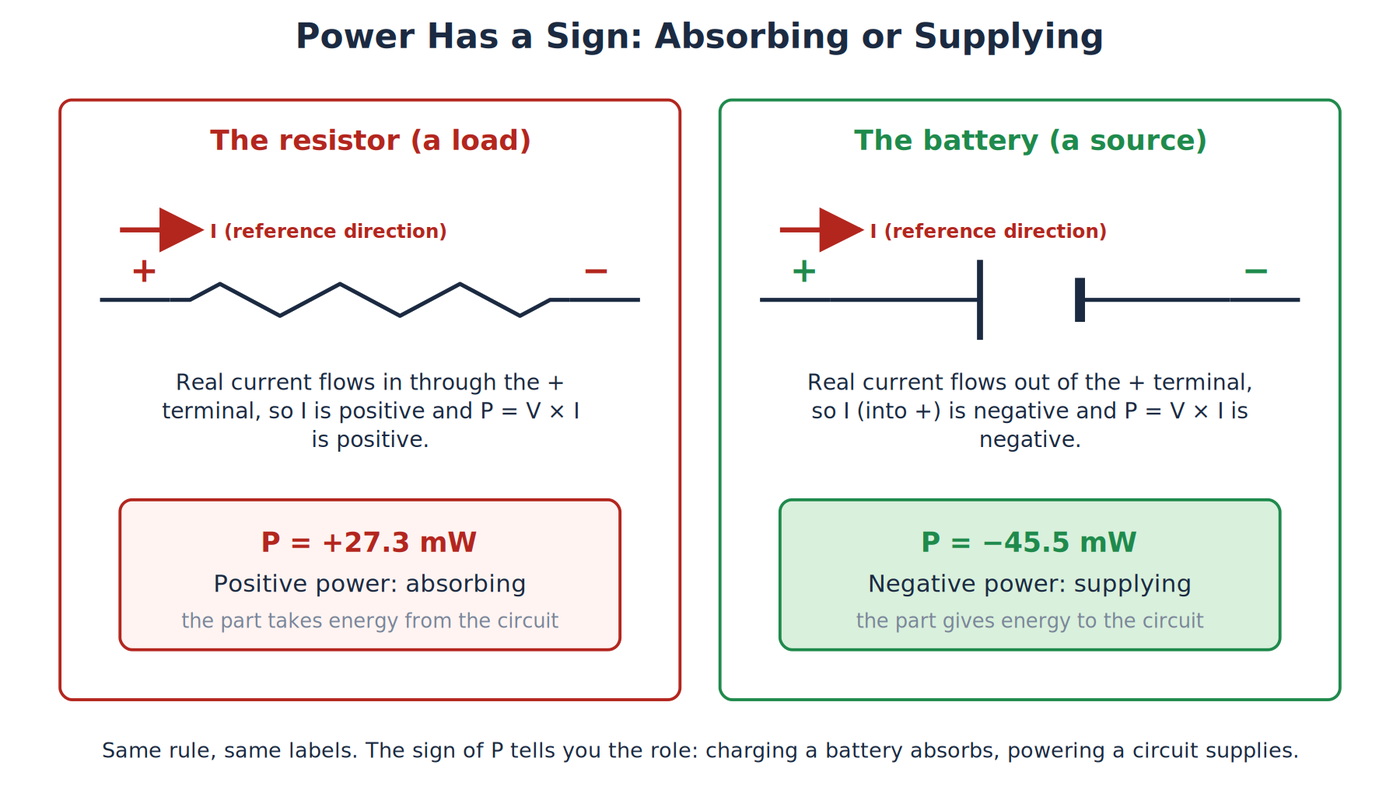
Consider the LED circuit. The source delivers power:
Psource = 5.0V × 9.1mA ≈ 45.5mW
The resistor absorbs about 27.3mW. The LED receives the rest:
PLED = 2.0V × 9.1mA ≈ 18.2mW
The totals balance: 27.3mW + 18.2mW = 45.5mW. The resistor’s share becomes heat. The LED converts its share into light and heat. No real LED turns all input power into visible light.
This same sign rule explains regenerative systems (ones that send energy back, like an electric car braking) and charging batteries. A battery supplying a circuit has delivered power. A battery being charged has absorbed power. The labels “source” and “load” describe what the part is doing at that moment.
Ratings and Efficiency
A voltage rating, current rating, or power rating is a boundary or specified operating condition. It is not a command that forces the circuit to use that amount. A 5V, 3A supply means the supply is intended to hold about 5V while providing current up to its rated limit under specified conditions. A small load may draw only 50mA.
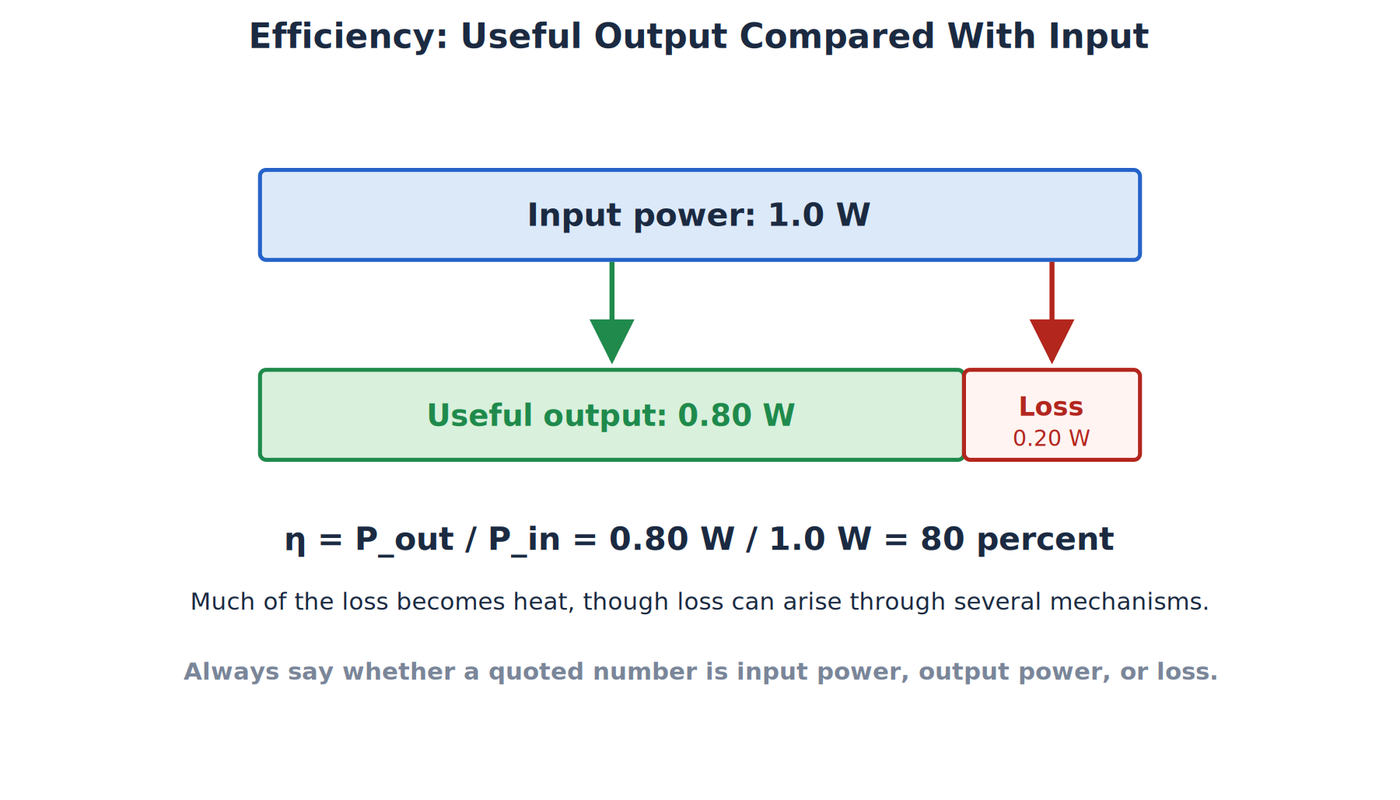
Efficiency, η, compares useful output power with input power:
η = Pout / Pin
If a converter takes 1.0W and delivers 0.80W, its efficiency is 80 percent. The difference is 0.20W of loss. Much of that may become heat, though loss can arise through several mechanisms. Always label whether a quoted value is input power, output power, or loss.
Power ratings also have conditions. A resistor’s printed quarter-watt rating may assume a particular ambient temperature and free airflow. Operating below the maximum adds margin, but complete thermal design and derating (deliberately running a part well below its maximum rating) belong in later articles.
Average Power on AC and Pulsed Signals
When the voltage or current changes with time, the power changes too, so it helps to separate the instantaneous power at one moment from the average power over time. A resistor on an AC source dissipates the same average power as a DC source of equal RMS value:
P = Vrms² / R
With the 12V RMS sine wave from the article on alternating current across a 100Ω resistor, P = (12V)² / 100Ω = 1.44W, the same as 12V of DC. The instantaneous power swings between zero and a peak. The peak voltage is about 17V, so the peak power is (17V)² / 100Ω ≈ 2.9W, which is twice the average. For a sine wave across a resistor, the average power is half the peak power. This is why a resistor's rating should be checked against the average power and why short peaks above the rating do not necessarily overheat it.
Pulsed signals work the same way. A pulse-width-modulated output switches a load fully on and fully off, and the duty cycle is the fraction of each period that the output is on. If a 5V output drives a 100Ω load, the power while on is (5V)² / 100Ω = 0.25W. At a 25 percent duty cycle, the average power is 0.25 × 0.25W = 0.0625W. Dimming a lamp or slowing a motor with PWM changes the average power in exactly this way, and a part's temperature follows the average, provided the pulses are fast compared with how quickly the part heats and cools.
Maximum Power Transfer
A real source has internal resistance, which was introduced in the article on direct current. The power it delivers to a load depends on how the load resistance compares with that internal resistance. Consider a 6V source with 2Ω of internal resistance and several different load resistances:
| Load resistance | Current | Power in the load | Efficiency |
|---|---|---|---|
| 1Ω | 2.0A | 4.00W | 33 percent |
| 2Ω | 1.5A | 4.50W | 50 percent |
| 4Ω | 1.0A | 4.00W | 67 percent |
| 8Ω | 0.60A | 2.88W | 80 percent |
Each current comes from I = 6V / (2Ω + R), and the load power is I²R. The load receives the most power, 4.5W, when its resistance equals the source's internal resistance. This is the maximum power transfer condition. At that point the source delivers 6V × 1.5A = 9W in total, and half of it is lost inside the source, so the efficiency is 50 percent.
The table shows the tradeoff: a load can take either the most power or the best efficiency, and the two occur at different resistances. Matching is used where the signal is small and the aim is to get as much of it as possible, as in radio and audio circuits. Power supplies are designed the other way, with an internal resistance far below the load so that nearly all the power reaches it.
Worked Example: Heat in a Linear Regulator
A linear voltage regulator lowers a supply voltage by turning the excess into heat. It passes the load current straight through, so the input current equals the output current, and the power lost is the voltage it drops multiplied by that current.
Suppose a regulator turns 12V into 5V for a load that draws 200mA:
Pout = 5V × 0.200A = 1.0W
Pin = 12V × 0.200A = 2.4W
Ploss = (12V − 5V) × 0.200A = 1.4W
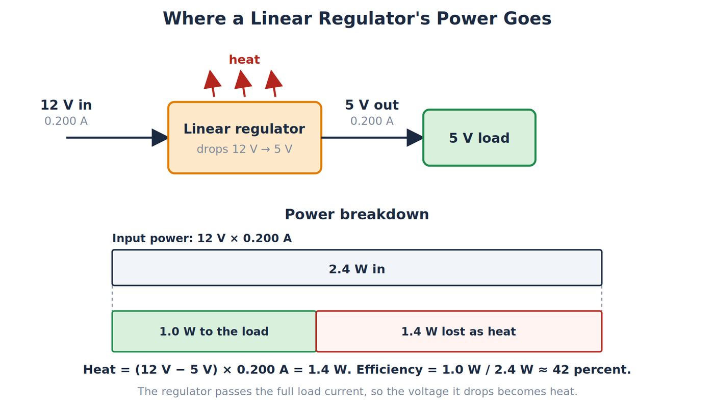
The regulator delivers 1.0W to the load and turns 1.4W into heat. Its efficiency is 1.0W / 2.4W ≈ 42 percent. A regulator in a small package such as a TO-220 can get very hot at 1.4W without a heat sink. Two things reduce the loss: a lower input voltage, which cuts the voltage drop, or a switching regulator, which does the same job at much higher efficiency. How both work is covered in a later article on voltage regulators.
Planning a Power Budget
A power budget adds up what every part of a project draws so the supply can be chosen with confidence. List each load, find its current at the supply voltage from the datasheet, and add the currents. Use the peak value for anything that draws current in bursts, such as a motor or a wireless radio.
As an example with assumed values, a 5V project has a microcontroller board that draws 50mA, eight LEDs at 10mA each (80mA), and a small servo that draws up to 500mA when it moves. The total is 50mA + 80mA + 500mA = 630mA. At 5V that is 5V × 0.630A = 3.15W. A supply rated for 1A leaves about 37 percent headroom, which is within the common practice of leaving 20 to 50 percent above the expected peak.
Wiring has limits too. Breadboard contacts and thin jumper wires are commonly rated for only about 1A or less, and all wiring has some resistance. Current through 0.1Ω of wiring at 1A drops 0.1V and dissipates P = I²R = (1A)² × 0.1Ω = 0.1W. That is small, but at 5A the same wiring would drop 0.5V and dissipate 2.5W, enough to warm the wire noticeably. Heavier loads need thicker wire and proper connectors.
A Safe Low-Voltage Measurement
The LED resistor calculation makes a good low-voltage demonstration. Use a current-limited 5V supply, a red LED, and a verified 330Ω resistor rated for at least 0.25W. Confirm the LED polarity before applying power.
Measure voltage across the resistor with the meter in parallel. To measure current, power down, move the red lead to the correct current jack, break the loop, and insert the meter in series. Start on a suitable current range. Never place a meter configured for current directly across a source, because that creates a very low-resistance path.
Measuring power directly
Several instruments report power without a calculation. A USB power meter placed between a charger and a device displays the voltage, the current, and usually the power and the accumulated energy. If it shows 5.05V and 0.42A, the power is 5.05V × 0.42A ≈ 2.12W. A bench power supply with a display does the same for whatever it powers. The meter itself drops a small voltage and uses a little power, so readings are most reliable when the load is much larger than that overhead. Line-powered watt meters exist, but those sit between the outlet and a plug-in device and should only be used as designed, never opened or modified.
If you measure 2.98V across the resistor and 9.0mA through it, calculate both ways:
P = 2.98V × 0.0090A = 0.0268W
P = (0.0090A)² × 330Ω = 0.0267W
The small difference comes from rounded readings and part tolerance. Stop if a component becomes unexpectedly hot, and do not use a short circuit as a load.
A Short History of the Watt
The watt is named for James Watt (1736–1819), a Scottish instrument maker and engineer. His work was on steam engines, not electricity. In the 1760s and 1770s he improved the Newcomen steam engine by adding a separate condenser, which made the engine far more efficient and helped make steam power practical for mines, mills, and factories.
Watt also needed a way to tell customers what an engine could do. Many of them were replacing horses, so he compared engine output with the work a horse could do turning a mill. His estimate was about 33,000 foot-pounds of work per minute, which is 550 foot-pounds per second. That figure became the horsepower, and it equals about 746 watts in today's units. The unit itself came later and did not come from Watt: it only named a rate of doing work, which is the same quantity whether the source is a steam engine, a horse, or an electric current.
Electrical engineers of the nineteenth century needed practical units for the new telegraph and power industries. In 1882, the engineer C. William Siemens proposed in a speech to the British Association for the Advancement of Science that the unit of power be named the watt, defined as the power of one ampere flowing through a potential difference of one volt. That matches the relationship P = VI used in this article. The name was adopted internationally by 1889, and a London conference in 1908 fixed the "international watt" for electrical measurement. In 1948 the watt was redefined as one joule per second, and the 11th General Conference on Weights and Measures included it in the International System of Units (SI) in 1960. The same unit now measures a lightbulb, a motor, and a power plant.
Common Misconceptions
- “Watts are stored.” Energy is stored. Watts describe how fast it is transferred.
- “A 3A supply pushes 3A.” The load and source behavior determine current; the rating states a limit.
- “Higher resistance always means more power.” The result depends on whether voltage or current stays fixed.
- “A 0.25W resistor always uses 0.25W.” That value is a rating, not an automatic operating point.
- “Low voltage cannot overheat anything.” High current can heat wires, connectors, batteries, and components quickly.
Related Articles
- How Ohm’s Law Works provides the V = IR relationship used to derive the resistor power formulas.
- How Electrical Energy Works follows power over time and separates watts from watt-hours.
Wrapping Up
Electrical power is the rate of energy transfer, measured in watts or joules per second. Voltage and current together set power through P = VI. Ohmic resistors also allow P = I²R and P = V²/R. Signs tell us whether a component is supplying or absorbing energy, ratings define limits, and efficiency compares useful output with input. Use calculations before building, verify them with safe low-voltage measurements, and leave enough component margin for real conditions. Power multiplied by time gives energy, and that relationship, including the difference between watts and watt-hours, is covered in How Electrical Energy Works.
Hack The World and Make Awesome.