How Alternating Current (AC) Works: Mastering Fundamental Electronics Part 06
Watch a child on a playground swing. The swing moves forward, slows, stops for an instant, and then moves back, and it repeats this at a steady rate. Its direction keeps reversing, yet a swing carries real energy the whole time. Alternating current, or AC, behaves in a similar way. The current in the circuit reverses direction over and over, and the voltage reverses polarity with it.
AC is not limited to the power at a wall outlet. It also describes audio signals from a microphone, radio signals in an antenna, the output of a transformer, and the test signals a function generator produces. These signals can take many shapes, but the sine wave is the standard one for learning, because it is smooth, common, and gives clean definitions of frequency, phase, and root-mean-square (RMS) values.
This article covers what alternates in an AC circuit, how to read a sine wave, how frequency and period are measured, and why one AC voltage can be quoted in several different ways. It also covers how a multimeter and an oscilloscope measure AC, how a rotating generator produces it, and why transformers made AC the choice for power distribution. The calculations use ideal sine waves and isolated low-voltage sources. Line power, the AC supply from a wall outlet, is explained here but is not something to measure as a beginner.
What Alternates
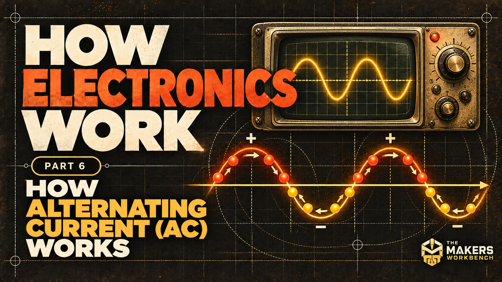
Current is the rate at which electric charge passes a point. In an AC circuit, that current reverses direction over time. The voltage reverses polarity too, so the terminal that is positive during one part of the cycle is negative during another.
Picture a resistor connected to a sinusoidal source. During the positive half-cycle, conventional current (the direction we agree to draw current) passes through the resistor one way. During the negative half-cycle, the voltage polarity and the current direction both reverse. The energy delivered does not cancel out. Because voltage and current reverse together in a resistor, their product stays positive, so the resistor heats during both halves.
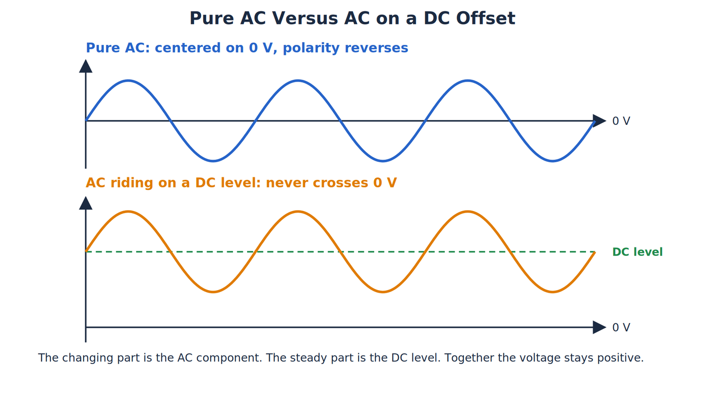
A waveform that changes without crossing zero is not pure AC. A pulsing voltage that stays positive is usually called pulsating DC. A changing signal can also be described as a DC level with an AC component riding on it, and the reference point you measure against decides which description fits.
Reading a Sine Wave
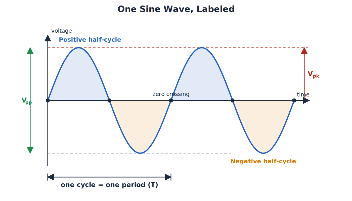
A waveform is a graph of a changing electrical quantity against time. A sine wave begins at its center line, rises to a positive peak, returns through zero, falls to a negative peak, and comes back to zero. That complete trip is one cycle.
The ideal voltage can be written:
v(t) = Vpk sin(ωt + φ)
The lowercase v is the instantaneous voltage, the value at one moment. Vpk is the peak voltage, ω is angular frequency, t is time, and φ is phase. Each of these gets its own definition in the next section. For now, read the graph: height gives the voltage, distance from left to right gives the time, and each crossing of the center line marks a polarity change.
Other shapes alternate too, including square waves, triangle waves, and distorted waveforms. Their shapes change how the useful quantities are calculated, so the sine-wave formulas in this article apply only to sine waves unless stated otherwise.
Frequency, Period, Angular Frequency, and Phase
The period, T, is the time required for one complete cycle. Frequency, f, is the number of cycles completed each second, measured in hertz (Hz). The two are reciprocals of each other:
f = 1 / T
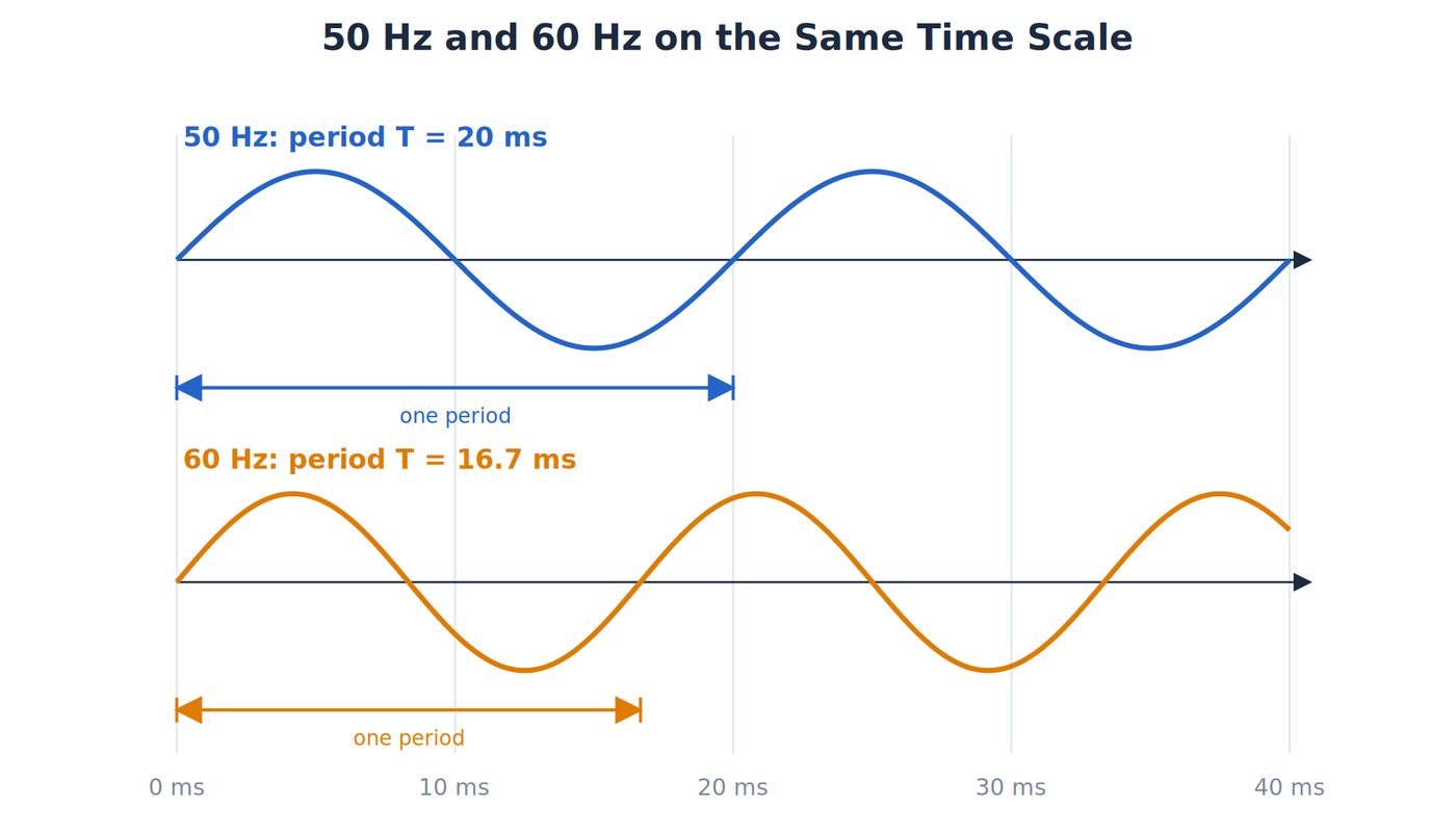
A 60Hz sine wave completes 60 cycles each second, so its period is:
T = 1 / 60Hz = 0.0167 s = 16.7ms
The voltage reaches the opposite polarity after half a cycle, about 8.33ms. The polarity therefore flips twice per cycle, or 120 times each second at 60Hz. Describing 60Hz power as "reversing 60 times per second" undercounts the reversals by half.
Angular frequency, ω, expresses the same repetition as an angle swept around a circle, measured in radians per second:
ω = 2πf
A radian is an angle unit, and one full circle is about 6.28 radians. One complete turn around the circle corresponds to one complete waveform cycle. At 60Hz, ω is about 377 radians per second.
Phase describes where a waveform is within its cycle compared with another waveform of the same frequency. Two ideal resistor waveforms that rise, cross zero, and peak together are in phase. Capacitors and inductors shift voltage and current relative to one another, and that behavior is covered in the later articles on reactance and impedance.
Line Frequency Around the World
The frequency of public power is a national or regional standard. The United States, Canada, and much of Central and South America use 60Hz, with a nominal outlet voltage of 120V. Most of Europe, Africa, and Asia use 50Hz, with a nominal voltage near 230V. Japan is an unusual case: the eastern part of the country runs at 50Hz and the western part at 60Hz, because early generating equipment was imported from different countries.
At 50Hz the period is 20ms and the angular frequency is about 314 radians per second. Equipment is designed around the local frequency. A transformer built for 60Hz can overheat on 50Hz, because the lower frequency lets the magnetic flux in its core rise higher on each cycle. Small motors and clocks that keep time from the line frequency change speed with frequency. Most modern switching power supplies accept 50 or 60Hz without trouble, which is why a laptop charger usually works in both regions with only a plug adapter.
The unit is named for Heinrich Hertz, whose experiments in the 1880s demonstrated that electromagnetic waves exist. It replaced the older phrase "cycles per second."
So far we have the shape of the waveform and the timing of its repetition. Frequency and period say how often the wave repeats, but neither says how large it gets, and a wave with several possible size measurements needs more careful labeling.
Peak, Peak-to-Peak, Average, and RMS
One sine wave can carry several voltage labels, and mixing them up causes real errors.
- Peak voltage, Vpk, is the largest magnitude measured from zero.
- Peak-to-peak voltage, Vpp, spans from the negative peak to the positive peak, so Vpp = 2Vpk.
- The arithmetic average of a centered sine wave over a complete cycle is zero.
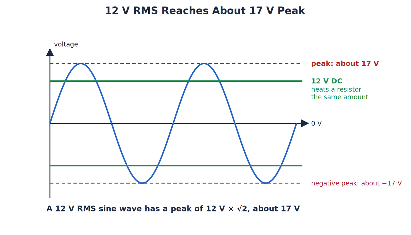
- Root-mean-square, or RMS, is the steady DC voltage that would heat a resistor by the same amount.
For a sine wave:
Vrms = Vpk / √2
The name describes the calculation: square the instantaneous values, find their mean, and take the square root. Squaring makes both the positive and negative halves contribute, which is why a zero average does not mean zero delivered power.
Nominal 120V line power is stated as an RMS value. For a sine wave, the peak is:
Vpk = √2 × 120V ≈ 170V
Line power can seriously injure or kill, and this lesson does not require measuring it. The same relationship is safer to see with an isolated 12V RMS sine source:
Vpk = √2 × 12V ≈ 17V
Its peak-to-peak voltage is about 34V. A meter or label that reads 12V RMS therefore does not mean the waveform stops at 12V. It means the waveform heats a resistor as much as a steady 12V would.
Measuring AC with a Meter and a Scope
The RMS value is the number most meters are meant to display, but not every meter calculates it the same way. How a meter handles the waveform decides whether its reading can be trusted.
Average-responding and true-RMS meters
A basic average-responding meter rectifies the signal (turns both halves positive), finds the average of the result, and multiplies it by 1.11. That factor is correct only for a sine wave, because for a sine wave the RMS value is about 1.11 times the rectified average. A true-RMS meter computes the square, the mean, and the square root of the actual waveform, so it stays correct for other shapes.
The difference shows up on non-sine signals. Take a square wave that swings between +5V and -5V. Its true RMS value is 5V. An average-responding meter sees a rectified average of 5V, multiplies by 1.11, and displays about 5.55V, which is 11 percent high. A triangle wave with a 5V peak has a true RMS value of 5 / √3 ≈ 2.89V. Its rectified average is 2.5V, so the same meter displays about 2.78V, which is about 4 percent low.
Two more limits apply to any meter. Its AC range works only up to a stated bandwidth, often a few kilohertz for a handheld meter, and readings fall off above that frequency. The AC function also normally blocks the DC component, so a signal that is AC riding on a DC level needs the meter's AC+DC mode or a separate DC measurement. Check the meter's manual for both.
Worked example: reading a scope trace
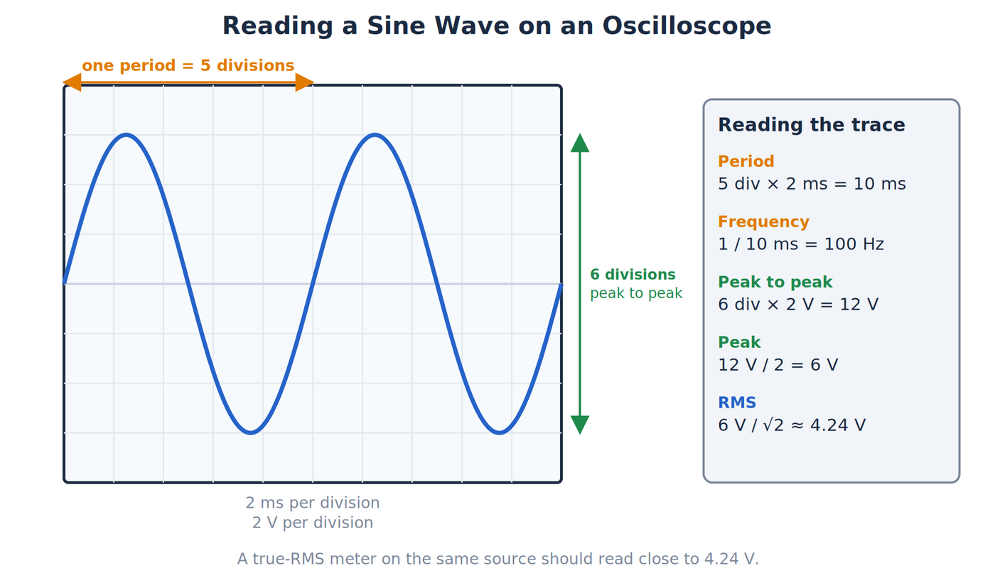
An oscilloscope shows the waveform directly, and each quantity in this article can be read from the screen. Suppose an isolated low-voltage source produces a sine wave on a scope set to 2ms per horizontal division and 2V per vertical division. One complete cycle spans 5 divisions horizontally, and the trace reaches from 3 divisions below the center line to 3 divisions above it.
- Period: 5 divisions × 2ms = 10ms.
- Frequency: f = 1 / 10ms = 100Hz.
- Peak-to-peak voltage: 6 divisions × 2V = 12V, so Vpk = 6V.
- RMS voltage: Vrms = 6V / √2 ≈ 4.24V.
A bench meter in true-RMS mode on the same source should read close to 4.24V. A reading that differs by much more than the meter's stated accuracy points to a non-sine waveform, a bandwidth limit, or a DC offset that the AC range is ignoring.
Rotating Motion into Alternating Voltage
A simple generator shows where a sine wave comes from. Imagine a wire loop rotating between magnetic poles. The amount of magnetic field passing through the loop, called magnetic flux, changes as the loop turns, and a changing magnetic flux induces an electromotive force, which is a voltage produced by that change.
At one orientation of the loop, the induced voltage crosses zero. A quarter-turn later, its magnitude is greatest. After a half-turn it crosses zero again, and during the next quarter-turn its polarity is reversed. After a full turn the cycle repeats. Slip rings (rotating metal rings with sliding contacts) keep the loop connected to the external terminals while it spins, so those terminals see the alternating polarity.
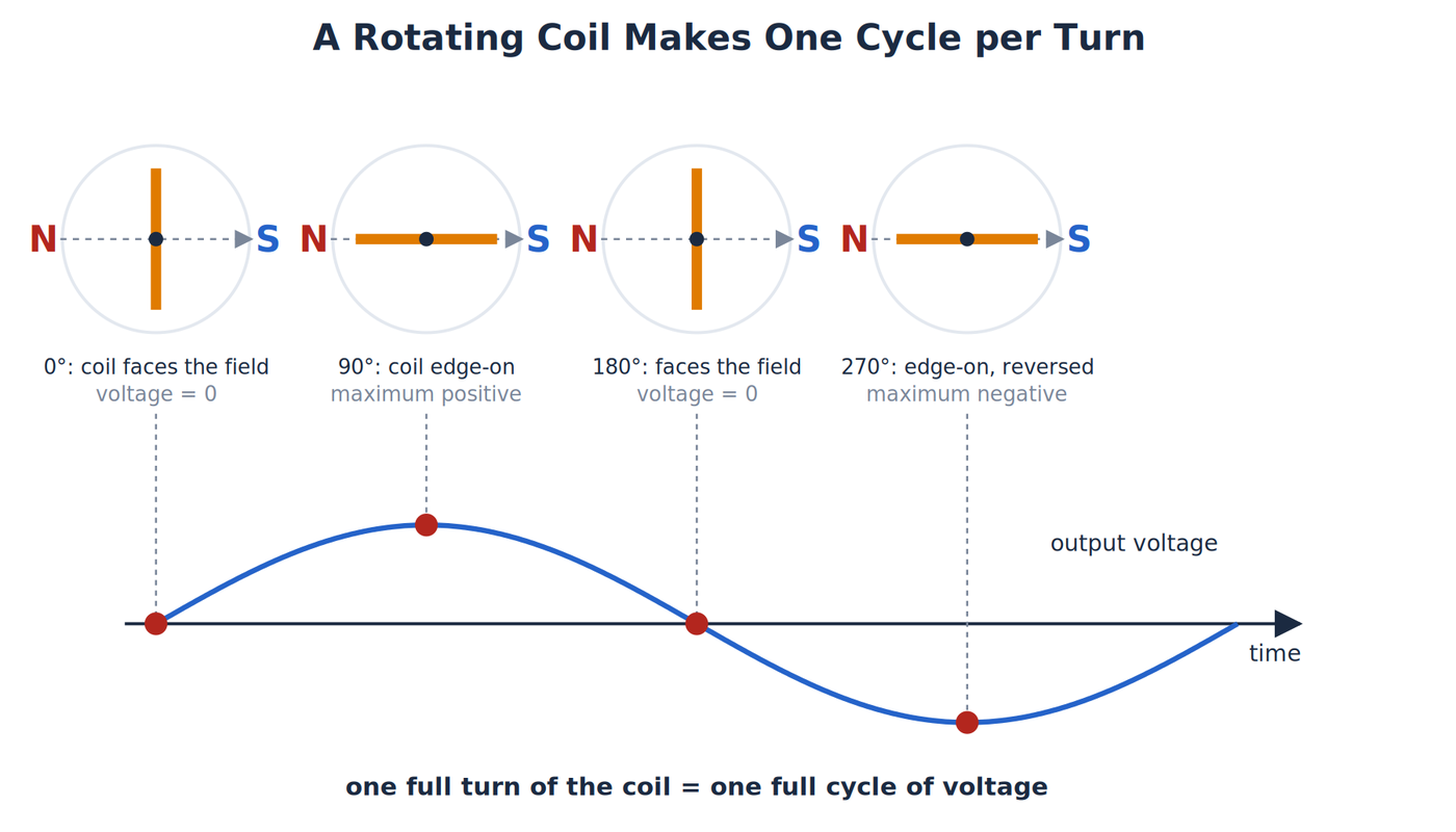
Real alternators differ from this single loop. Many rotate a magnetic field inside stationary windings, and most produce several phases, meaning several AC waveforms offset in time. The single loop is a teaching model, and it shows why rotation naturally produces a repeating voltage that reverses polarity.
Transformers and AC Distribution
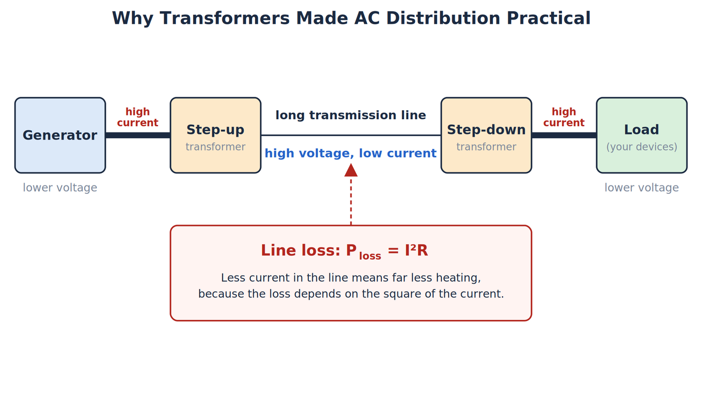
Generating AC is one half of a power system. Delivering it over long distances is the other half, and that is where AC has its main advantage. A transformer uses a changing magnetic field in one winding to induce voltage in another winding, and it can raise or lower the voltage as a result. This only works with a changing current, which is why transformers are an AC technology.
For the same transmitted power, higher voltage means lower current. Resistive loss in the line follows Ploss = I²R, so cutting the current sharply reduces the heat lost in the conductors. A transformer at the power plant raises the voltage for transmission, and another near the point of use lowers it again. Late nineteenth-century power systems gained a major practical advantage from this.
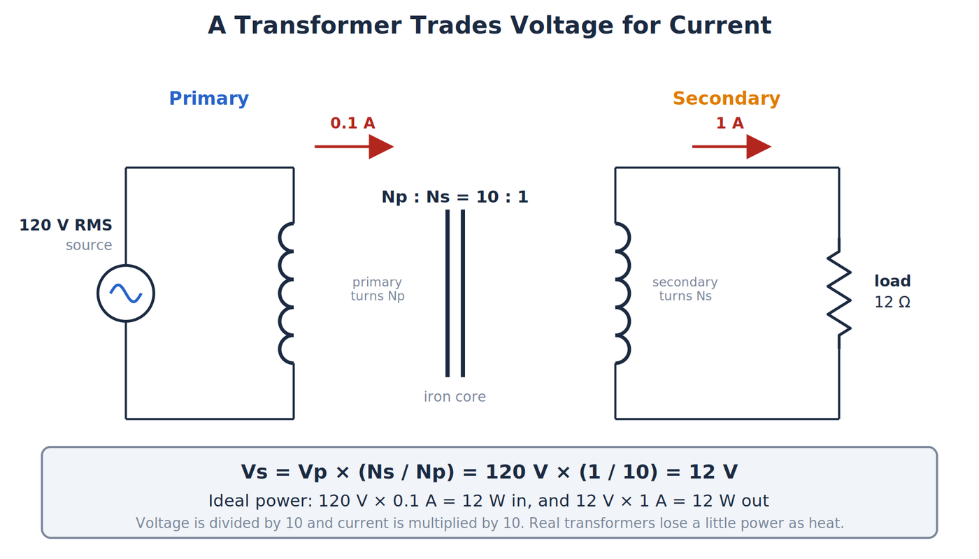
The ratio of the voltages follows the ratio of the turns of wire in the two windings:
Vs / Vp = Ns / Np
Vp and Np are the voltage and number of turns in the primary winding (the input side), and Vs and Ns are the same quantities for the secondary winding (the output side). A transformer with 10 times as many primary turns as secondary turns lowers 120V to 12V. If the secondary supplies 1A at 12V, that is 12W, and an ideal transformer draws the same 12W from its primary, which means 0.1A at 120V. The voltage drops by a factor of 10 and the current rises by a factor of 10 from primary to secondary. Real transformers lose some power as heat, so the primary draws slightly more than the ideal value.
The same transformer idea sits inside many small power supplies. A wall adapter for a low-voltage device traditionally uses a transformer to lower the line voltage, a rectifier to turn the AC into pulsating DC, a filter capacitor to smooth it, and sometimes a regulator. How those last three stages work is covered in the article on direct current. Many modern adapters are switching supplies, which rectify the line voltage first and then use a small high-frequency transformer, but the transformer's job is the same.
Large power systems use three-phase AC, which is three sine waves of the same frequency offset by one third of a cycle (120 degrees) from one another. With a balanced load, the total power delivered by three phases is constant from moment to moment, while a single-phase supply delivers power in pulses. Three-phase wiring also carries more power per conductor, so industrial motors and utility distribution use it. A typical US home receives a single-phase service with two 120V legs that are half a cycle apart, which provides 120V for most outlets and 240V between the legs for large appliances. Three-phase and split-phase wiring are outside the scope of this article, and wiring work on either belongs to qualified electricians.
The history is often reduced to Edison versus Tesla, but several people and companies shaped it. George Westinghouse's companies, Nikola Tesla's patents for multi-phase systems, William Stanley's transformer work, and many other engineers contributed. Public demonstrations such as the 1893 Chicago fair and the Niagara Falls project helped prove large AC systems. No single inventor created modern AC power alone.
AC in Electronics and Safe Observation
AC appears in electronics at voltages far below household levels. A microphone produces an audio signal that varies with sound, a radio circuit handles much faster alternating signals, and a small isolated transformer can provide low-voltage AC for experiments.
An oscilloscope displays voltage versus time, so it shows the shape, frequency, peak voltage, and offset of an AC signal. For a beginner observation, use only an isolated, extra-low-voltage source. Oscilloscope ground clips are often connected to protective earth, and clipping one onto the wrong node creates a short circuit. Before making any connection, confirm the instrument, the source isolation, the probe rating, and the grounding arrangement.
Common Misconceptions
- "AC is always a sine wave." A sine wave is common, but other shapes can alternate.
- "A zero average means no power." Voltage and current reverse together in a resistor, so both halves deliver energy.
- "120V is the peak." The common nominal rating is RMS. A sine wave at 120V RMS reaches about 170V peak.
- "Electrons travel from a power plant to a load and back." The charge carriers in a wire oscillate in place while the energy moves through the circuit and its electromagnetic fields.
- "Any meter reads AC voltage correctly." Average-responding meters are accurate only on sine waves, and every meter has a bandwidth limit.
- "Tesla invented AC by himself." Modern AC systems grew from the work of many people and organizations.
Related Articles
- How Direct Current (DC) Works explains one-direction current, steady and rippled DC, and real source behavior.
Wrapping Up
AC reverses its current direction and voltage polarity over time. A sine wave is described by its period, frequency, angular frequency, and phase, and its size can be given as a peak, peak-to-peak, average, or RMS value. A 12V RMS sine wave reaches about 17V at its peak, in the same way that a nominal 120V RMS wave reaches about 170V. True-RMS meters and oscilloscopes both measure these quantities, while a plain average-responding meter reads correctly only on a sine wave. A rotating loop in a magnetic field produces this waveform, and transformers made it practical to send AC over long distances at low current. Direct current is the other half of this comparison, so it is next.
Hack The World and Make Awesome.