How Electrical Resistance Works: Mastering Fundamental Electronics Part 03
Try drinking a thick milkshake through a coffee stirrer. It works, but it takes real effort, and you only get a trickle. Swap in a wide straw and the same shake comes up easily. Your lungs stayed the same, and the easier path made the difference.
Electrical resistance is that idea applied to electric charge. Every material and every component makes it harder, or easier, for current to pass for a given push from a voltage. Some paths, like a thick copper wire, are as easy as the wide straw. Others, like a long strand of thin nichrome wire, are the coffee stirrer. And when charge has to fight through a hard path, the energy it spends comes out as heat.
In this article I'll define resistance and its unit, show you what is happening inside the material, explain how a wire's length, thickness, and material set its resistance, look at what temperature does, and then show you how to measure resistance without fooling yourself. It builds on How Voltage Works and How Electric Current Works, but I'll define each term as it comes up, so you can start here if you prefer.
Resistance Is a Ratio
Resistance describes how strongly a component or path opposes current for a given voltage. The practical way to define it is with a ratio:
R = V / I
R is resistance, V is the voltage across the part, and I is the current through it. The unit is the ohm, written with the Greek letter omega (Ω), and defined so that:
1 Ω = 1 volt per ampere
In plain terms, if 1 volt across a part drives 1 amp through it, the part has 1 ohm of resistance. A part that lets only 1 milliamp through at that same volt has 1,000 Ω. The bigger the number, the harder the path.
For many materials at a steady temperature, doubling the voltage doubles the current, and the ratio R stays fixed. Parts that behave this way are called ohmic. Plenty of real parts don't, and I'll cover that below. The full workflow for solving voltage, current, and resistance problems is the subject of How Ohm's Law Works, so here I'll stay focused on what resistance is and why it changes.
That ratio tells you how much a part resists. It says nothing about why, so let's look inside the metal.
Scattering Inside a Conductor
A metal contains free electrons (the charge carriers that make up a current there) moving among a regular arrangement of atoms called a lattice. When a voltage pushes those electrons along, they don't glide freely. They keep bumping into things: atoms vibrating from heat, impurities, tiny defects, and the edges of the material. Each bump, called scattering, hands a little of the electrons' energy to the lattice.
That passed-along energy shows up as motion of the atoms, which is another way of saying it shows up as heat. This is why a toaster wire glows and why a phone charger gets warm. Resistance is the measurable result of all that scattering.
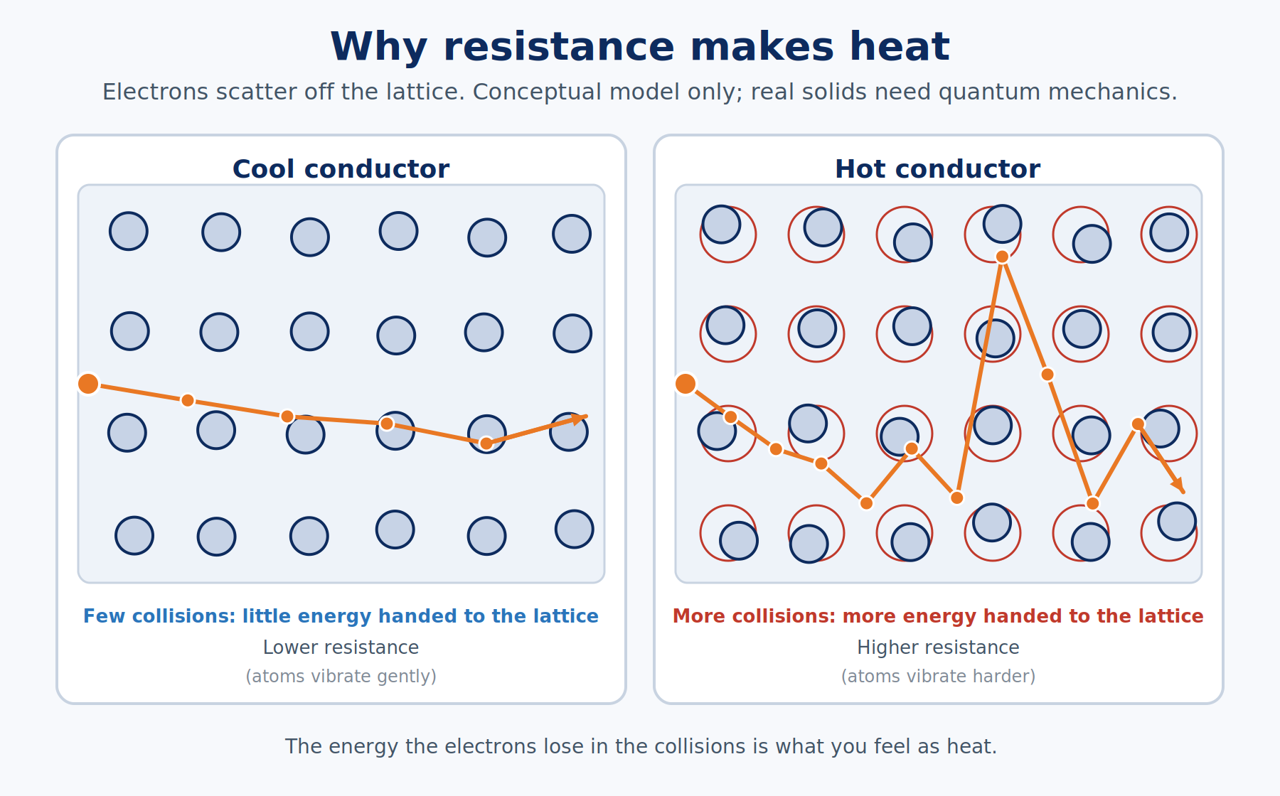
I should flag that this picture is a simplification. It is a classical model, and real solids are described by quantum mechanics. The bouncing-ball version is still useful for building intuition, but don't take the drawing literally.
Scattering explains the cause. What you can control is the shape of the conductor and what it is made of.
Length, Thickness, and Material
Resistance depends on the shape of the conductor and on what it is made of. For a uniform piece of material, the relationship is:
R = ρ × L / A
Here L is the length of the conductor, A is its cross-sectional area (the area you would see if you sliced straight across it), and ρ is the Greek letter rho, which stands for resistivity. Resistivity is a property of the material itself, measured in ohm-meters (Ω·m). It is not the same thing as resistance. Resistivity belongs to copper in general. Resistance belongs to this specific piece of copper wire.
Think about the shape this way. A longer wire gives the carriers more material to push through, so resistance goes up in proportion to length. A thicker wire gives them more parallel lanes, so resistance drops as the area grows. That is why the cables that carry heavy current are thick.
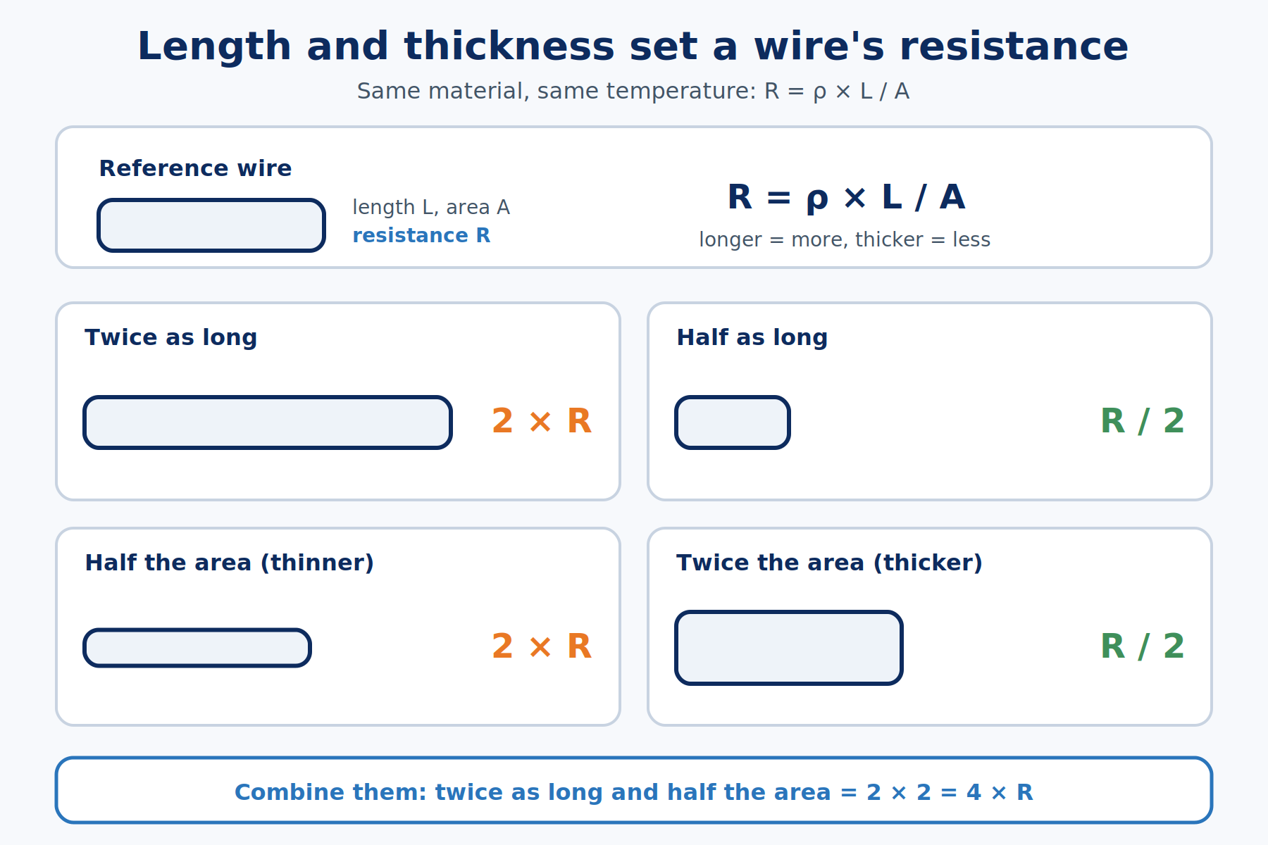
As a quick comparison, suppose wire B is made of the same material as wire A and is at the same temperature, but it is twice as long and has half the cross-sectional area. Then:
RB / RA = (2L / (A/2)) / (L / A) = 4
Wire B has four times the resistance. Now for a real number: a 10-meter run of 22 AWG copper wire (a common hookup wire size, with a diameter of about 0.64 mm) has a resistance of roughly 0.5 Ω at room temperature. Not much, but it adds up in long runs and at high currents.
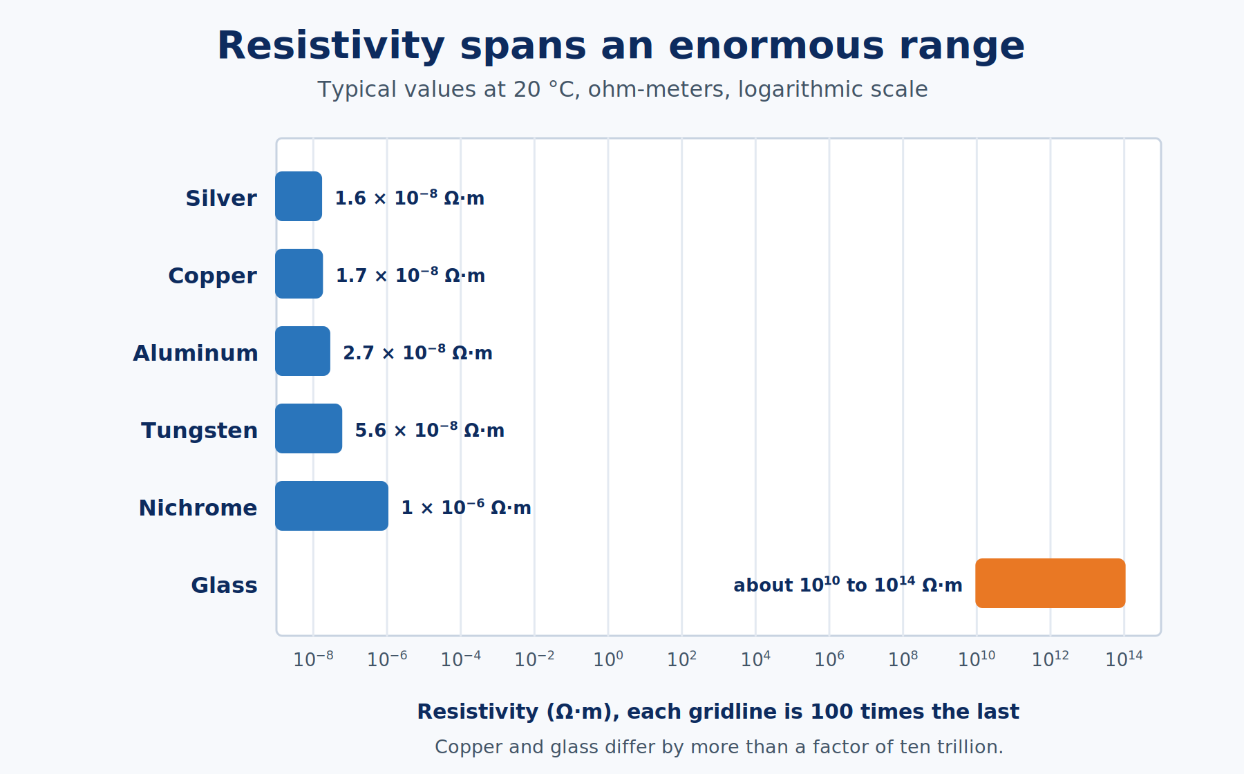
Materials differ enormously in resistivity. Some typical values at 20 °C (68 °F), rounded, are below.
| Material | Resistivity (Ω·m) | Typical use |
|---|---|---|
| Silver | 1.6 × 10⁻⁸ | Best metal conductor, used in contacts |
| Copper | 1.7 × 10⁻⁸ | Wiring, PCB traces |
| Aluminum | 2.7 × 10⁻⁸ | Power lines |
| Tungsten | 5.6 × 10⁻⁸ | Lamp filaments |
| Nichrome | 1.0 × 10⁻⁶ | Heating elements |
| Glass | about 1010 to 1014 | Insulator |
The last row spans an enormous range, which is why the chart below uses a logarithmic scale, where each step up the axis is ten times bigger. Copper and glass differ by more than a factor of ten trillion.
Resistivity's reciprocal, 1/ρ, is called conductivity. A good conductor has high conductivity and low resistivity. Ordinary conductors still have some resistance. A material with exactly zero resistance is called a superconductor, and that only happens under strict conditions (typically very low temperatures), so it won't show up on your bench.
Shape and material set a baseline. Heat then moves that baseline, because the atoms in the lattice never sit still.
Temperature Changes Resistance
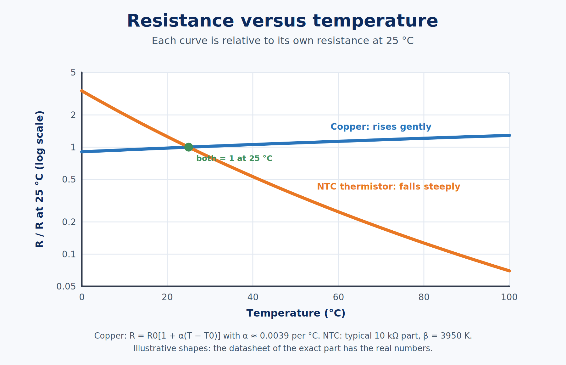
Heat makes the lattice atoms vibrate harder, which means more scattering. For most metals, that causes resistance to rise as the temperature rises. Over a limited range, you can approximate the change with:
R = R0 × [1 + α × (T − T0)]
R0 is the resistance at a reference temperature T0, T is the new temperature, and α (alpha) is the temperature coefficient of resistance, a number that says how quickly resistance changes per degree. For copper near room temperature, α is about 0.0039 per °C. Take a 100 Ω copper coil at 20 °C and warm it to 70 °C:
R = 100 × [1 + 0.0039 × (70 − 20)] = 100 × 1.195 ≈ 119.5 Ω
A 50 °C warm-up added nearly 20 percent. This straight-line formula is an approximation. It works well over a modest range and gets less accurate as the temperature moves far from the reference.
Not every part follows the metal pattern. A thermistor is a resistor built to change dramatically with temperature. A common type, the NTC (negative temperature coefficient) thermistor, does the opposite of a metal: its resistance falls as it heats up. Semiconductors often behave this way too. In the chart below, the copper line is straight and gentle, while the NTC curve plunges. The NTC curve is based on a typical 10 kΩ part at 25 °C, so treat it as an illustration. The datasheet for the exact part you use has the real numbers.
So far, resistance is a ratio measured in ohms, it comes from scattering, and it depends on length, area, material, and temperature. That last point is what breaks the idea that a part has one fixed number.
Ohmic and Non-Ohmic Parts
Back to the word "ohmic." An ideal resistor at a steady temperature has a straight-line relationship between voltage and current: plot current against voltage, and you get a line through the origin. The steeper the line, the lower the resistance.
The tungsten filament inside an old-style incandescent lamp is a clear counterexample. When you first switch it on, it's cold and its resistance is low, so a big surge of current flows. That current heats the filament to thousands of degrees, its resistance climbs by a large factor, and the current settles to a lower steady value. The V-I plot bends instead of staying straight. A diode, which only passes current in one direction, is another strongly non-ohmic part, covered in its own article.
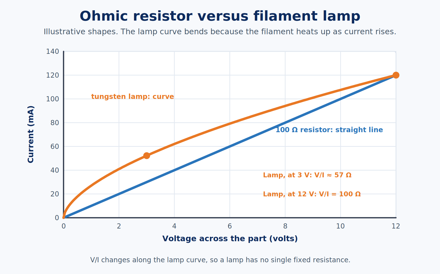
The lesson is that "R = V/I" is a perfectly valid calculation for any single operating point, but only for an ohmic part does the answer stay the same when the voltage changes. Don't assign one fixed resistance to a lamp, a thermistor, or a diode.
Resistance also turns electrical energy into heat, at a rate called power. With current I flowing through resistance R:
P = I² × R
Take a 100 Ω resistor with 20 mA (0.020 A) flowing through it: P = (0.020)² × 100 = 0.040 W, or 40 milliwatts. Power gets its own article, How Electrical Power Works (coming soon). For now, notice that a resistor's ohm value does not tell you how much heat it can handle. A tiny resistor and a fat one can both be 100 Ω. The fat one can usually shed more heat, so body size tends to track power rating, not resistance.
Everything above eventually gets checked with a meter, and resistance is the one measurement where careless connections give you a wrong answer instead of a blown fuse.
Measuring Resistance
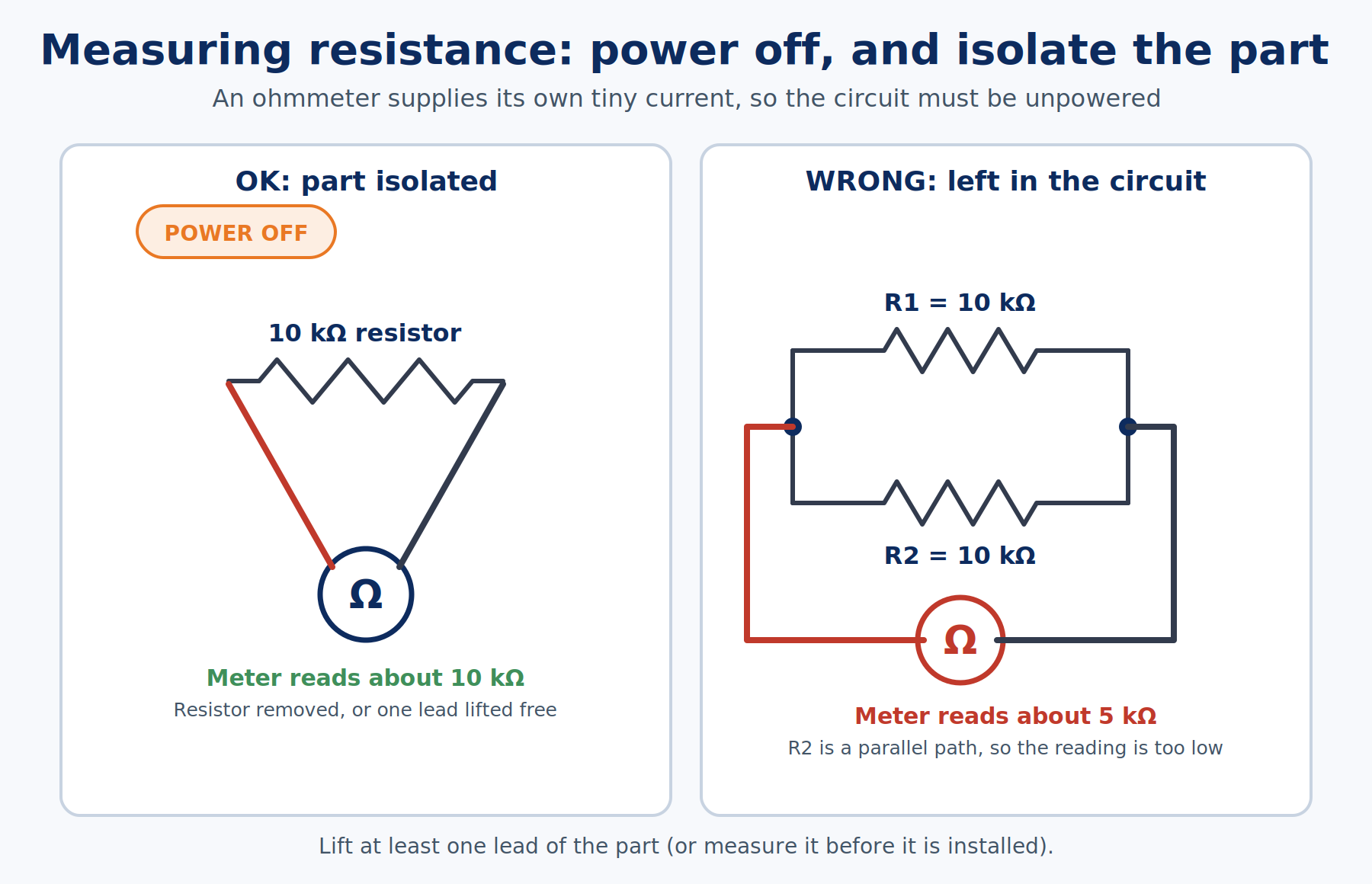
A multimeter measures resistance with a built-in ohmmeter. It sends a tiny known current through the part, measures the resulting voltage, and calculates R for you. The critical rule: only measure resistance on a part with no power connected. An ohmmeter has its own small source, and any other voltage in the circuit will give you nonsense (and might damage the meter).
Try this on a loose resistor:
- Turn the dial to the ohm (Ω) position, with the leads in COM and the V/Ω jack.
- Touch the two probe tips together. The display should drop to nearly 0 Ω. Any small leftover number is the resistance of the test leads and your contact. Note it, because it matters when you measure very small resistances.
- Touch the probes to the two ends of the resistor. Hold the probes by their insulated handles, not the metal tips, so your own body's resistance doesn't sneak into the reading.
- Compare the reading with the resistor's marked value. Common resistors are accurate to within 5 percent, and some are 1 percent.
If you want to measure a resistor that is already soldered or plugged into a circuit, lift at least one lead out first. Otherwise other parts of the circuit form extra paths in parallel with the resistor, and the meter reports a value lower than the real one. Discharged capacitors can also confuse a reading, and charged ones can be hazardous, which is one more reason to power down and wait.
For very small resistances, lead and contact resistance can swamp the value you are after. The precision answer is a four-wire (Kelvin) measurement, which uses separate pairs of wires for pushing current and sensing voltage. It deserves its own article, How Four-Wire Kelvin Measurements Work (coming soon).
If you don't have a meter, the Circuit Lab section below lets you read a simulated circuit's voltage and current and work out the resistance from them.
Try Resistance in the Circuit Lab
Resistance is a ratio, so this simulation lets you compute it from two readings. Two separate loops share one 5 V supply. One holds a 10 kΩ fixed resistor. The other holds an NTC thermistor (a resistor whose value falls as it heats up) that is also 10 kΩ at 25 °C. The comparison to make: voltage divided by current gives each part's resistance, and only the thermistor's changes with temperature.
If you aren't running it: both loops carry 0.5 mA at the start (5 V divided by 10,000 Ω). Heat the thermistor to 75 °C and its loop carries about 3.4 mA, which means its resistance has dropped to roughly 1.5 kΩ. The fixed resistor's loop stays at 0.5 mA.
The Circuit Lab circuit is connected like this:
| Net | Connects | Why |
|---|---|---|
| FIXED_TOP | R1 pin 1 and supply + | Puts the full 5 V on the fixed resistor |
| FIXED_BOTTOM | R1 pin 2 and supply − | Returns the fixed resistor's current to the supply |
| THERMISTOR_TOP | T1 pin 1 and supply + | Puts the full 5 V on the thermistor |
| THERMISTOR_BOTTOM | T1 pin 2 and supply − | Returns the thermistor's current to the supply |
The supply is set to 5 V, R1 is 10 kΩ, and T1 is a thermistor set to 25 °C.
Using the Circuit Lab
- Run, the green button in the toolbar, starts the simulation. Reset at the top right puts the circuit back the way it started (it asks you to confirm first).
- Right-click a part and choose Properties… to change a value, such as the thermistor's temperature.
- The multimeter is the meter icon in the toolbar. To move a probe, click the Red or Black button on the meter, then click a part's lead or a hole on the desk. The reading is the red probe's point minus the black probe's point, so swapping the probes flips the sign. In this lab the meter opens already connected. Drag the meter by its title bar (the word Multimeter) to move it, so it does not sit on top of the circuit, and use the × to close it.
- Zoom by holding Ctrl (Command on a Mac) and turning the mouse wheel over the desk. Turning the wheel without a key pans the desk instead.
- Open full workbench, at the top right, opens the same circuit on its own page, where you can add parts and wires.
To use the resistor and thermistor circuit, follow these steps:
- Press Run.
- The multimeter is already open in V DC mode, with its probes on the two ends of R1. You should read about 5 V.
- Switch the meter to A DC (click the mode button on the meter). It now reads R1's current, about 0.5 mA (the meter shows it as 500 µA).
- Divide: 5 V ÷ 0.0005 A = 10,000 Ω, or 10 kΩ. That is resistance as a ratio.
- Move both probes to the thermistor's two leads and read its voltage (about 5 V) and current (about 0.5 mA). The ratio is the same 10 kΩ at 25 °C.
- Right-click the thermistor, choose Properties…, and drag the Temperature slider to 75 °C. If the circuit is running, press Stop first, close the card with Esc when you are done, then press Run again. Its current rises to about 3.4 mA (the meter shows 3.352 mA), so 5 V ÷ 0.0034 A is roughly 1.5 kΩ. R1 has not moved.
The fixed resistor's ratio stayed at 10 kΩ while the thermistor's ratio fell as it got hot.
A short history of the ohm
Georg Simon Ohm published the relationship between voltage, current, and resistance in 1827 after careful experiments on conductors. The scientific world didn't greet it warmly at first, and Ohm struggled for recognition for years. The Royal Society finally awarded him its Copley Medal in 1841. In the 1860s, a committee of the British Association worked on standardizing electrical units, and the unit of resistance was named the ohm in his honor. Today, resistance is realized through quantum electrical standards rather than a particular coil of wire, but the unit is the same one Ohm's name made famous.
Common Misconceptions
- "Resistance uses up current." Current is not consumed. Resistance affects how much current a given voltage can drive and turns electrical energy into heat.
- "A good conductor has zero resistance." Even copper has some. It's just small.
- "A bigger resistor always has more ohms." Body size usually relates to power handling. The value comes from the construction and markings.
- "R = V/I means every part has one fixed resistance." That's true for ohmic parts at stable conditions. A lamp, a thermistor, or a diode is not that simple.
- "You can use an ohmmeter on a live circuit." Don't. Remove power first.
Related articles
- How Voltage Works and How Electric Current Works cover the two quantities resistance connects.
- How Ohm's Law Works turns R = V/I into a full problem-solving method.
- How Electrical Power Works (coming soon) explains how resistance turns electrical energy into heat.
- How Resistors Work (coming soon) looks at the components made to provide resistance on purpose.
- How Thermistors Work (coming soon) digs into parts whose resistance changes with temperature.
Wrapping up
Resistance, measured in ohms, tells you how strongly a part opposes current for a given voltage. Inside a metal, it comes from electrons scattering off the lattice and handing energy to it as heat. For a uniform conductor, R = ρL/A, so longer and thinner means more resistance and shorter and thicker means less, with the material's resistivity setting the scale. Most metals gain resistance as they warm, while thermistors and semiconductors can go the other way. Only ohmic parts keep one fixed value, and an ohmmeter should only ever be used on an unpowered part.
Hack The World and Make Awesome.