How Electric Current Works: Mastering Fundamental Electronics Part 02
Imagine standing next to a turnstile at a stadium gate, clicker in hand, counting people as they pass through. If 50 people come through in a minute, your count is 50 people per minute. The count says nothing about how big the crowd is or how excited it is, only how many go by in a given amount of time.
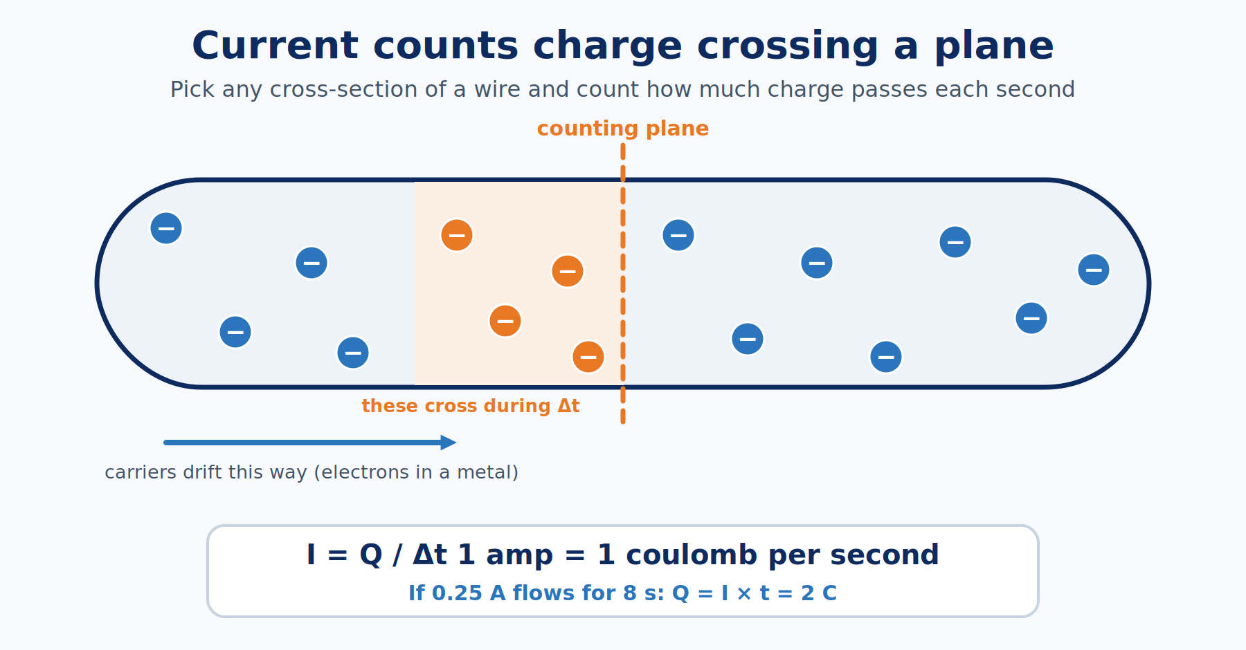
Electric current is that same kind of count. Instead of people, you count electric charge. Instead of a turnstile, you pick any cross-section of a wire and watch how much charge crosses it each second. When someone says a phone charger delivers "2 amps," they mean a certain amount of charge is passing through the cable every second.
In this article I'll define current precisely, show you the unit that measures it, explain what is moving inside a wire (the answer is stranger than "electrons racing along"), clear up why diagrams show current going the opposite way from the electrons, and walk through how to measure it without damaging your meter. You don't need to have read anything else first, though How Voltage Works pairs nicely with this one.
Current Is a Count of Charge
Electric charge is a property of matter that comes in positive and negative kinds, and it is measured in coulombs (C). Electric current is the rate at which net charge passes through a chosen surface. If a small amount of charge ΔQ crosses during a time Δt, the average current is:
I = ΔQ / Δt
The symbol I stands for current (it comes from the French word for intensity). The unit of current is the ampere, usually shortened to amp and written A. One amp is one coulomb of charge passing per second:
1 A = 1 C/s
A coulomb is a big pile of charge, roughly 6.24 × 10¹⁸ elementary charges, where an elementary charge is the size of the charge on a single electron or proton. So even a modest current means an enormous number of charge carriers streaming through every second. As a worked example, if 0.25 A flows for 8 seconds, the total charge that moved is:
Q = I × t = (0.25 A)(8 s) = 2 C
That is about 1.25 × 10¹⁹ electrons' worth of charge.
You have probably seen "mAh" on a battery or power bank. That is milliamp-hours, and it counts charge, not current alone. One amp-hour equals 3,600 coulombs (one amp for 3,600 seconds). It tells you how much charge a battery can move, which is related to, but not the same as, how much energy it holds. That energy question is the job of How Electrical Energy Works (coming soon).
That is the whole definition: count the charge, divide by the time. The next thing worth knowing is what the charge is riding on.
What Carries the Charge
The things that move and make up a current are called charge carriers, and they vary by material.
- In a metal such as a copper wire, the carriers are electrons. Metals have electrons that aren't tied to any one atom, which is what makes them good conductors.
- In an electrolyte (a liquid such as salt water or battery acid that contains dissolved ions), the carriers are ions, atoms or molecules that have gained or lost electrons and so carry a net charge. Both positive and negative ions move, in opposite directions.
- In a semiconductor (the material in transistors and chips), the carriers are electrons and holes, places where an electron is missing and which behave like moving positive charges. That story gets a full treatment later in the series.
For the circuits on your workbench, picture electrons in copper. But keep in mind that current is defined by moving charge, not by electrons specifically.
In a copper wire the carriers are electrons, which raises an obvious worry about how fast they have to travel. The answer surprises almost everyone.
Drift Speed and the Instant Lamp
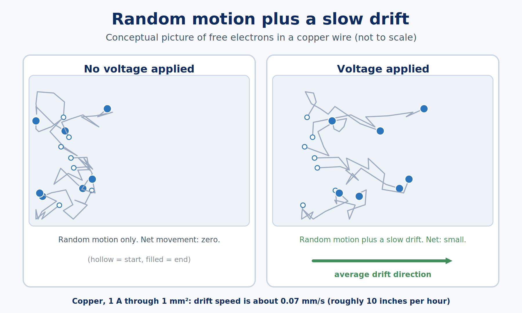
Inside a copper wire, those free electrons are already zooming around randomly at high speed, bouncing off atoms, because of heat. With nothing connected, that motion averages out to zero: just as many go left as go right, so there is no net flow.
Connect a source and an electric field sets up along the wire. Each electron still bounces around in the same chaotic way, but now there is a slight bias, a gentle push in one direction. Add that up and you get a slow average motion called drift. The average speed of that drift is the drift velocity.
For readers who like a formula, current can be written as:
I = n × q × A × vd
where n is the number of mobile carriers per cubic meter, q is the charge on each carrier, A is the cross-sectional area of the wire, and vd is the drift velocity. Copper has roughly 8.5 × 1028 free electrons per cubic meter. Put 1 amp through a wire with a cross-section of 1 square millimeter and you get a drift velocity of about 0.07 millimeters per second, or roughly 10 inches per hour.
Ten inches per hour. Yet when you flip a switch, the lamp lights almost instantly. How does that work? The electrons in the wire were already everywhere along the wire, so when the push arrives, they all start drifting at once, like a pipe that is already full of water. The change in the electric field, along with the energy it carries, travels along the wire far faster than any single electron drifts. The signal doesn't wait for an electron to travel from the switch to the bulb. (The exact speed depends on the wire's geometry and its surroundings, so I won't quote a single number.)
So the wire is already full of moving electrons, and the field only nudges them along. One puzzle remains before we leave the wire: why the arrows in every diagram point the opposite way from the electrons.
Conventional Current and Electron Flow
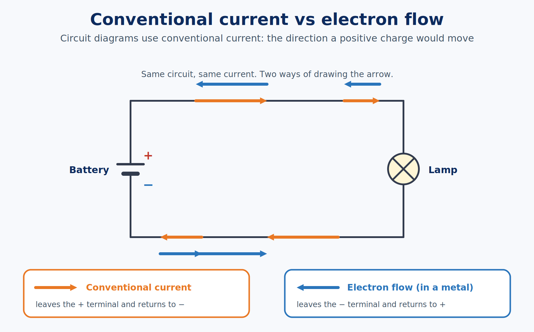
Look at any circuit diagram and the arrows show current leaving the positive terminal of the battery, traveling through the circuit, and returning to the negative terminal. Yet in a metal wire, the electrons are drifting the other way. What gives?
The answer is history. Benjamin Franklin, in the 1700s, had to guess which kind of charge was moving, and he guessed that positive charge flows. He had no way to know. Electrons weren't discovered until 1897, long after the convention was baked into the field. By then, the math, the textbooks, and the symbols all assumed positive charge was the thing moving.
The result is called conventional current: the direction a positive charge would move. In a simple battery circuit, it flows from the positive terminal, through the load, and back to the negative terminal. Electron motion in a metal runs opposite. This is not an error that needs fixing. Every circuit symbol, every datasheet, and every textbook uses conventional current, and the physics works out identically either way as long as you stay consistent. In this series I'll use conventional current for all circuit discussions and tell you whenever I mean electron motion.
Let me pull the pieces together. Current is charge per second, one coulomb per second is one amp, the carriers drift slowly, and diagrams draw the flow opposite to the electrons on purpose. Now for what has to be true for any of it to happen at all.
Why Current Needs a Complete Loop
A steady current needs two things. First, a complete conducting path, an unbroken loop from the source, through the load (the part doing the work, such as a lamp or LED), and back to the source. Second, a source that keeps pushing, the voltage we covered in How Voltage Works.
Open the loop and the current stops everywhere in that loop, almost instantly. A switch doesn't "use up" current. It simply opens or closes the path.
Which brings up a common mistake: the idea that current gets used up as it travels through a lamp. It doesn't. Charge is conserved, meaning it is neither created nor destroyed. The same amount of charge that goes into the lamp comes out the other side. What the lamp takes is energy, which it turns into light and heat. In a simple single-loop circuit, the current is the same at every point along the loop. (When the path splits into branches, the current divides and then recombines, a topic for How Kirchhoff's Circuit Laws Work.)
Understanding the loop also keeps your meter alive, because it tells you where the meter has to go.
Measuring Current Safely
An ammeter (or a multimeter set to measure amps) counts charge passing through a path, so it has to become part of that path. You break the circuit open and insert the meter so all of the current flows through it. Electricians call this connecting the meter in series, meaning one after another in a single line. That is the opposite of how you connect a voltmeter, which goes across a part.
There is a reason for the care. A meter's current input has extremely low resistance, because it must not disturb the circuit it is measuring. If you connect that input straight across a battery, you have made a near short circuit, a connection that lets a huge current flow with nothing to limit it. It can blow the meter's internal fuse, damage the battery or leads, and make things hot.
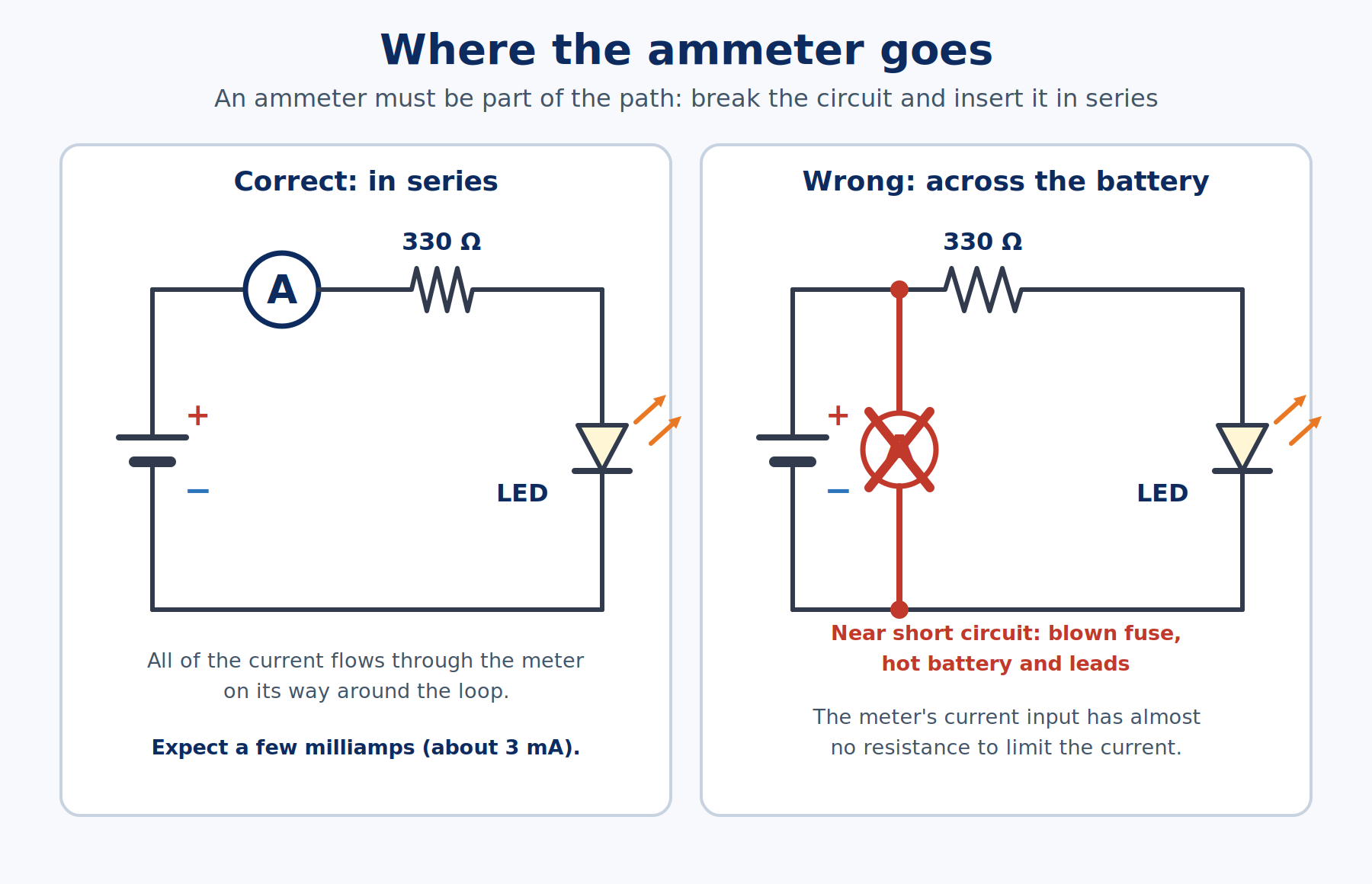
The safe routine for low-voltage circuits goes like this:
- Use a low-voltage source with a current-limiting part. A pair of AA cells (about 3 V) in series with an LED and a 330 Ω resistor is a good example. A resistor in series like this limits the current to a few milliamps. I'll show you how to calculate that in How Ohm's Law Works, so for now just trust the setup.
- Plan before you power up. Know roughly what current to expect and make sure it is below the rating of every part, including your meter.
- Move the red lead into the current jack. Many meters have a mA jack and a separate, higher-range A jack. Start with the higher-range one if you don't know the current yet. The black lead stays in COM.
- Break the circuit, then insert the meter. Disconnect one wire in the loop and let the meter bridge the gap. Don't move a lead while the circuit is powered.
- Read the value. For the LED example you should see a few milliamps.
- Put the red lead back in the voltage jack when you're done. This is the mistake that blows fuses later, when you next try to measure voltage with the lead still sitting in the current jack.
Never try to measure the current of a wall outlet by putting probes into it. That is a dangerous mistake, and nothing in this article covers AC line current. If you don't have a meter handy, the Circuit Lab section below lets you read a simulated circuit's current with no risk to anything.
Try Current in the Circuit Lab
This is the LED loop from the measuring section with one addition, a switch, so you can open and close the loop yourself. A 3 V supply pushes current through the switch, a 330 Ω resistor, and a red LED, one after another. Watch whether the same current shows up in every part, and what happens the moment the loop is broken.
For readers who aren't running it: with the switch closed, the supply, switch, resistor, and LED form one complete ring, the LED glows, and about 3.7 mA (thousandths of an amp) flows. The LED keeps about 1.8 V for itself and the resistor takes the other 1.2 V. With the switch open, there is a gap in the ring and no current flows.
The Circuit Lab circuit is connected like this:
| Net | Connects | Why |
|---|---|---|
| SUPPLY | Supply + and the switch's pin 1 | Where the current leaves the supply |
| AFTER_SWITCH | The switch's pin 2 and R1 pin 1 | Passes current on only while the switch is closed |
| MIDDLE | R1 pin 2 and the LED's anode (A) | Links the resistor to the LED so one current passes through both |
| GROUND | The LED's cathode (K) and supply − | The return path that closes the loop |
The supply is set to 3 V, R1 is 330 Ω, D1 is a red LED, and the switch starts closed.
Using the Circuit Lab
- Run, the green button in the toolbar, starts the simulation. Reset at the top right puts the circuit back the way it started (it asks you to confirm first).
- The multimeter is the meter icon in the toolbar. To move a probe, click the Red or Black button on the meter, then click a part's lead or a hole on the desk. The reading is the red probe's point minus the black probe's point, so swapping the probes flips the sign. In this lab the meter opens already connected. Drag the meter by its title bar (the word Multimeter) to move it, so it does not sit on top of the circuit, and use the × to close it.
- Zoom by holding Ctrl (Command on a Mac) and turning the mouse wheel over the desk. Turning the wheel without a key pans the desk instead.
- Open full workbench, at the top right, opens the same circuit on its own page, where you can add parts and wires.
To use the switched LED loop, follow these steps:
- Press Run. The LED should glow.
- The multimeter is already open in A DC (DC amps) mode, with its probes on the two ends of R1. It should read about 3.7 mA, the current through the resistor.
- Move both probes onto the LED's two leads (click the Red or Black button, then the lead). The reading is the same, because it is the same current.
- Click the switch to open it. The LED goes dark and the meter's display drops to a dash, which is how the meter says there is no current path. The supply is still connected, but without a complete loop nothing flows. Click the switch again to close the loop.
One difference from a bench is worth knowing. A real ammeter has to be wired into the loop, as the measuring steps earlier in this article describe. The simulated meter reads a part's current without breaking the circuit.
So the loop carried one number, about 3.7 mA, wherever you looked, and none at all when it was open.
A short history of the ampere
In 1820, Hans Christian Ørsted noticed that a wire carrying a current made a nearby compass needle swing. That was the first link between electricity and magnetism. André-Marie Ampère heard about it and within weeks had begun a series of experiments showing that wires carrying current attract and repel each other, laying the foundation of electrodynamics. The unit of current honors him. For most of the 20th century the ampere was defined by the force between two long parallel wires. In 2019 the definition was changed so that it is fixed by the exact value of the elementary charge, 1.602176634 × 10⁻¹⁹ coulombs. The practical meaning didn't change: one amp is still one coulomb per second.
Common Misconceptions
- "Current gets used up." Charge is conserved. A load takes energy from the circuit, not the charge itself.
- "Electrons travel from the battery to the lamp at nearly the speed of light." Individual electrons drift slowly. The electric field, and the energy it carries, spreads much faster.
- "Current and voltage are two names for the same thing." Voltage is potential difference. Current is the rate of charge flow. They are different quantities.
- "Current is always electrons." Ions, holes, and other charged particles can carry current too.
- "An ammeter goes across a part, like a voltmeter." An ammeter goes in series, in a circuit whose current is limited by something other than the meter.
Related articles
- How Voltage Works explains the potential difference that sets charge in motion.
- How Electrical Resistance Works covers what limits how much current flows.
- How Ohm's Law Works connects current to voltage and resistance with one equation.
- How Kirchhoff's Circuit Laws Work shows how current divides and recombines at junctions.
- How Direct Current (DC) Works (coming soon) and How Alternating Current (AC) Works (coming soon) compare current that flows one way with current that reverses.
Wrapping up
Electric current is the rate at which charge passes a point, measured in amps, where one amp is one coulomb per second. In a metal wire, the carriers are electrons drifting very slowly on top of their random motion, while the electric field spreads through the wire far faster. Diagrams use conventional current, which points from positive to negative, opposite the electron drift. Current needs a complete loop to flow, it is the same everywhere in a single-loop circuit, and it is measured with a meter placed in series with a current-limited circuit.
Hack The World and Make Awesome.