How Ohm's Law Works: Mastering Fundamental Electronics Part 04
Suppose you hook a 9 V battery to a small part that wants about 15 milliamps, and you aren't sure what to put in the path to keep it that way. Pick a resistance that is too low and too much current flows, so the part overheats. Pick one that is too high and it barely works. There is no need to guess. One short equation tells you what you need, and it shows up in nearly every circuit calculation.
That equation is Ohm's law. It ties together three things you have already met in this series: voltage, current, and resistance. Learn it once, and you can size a resistor, predict a meter reading, or work out whether a circuit is about to cook something.
In this article I'll show you the equation, how to keep the units straight (where most beginners go wrong), how to solve for each quantity, how to check an answer with power, where the law stops being true, and a simple setup you can use to confirm it with two resistors. If voltage, current, and resistance are new to you, skim How Voltage Works, How Electric Current Works, and How Electrical Resistance Works first. I'll re-define each term briefly here.
The Law Itself
For many materials and components, the voltage across the part is proportional to the current through it. The constant of proportionality is the resistance. Written as an equation:
V = I × R
V is voltage in volts, I is current in amps, and R is resistance in ohms. Notice that this is the same relationship as the definition of resistance from the last article, R = V/I, rearranged. For a part that obeys it, the ratio holds steady no matter what voltage you apply.
You can rearrange the equation to solve for whichever quantity you don't know:
V = I × R
I = V / R
R = V / I
You may have seen a "formula triangle" that helps people remember this. It's fine as a memory aid, but it explains nothing. Understand what each form means: voltage is what you apply, current is what you get, and resistance is what sets the ratio between them.
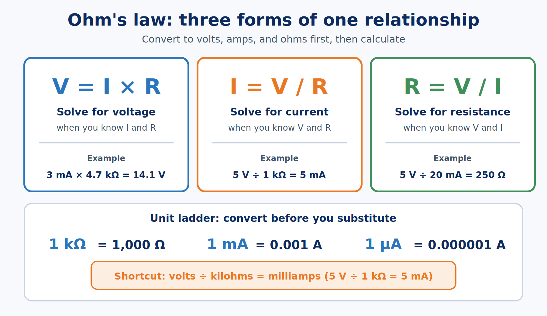
The equation itself is short. Where people go wrong is the units, so that comes next.
Keeping the Units Straight
Almost every wrong answer comes from mixing units. Ohm's law works in base units: volts, amps, and ohms. Real parts, though, are labeled with prefixes. A prefix is a letter that scales a unit, and you need these three constantly:
| Prefix | Symbol | Means | Example |
|---|---|---|---|
| kilo | k | × 1,000 | 4.7 kΩ = 4,700 Ω |
| milli | m | ÷ 1,000 | 15 mA = 0.015 A |
| micro | µ | ÷ 1,000,000 | 250 µA = 0.00025 A |
Convert to base units before you substitute, then convert back to something readable at the end. For the first worked example, put 5 V across a 1 kΩ resistor:
I = V / R = 5 V / 1,000 Ω = 0.005 A = 5 mA
Watch the units cancel: volts divided by ohms gives amps, since 1 Ω is defined as 1 V per A. If your answer has the wrong unit, the setup is wrong. (There is a shortcut that avoids conversion entirely: volts divided by kilohms gives milliamps. So 5 V / 1 kΩ = 5 mA.)
Two more examples with the other two forms:
- Finding resistance. A 5 V source pushes 20 mA through an unknown part. R = V / I = 5 V / 0.020 A = 250 Ω.
- Finding voltage. A current of 3 mA flows through a 4.7 kΩ resistor. V = I × R = 0.003 A × 4,700 Ω = 14.1 V across it.
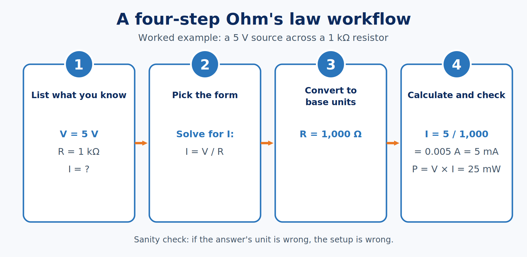
With the units sorted, we can put the law to work on the problem from the start of this article.
Picking a Resistor
Now back to the opening problem. You have a 9 V source and you want about 15 mA. Solve for resistance:
R = V / I = 9 V / 0.015 A = 600 Ω
That 600 Ω is the ideal answer, but resistors are only sold in certain standard values. A common 5 percent series includes 560 Ω and 620 Ω, and 600 Ω isn't one of them. Pick 620 Ω, the nearest standard value that keeps current at or just under your target, and recheck:
I = 9 V / 620 Ω ≈ 14.5 mA
Close enough. Now check that the resistor can survive. Resistance turns electrical energy into heat, and the rate is power, measured in watts (W). Power comes from multiplying voltage by current, and you can restate it using Ohm's law in three equivalent ways:
P = V × I = I² × R = V² / R
For the 620 Ω resistor across 9 V, P = 9² / 620 = 81 / 620 ≈ 0.13 W, or 130 milliwatts. A standard small resistor is rated for 0.25 W (a quarter watt), so this one would be running at about half its rating. That is a reasonable margin, but I'd want more headroom if the resistor will sit in a warm enclosure. (Component ratings and safety margins are covered in How Electronic Component Derating Works (coming soon).)
Notice also that the 5 percent tolerance on a 620 Ω part means the real value could land anywhere from about 589 to 651 Ω, which moves your current between roughly 13.8 and 15.3 mA. Ohm's law gives the exact answer for the exact resistance. Real parts give you a range around it.
You can use power as a cross-check on any Ohm's law answer. For the earlier 5 V and 1 kΩ example: P = V × I = 5 V × 5 mA = 25 mW, and P = I² × R = (0.005)² × 1,000 = 25 mW, and P = V² / R = 25 / 1,000 = 25 mW. When all three forms agree, your arithmetic is solid.
To recap: V = I × R, three forms, base units first, and power as a cross-check. All of that assumes the part behaves like a resistor, and plenty of parts do not.
Where Ohm's Law Stops Working
Ohm's law is an empirical relationship, which means it came from measurement and describes how certain materials behave, not a rule every component must follow. A part that obeys it is called ohmic.
If you plot current against voltage for an ohmic resistor, you get a straight line through zero. The slope of that line is the reciprocal of the resistance (1/R), so a lower resistance makes a steeper line. For a 1 kΩ resistor the line climbs 1 mA for every volt. For a 2.2 kΩ resistor it climbs about 0.45 mA per volt.
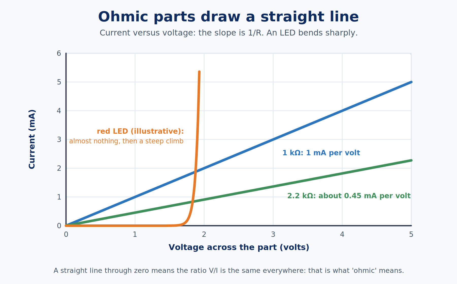
An LED, shown as the bent curve, is a very different animal. It passes almost nothing until the voltage reaches a threshold of roughly 1.6 to 2 V (depending on color), and then current climbs steeply. You can calculate V / I at any single point on that curve, but the answer changes from point to point, so it isn't "the" resistance of the LED. The same applies to a filament lamp, a thermistor, and most semiconductor devices. Even a plain resistor drifts a little as it self-heats.
Dividing any voltage by any current gives you a number in ohms. That number is only a true constant for an ohmic part under stable conditions. Remember this next time a quick V/I division gives you a strange answer.
If you ever read about the microscopic form of the law, J = σE (current density equals conductivity times electric field), that is the same idea at the level of the material. For circuit work, V = IR is the one you'll use.
Knowing the limits, you can now test the law on a part that should obey it.
Checking It with a Real Measurement
If you have a breadboard, a meter, and a 5 V source that can't supply much current (a USB power source through a breakout is fine), here is a safe way to confirm Ohm's law.
- Measure each resistor out of the circuit first. Use the ohms setting with no power connected. Say you have a 1 kΩ and a 2.2 kΩ part. Write down what the meter says. It will probably be off by a few percent.
- Predict the current for each resistor from your measured value and the 5 V source.
- Measure the source voltage with the meter in parallel (across the supply).
- Measure the current by breaking the loop and inserting the meter in series, with the red lead in the current jack. Don't move a lead between jacks while the circuit is powered, and move the lead back to the voltage jack afterward.
- Compare your prediction and your measurement.
| Resistor | Predicted current at 5 V | Range for 5% parts | Power in resistor |
|---|---|---|---|
| 1 kΩ | 5.0 mA | 4.8 to 5.3 mA | 25 mW |
| 2.2 kΩ | 2.3 mA | 2.2 to 2.4 mA | 11 mW |
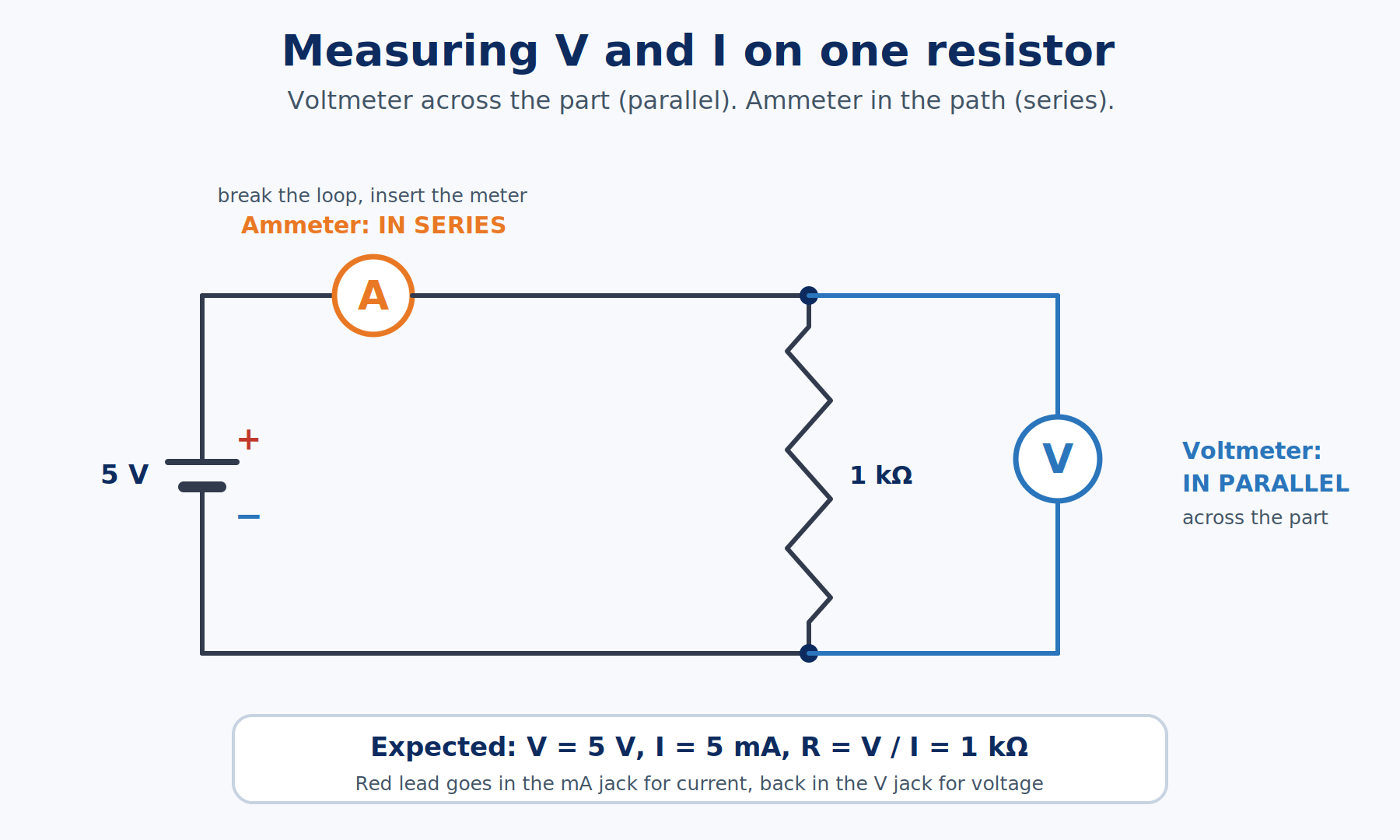
If your results land in those ranges, the law is working. If they're far off, look for a lead in the wrong jack, a loose breadboard connection, or a source that is sagging under load. If you don't have the gear, the Circuit Lab section below lets you do the same check with virtual meters.
Try Ohm's Law in the Circuit Lab
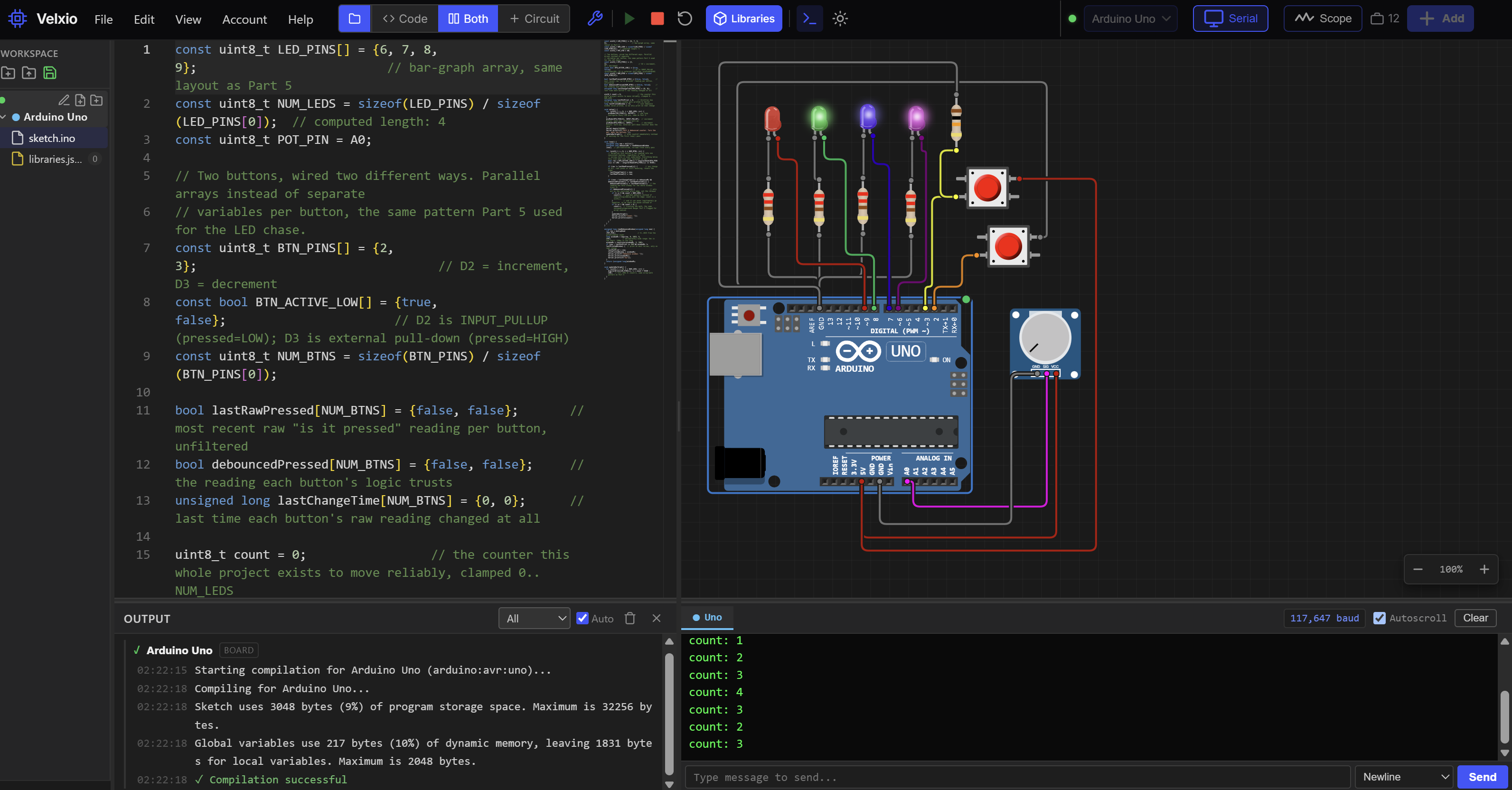
This is the resistor check from the section above, with a variable resistor so you can change R and watch the current respond. Two separate loops share one 5 V supply, so each sees the full 5 V. One loop has a 1 kΩ fixed resistor. The other has a potentiometer (a resistor with a knob, set in its Properties card) at 5 kΩ. Check that the current in each loop matches voltage divided by resistance, and that a bigger resistance gives a smaller current at the same voltage.
For readers who aren't running it: the 1 kΩ resistor carries 5 V ÷ 1,000 Ω = 5 mA, and the 5 kΩ pot carries 5 V ÷ 5,000 Ω = 1 mA (thousandths of an amp). Turning the pot to 2.5 kΩ doubles that current to 2 mA, and 2.2 kΩ gives about 2.27 mA, the same as the 2.2 kΩ resistor in the table above. The simulated parts are exact, so there is no tolerance error the way real resistors have.
The Circuit Lab circuit is connected like this:
| Net | Connects | Why |
|---|---|---|
| FIXED_TOP | R1 pin 1 and supply + | Puts the full 5 V on the 1 kΩ resistor |
| FIXED_BOTTOM | R1 pin 2 and supply − | Returns that loop's current |
| POT_TOP | The pot's pin 1 and supply + | Puts the full 5 V on the pot |
| POT_BOTTOM | The pot's wiper (pin 2), pin 3, and supply − | Uses the pot as a two-terminal variable resistor |
The supply is set to 5 V, R1 is 1 kΩ, and the pot is 10 kΩ at 50 percent, which makes 5 kΩ.
Using the Circuit Lab
- Run, the green button in the toolbar, starts the simulation. Reset at the top right puts the circuit back the way it started (it asks you to confirm first).
- Right-click a part and choose Properties… to change a value, such as the pot's position.
- The multimeter is the meter icon in the toolbar. To move a probe, click the Red or Black button on the meter, then click a part's lead or a hole on the desk. The reading is the red probe's point minus the black probe's point, so swapping the probes flips the sign. In this lab the meter opens already connected. Drag the meter by its title bar (the word Multimeter) to move it, so it does not sit on top of the circuit, and use the × to close it.
- Zoom by holding Ctrl (Command on a Mac) and turning the mouse wheel over the desk. Turning the wheel without a key pans the desk instead.
- Open full workbench, at the top right, opens the same circuit on its own page, where you can add parts and wires.
To use the resistor and pot circuit, follow these steps:
- Press Run.
- The multimeter is already open in A DC (DC amps) mode, with its probes on the two ends of R1. It should read about 5 mA, which is 5 V ÷ 1,000 Ω.
- Move both probes to the pot's two ends (pin 1 and the wiper, pin 2). You should read about 1 mA, which is 5 V ÷ 5,000 Ω.
- Right-click the pot, choose Properties…, and set the position to 25, which is 2.5 kΩ. The current should double to about 2 mA, which is 5 V ÷ 2,500 Ω. If the circuit is running, stop it before you make the change, then press Run again.
- Set the position to 22 for 2.2 kΩ, and the current should read about 2.27 mA. Set it to 100 for 10 kΩ, and it should fall to about 0.5 mA.
Each current landed on the value Ohm's law predicts from the voltage and the resistance, with the voltage fixed at 5 V.
A short history of Ohm's law
Georg Simon Ohm published his findings in 1827 after experiments on conductors with galvanic circuits (circuits driven by early chemical batteries). His results were not well received at the time. Critics thought the work was too mathematical and too tidy for the messy science of electricity, and he struggled professionally for years. The Royal Society recognized him with the Copley Medal in 1841, and the unit of resistance was later named the ohm in his honor.
Common Misconceptions
- "Resistance uses up voltage." Voltage is dropped across the resistance as energy is converted to heat, but voltage is a difference between two points. Nothing gets "used up" the way fuel does.
- "A 2 A supply always pushes 2 A." The rating is a maximum it can supply. The actual current is set by the load, using I = V / R.
- "V = IR works for every component." It describes ohmic parts. Diodes, LEDs, lamps, and thermistors need other tools.
- "The formula triangle explains it." The triangle helps you rearrange. Understanding the relationship is what helps you debug.
- "Any V divided by any I gives the part's resistance." Only a constant ratio over a range of voltages shows ohmic behavior.
Related articles
- How Voltage Works, How Electric Current Works, and How Electrical Resistance Works cover the three quantities in the equation.
- How Electrical Power Works (coming soon) expands on watts and the P = VI family of equations.
- How Series Circuits Work (coming soon) and How Parallel Circuits Work (coming soon) apply Ohm's law to several parts at once.
- How Voltage Dividers Work (coming soon) uses Ohm's law to build a very common circuit.
- How Kirchhoff's Circuit Laws Work gives you rules for circuits too complicated for Ohm's law alone.
Wrapping up
Ohm's law says that for an ohmic part, voltage equals current times resistance: V = I × R, with I = V / R and R = V / I as the other two forms. Convert to volts, amps, and ohms before you calculate, and cross-check with power using P = V × I = I² × R = V² / R. It is an empirical rule with limits: resistors obey it closely, while LEDs, lamps, and thermistors do not. Use it to choose a resistor, predict a reading, and then confirm it with a meter or a simulator.
Hack The World and Make Awesome.