How Kirchhoff's Circuit Laws Work: Mastering Fundamental Electronics Part 05
Think about a four-way intersection with no parking lot, no driveway, and no gas station. Cars arrive from several directions and cars leave in several directions. If 10 cars per minute roll in from the north and 6 per minute from the west, then 16 cars per minute have to roll out somewhere. They can't pile up in the middle, and they can't vanish. That is the first idea in this article.
Now imagine a hiking trail that loops back to the trailhead. As you walk the loop you climb some hills and descend others. When you get back to the start, your total gain in elevation and total loss have to cancel, because you are standing at the same height you started. That is the second idea.
Those two commonsense rules, written down for circuits by Gustav Kirchhoff in the 1840s, let you analyze circuits that Ohm's law alone can't handle. In this article I'll define the vocabulary, show you both laws, explain the sign conventions that keep the algebra straight, and solve a complete two-loop circuit by hand, with every number checked two ways. It helps to know How Ohm's Law Works first, since we'll use it as a tool. I'll define everything else as we go.
Nodes, Branches, and Loops
Three words describe the layout of any circuit.
- A node is a point where two or more parts connect. Everything joined by plain wire counts as one node, no matter how long the wire is.
- A branch is a single path between two nodes that carries one current. It might hold one part or several in a row.
- A loop is any closed path you can trace through the circuit that starts and ends at the same place without crossing itself.
People also use the term essential node for a node where three or more branches meet. Those are the junctions that matter for current bookkeeping.
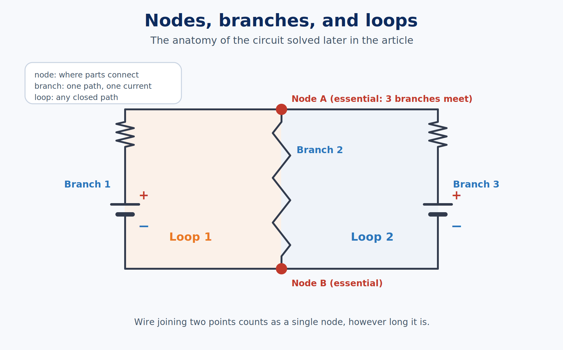
Those three words are enough to state both laws.
The Current Law
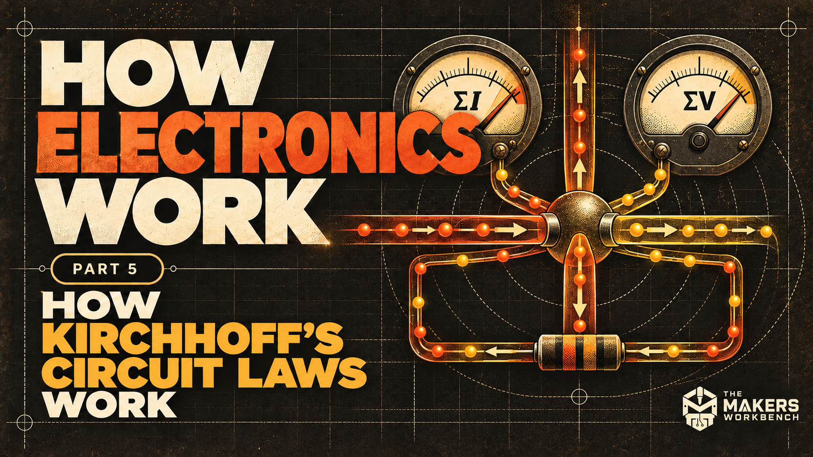
Kirchhoff's current law (KCL) says that at any node, the currents flowing in add up to the currents flowing out. It follows from conservation of charge: charge doesn't pile up at a junction and doesn't appear from nowhere. Written as a sum, with currents flowing into the node counted as positive and currents flowing out counted as negative:
ΣI = 0
The Greek letter Σ (sigma) means "add up all of these." So if 4 mA flows into a node on one wire and 1 mA flows in on another, 5 mA must flow out. That is the intersection with cars, only the cars are charge.
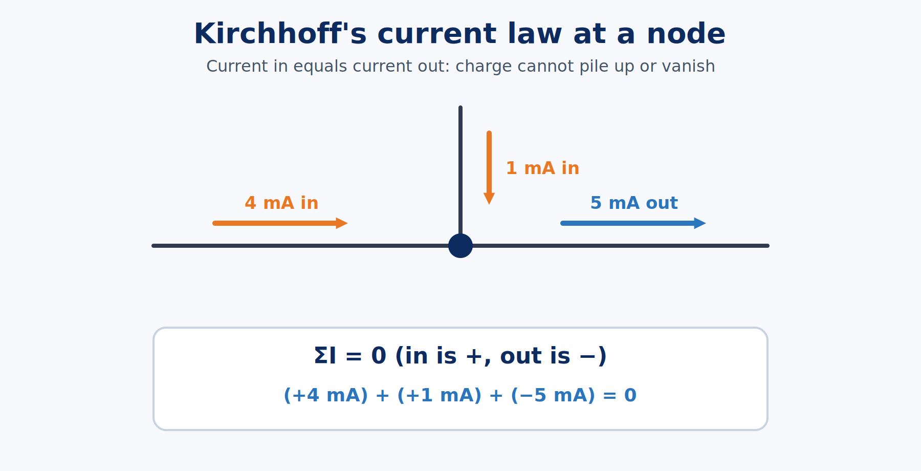
That was the intersection. Now for the hiking trail.
The Voltage Law
Kirchhoff's voltage law (KVL) says that if you walk all the way around any closed loop and add up every voltage rise and drop along the way, the total is zero. It follows from conservation of energy: a charge that returns to its starting point can't have gained or lost net energy from the electric field. In symbols:
ΣΔV = 0
If a battery lifts you up by 10 V, then the parts around the loop have to bring you down by a total of 10 V. This is the hiking loop. The "elevation" is voltage, as we saw in How Voltage Works.
Both laws are easy to say out loud. The trouble starts when you write them as equations, because every term needs the right sign.
Sign Conventions
This is where most mistakes happen, so I'll give you one simple convention and stick to it.
For currents: you are allowed to guess a direction for each branch current. It doesn't need to be right. If your guess is wrong, the math will give you a negative number, and that negative number tells you the true flow is opposite your arrow. Nothing has gone wrong.
For voltages: pick a direction to travel around the loop, then use these rules as you pass each part.
| Traversing... | Sign to write |
|---|---|
| a source from its − terminal to its + terminal | +E (a rise) |
| a source from its + terminal to its − terminal | −E (a drop) |
| a resistor in the same direction as your assumed current | −I × R (a drop) |
| a resistor against your assumed current | +I × R (a rise) |
Write the signs as you walk, one part at a time, and set the total equal to zero. A common slip is to add up every voltage as a plain positive number. They are signed changes. Some go up and some go down.
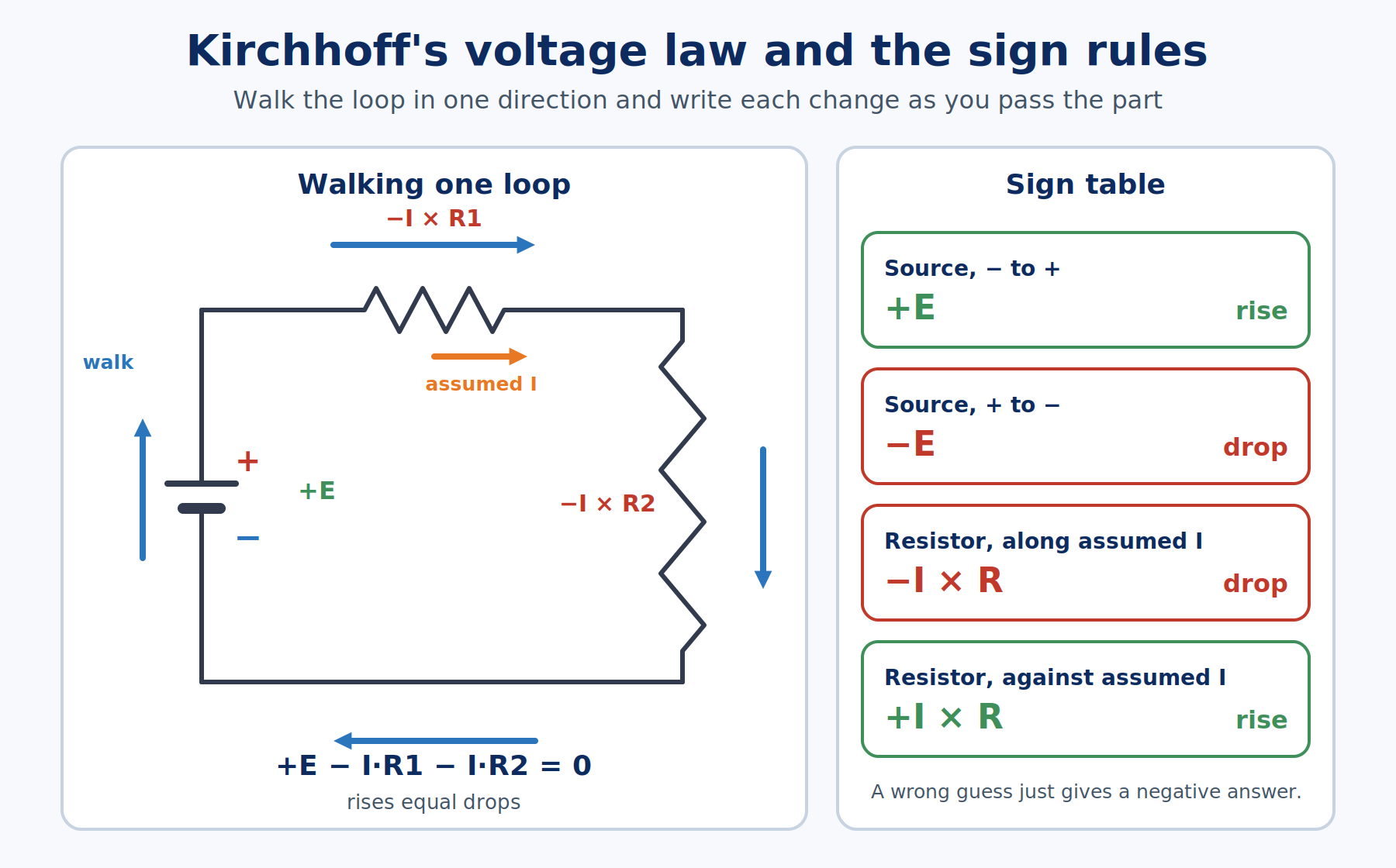
Where things stand: the current law handles nodes, the voltage law handles loops, and one consistent sign rule keeps the algebra honest. One question is left before a full example, which is how many equations you need.
Counting Equations
You need as many independent equations as you have unknown currents, and no more. A fresh equation only counts if it adds information. For a circuit with N essential nodes, KCL gives you N − 1 independent equations, because the last node's equation is just a repeat of the others. For loops, you need enough independent loops that each branch is covered at least once.
Our example below has three unknown currents. It has two essential nodes, so KCL gives 1 independent equation. Two independent loops give 2 more. One plus two is three equations for three unknowns, so we can solve it. A third loop around the outside would be a legitimate equation, but it wouldn't tell us anything the others hadn't. We'll use it later as a check.
With the rules and the count settled, here is a circuit to solve from start to finish.
A Worked Two-Loop Example
The circuit has three branches that join at a top node, A, and a bottom node, B. We'll call B our 0 V reference.
- Left branch: a 9 V source (E1) in series with R1 = 1 kΩ
- Middle branch: R2 = 3 kΩ
- Right branch: a 5 V source (E2) in series with R3 = 1 kΩ
Both sources have their + terminals toward the top. We'll assume I1 flows up the left branch into node A, I2 flows down the middle branch from A to B, and I3 flows up the right branch into node A.
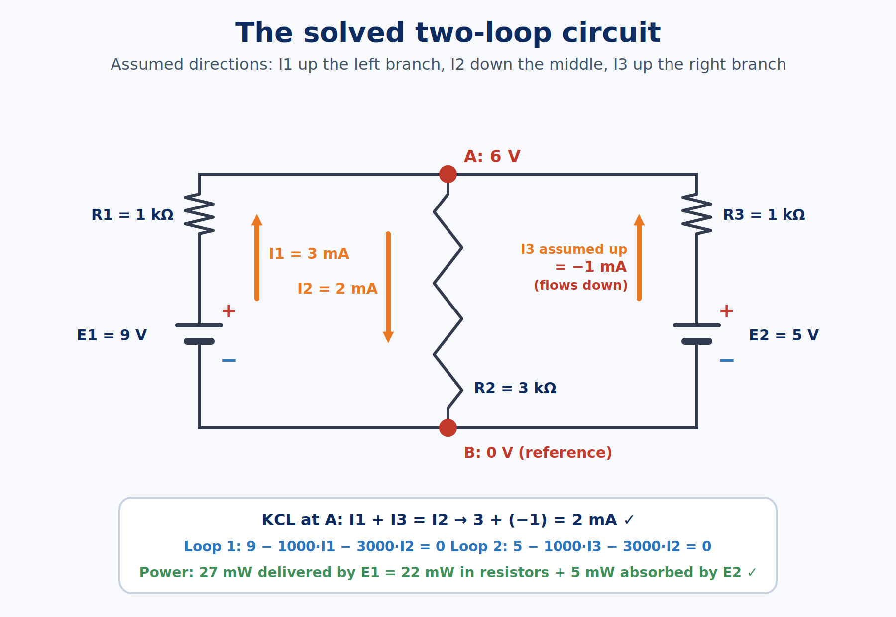
Step 1: KCL at node A. Currents I1 and I3 flow in, and I2 flows out:
I1 + I3 = I2
Step 2: KVL around the left loop (E1, R1, R2). Start at B and go up through the source, then through R1 (with I1), then down through R2 (with I2):
+9 − (1,000)(I1) − (3,000)(I2) = 0
Step 3: KVL around the right loop (E2, R3, R2), same idea:
+5 − (1,000)(I3) − (3,000)(I2) = 0
Step 4: Substitute I2 = I1 + I3 into both loop equations and tidy up. Working in milliamps with kΩ keeps the numbers small:
4 × I1 + 3 × I3 = 9
3 × I1 + 4 × I3 = 5
Step 5: Solve. Multiply the first equation by 4 and the second by 3, which gives 16 × I1 + 12 × I3 = 36 and 9 × I1 + 12 × I3 = 15. Subtracting the second from the first leaves 7 × I1 = 21, so I1 = 3 mA. Put that back into the first equation: 4(3) + 3 × I3 = 9, which gives 3 × I3 = −3, so I3 = −1 mA. Then I2 = I1 + I3 = 2 mA.
The negative sign on I3 is the lesson. Our guess was that I3 flows up through the right branch. It flows downward: 1 mA is pushed backward through the 5 V source, which means that source is being charged by the 9 V source rather than supplying energy. That is how a battery behaves while charging.
Solving it is only half the job.
Checking the Answer
Never trust an answer you haven't verified. Three independent checks follow.
KCL at node A: 3 mA + (−1 mA) = 2 mA ✓
KVL around the outside loop (not used in the solution): start at B, go up through E1 (+9), down through R1 along I1 (−3 V), then down the right side through R3 against the assumed direction of I3 (+I3 × R3 = −1 V), then down through E2 from + to − (−5 V). Total: 9 − 3 − 1 − 5 = 0 ✓
Power balance. Energy has to add up too. Resistor power is I² × R: R1 dissipates (3 mA)² × 1 kΩ = 9 mW, R2 dissipates (2 mA)² × 3 kΩ = 12 mW, and R3 dissipates (1 mA)² × 1 kΩ = 1 mW. That totals 22 mW. Source E1 delivers 9 V × 3 mA = 27 mW. The remaining 5 mW goes into E2 (5 V × 1 mA), which is absorbing it. Delivered 27 mW equals 22 mW dissipated plus 5 mW absorbed ✓
Those checks all happen on paper. A real or simulated circuit is the independent test.
Confirming It on a Breadboard or in a Simulator
If you have two adjustable supplies (or a dual-output bench supply), set them to 9 V and 5 V, join their negative terminals as the common reference, and build the circuit with the resistor values above. Instead of breaking the circuit repeatedly to insert an ammeter, measure each node voltage relative to the shared reference with a voltmeter, then work out the currents from the resistor voltages using Ohm's law. That is less invasive and safer for your meter.
| What to measure | Expected |
|---|---|
| Voltage at node A relative to B | about 6.0 V |
| Voltage across R1 (E1 side minus node A) | about 3.0 V, giving 3 mA |
| Voltage across R2 | about 6.0 V, giving 2 mA |
| Voltage across R3 (node A minus E2 side) | about 1.0 V, giving 1 mA toward E2 |
Real resistors have a tolerance of a few percent, so expect readings within a few percent of these. If you don't have hardware, the Circuit Lab section below builds this circuit with the same values, and you can read every voltage and current on it.
Try the Two-Source Circuit in the Circuit Lab
You don't need two bench supplies to check the worked example, because the Circuit Lab has them built in. This circuit has a 9 V source and a 5 V source feeding one junction through R1 and R3, with R2 running from the junction to ground. Three things are worth checking: the junction sits at 6 V, the currents entering it equal the currents leaving it, and R3's current runs backward into the 5 V source.
If you can't run it: the three branches meet at one junction, and 3 mA arrives through R1 while 2 mA leaves through R2 and 1 mA leaves through R3 toward the 5 V source. The numbers are the same as the ones solved above.
The Circuit Lab circuit is connected like this:
| Net | Connects | Why |
|---|---|---|
| E1_PLUS | R1 pin 1 and the 9 V supply + | Starts the left branch at 9 V |
| JUNCTION | R1 pin 2, R2 pin 1, and R3 pin 1 | Node A, where the three branches meet |
| E2_PLUS | R3 pin 2 and the 5 V supply + | Ends the right branch at 5 V |
| COMMON | R2 pin 2 and both supplies' − | Node B, the shared 0 V reference |
E1 is 9 V, E2 is 5 V, R1 and R3 are 1 kΩ, and R2 is 3 kΩ.
Using the Circuit Lab
- Run, the green button in the toolbar, starts the simulation. Reset at the top right puts the circuit back the way it started (it asks you to confirm first).
- The multimeter is the meter icon in the toolbar. To move a probe, click the Red or Black button on the meter, then click a part's lead or a hole on the desk. The reading is the red probe's point minus the black probe's point, so swapping the probes flips the sign. In this lab the meter opens already connected. Drag the meter by its title bar (the word Multimeter) to move it, so it does not sit on top of the circuit, and use the × to close it.
- Zoom by holding Ctrl (Command on a Mac) and turning the mouse wheel over the desk. Turning the wheel without a key pans the desk instead.
- Open full workbench, at the top right, opens the same circuit on its own page, where you can add parts and wires.
To use the two-source circuit, follow these steps:
- Press Run.
- The multimeter is already open in V DC mode, with the red probe on the junction and the black probe on the common ground end of R2. It should read about 6 V.
- Move the probes across each resistor in turn. R1 should read about 3 V, R2 about 6 V, and R3 about 1 V.
- Switch the meter to A DC and put the probes on the two ends of each resistor in turn. You should see about 3 mA, 2 mA, and 1 mA (the meter shows R3's as 1,000 µA, and its voltage as 1,000 mV).
- Check the laws yourself: 3 mA in equals 2 mA plus 1 mA out (the current law), and 9 − 3 − 1 − 5 = 0 around the outside loop (the voltage law).
The junction sat at 6 V and the three currents split 3, 2, and 1. The 5 V supply box on the desk reads 0 mA, so use the meter for that branch. The meter shows the size of R3's current, 1,000 µA, whichever way round the probes are. The negative sign in the worked example is the on-paper way of saying that current runs backward through E2.
Where the Laws Stop Working
Kirchhoff's laws are exact under the lumped-element approximation, which treats each part as a point and each wire as a perfect connection with no delay. That is an excellent assumption for ordinary circuits. At very high frequencies, or in physically large structures, signals take noticeable time to travel and changing magnetic fields can induce voltages that KVL doesn't count. Those cases need fuller electromagnetic treatment. For the circuits in this series, you can use the laws with confidence.
A short history of the laws
Gustav Kirchhoff was a German physicist who formulated these rules in the 1840s, when he was in his early twenties. He built on Ohm's work and extended it to networks with many branches. The laws were so useful that they've remained a cornerstone of circuit analysis for nearly two centuries.
Common Misconceptions
- "I need to guess the current direction correctly." You don't. A wrong guess just returns a negative number.
- "A loop has to follow the path of one particular current." A loop is any closed path through the circuit, regardless of which currents flow along it.
- "Voltage drops are all positive numbers I can add." They are signed changes, and the signs matter.
- "More equations are always better." Only independent equations add information. Extra ones are useful as checks.
Related articles
- How Ohm's Law Works is the tool you'll use inside every Kirchhoff problem.
- How Series Circuits Work (coming soon) and How Parallel Circuits Work (coming soon) are special cases that fall out of these laws.
- How Voltage Dividers Work (coming soon) and How Current Dividers Work (coming soon) turn the laws into everyday design tools.
- How Electrical Ground Works (coming soon) explains the reference node we chose as 0 V.
Wrapping up
Kirchhoff's current law says the currents at a node sum to zero, which comes from conservation of charge. His voltage law says the voltage changes around any closed loop sum to zero, which comes from conservation of energy. Choose a direction for each current, write signed equations as you walk each loop, and use one independent equation per unknown. A negative answer just means your arrow pointed the wrong way. Check every result with KCL at a node, KVL around an unused loop, and a power balance.
Hack The World and Make Awesome.