How Open and Closed Circuits Work: Mastering Fundamental Electronics Part 11
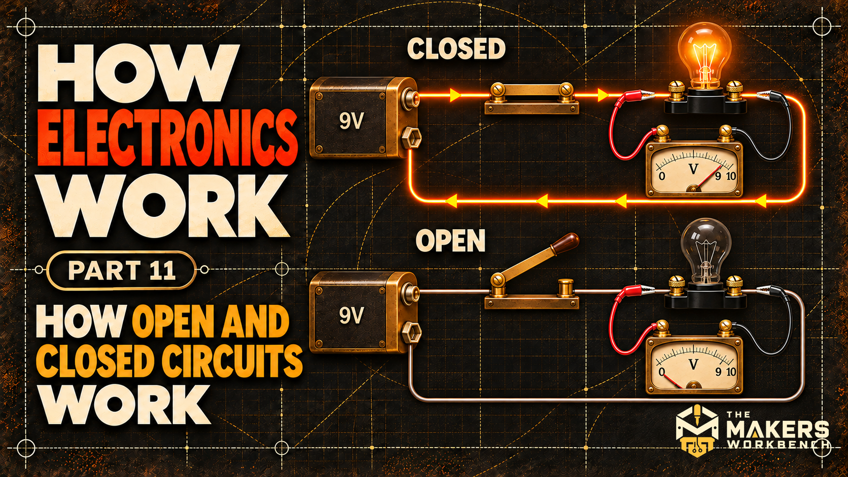
Connect a battery to a lamp through a switch, and the switch decides whether the lamp lights. With the switch closed, current leaves the battery's positive terminal, passes through the lamp, and returns to the negative terminal, and the lamp glows. With the switch open, the path has a gap in it, no current flows anywhere in the loop, and the lamp stays dark.
A circuit whose path is unbroken from the source, through the loads, and back to the source is a closed circuit. A circuit with a break anywhere in that path is an open circuit. Steady current flows only in a closed circuit [1][2]. A switch is a part built to open and close the path on purpose, so a person or a control circuit decides when the path exists.
Open circuits matter because they are the most common reason a project does nothing when power is applied: a broken connection or a loose wire is the most likely cause. The same idea covers blown fuses, loose connectors, cracked circuit-board traces, and every switch in the off position. An open circuit is not electrically dead, either. The break carries the voltage that the loop's current would otherwise have used up, and measuring that voltage is how a break gets found.
This article builds on How Electrical Ground Works, which defined the reference point that voltages are measured from, and on How Voltage Works, How Electric Current Works, How Electrical Resistance Works, and How Kirchhoff's Circuit Laws Work. It explains why a break anywhere stops the current, what voltage appears across a break, and how real switches depart from the ideal. It also covers why opening a coil can strike an arc, the common accidental breaks, and how to find a break with a meter.
Every circuit here runs from a 9V battery, and none involves line power. The first circuit includes a light-emitting diode (LED), a part that lights when current passes through it in one direction, before its own article explains how it works. Here it serves only as an indicator.
A Circuit Is a Complete Loop
For current to flow through a part, there has to be a complete path from the positive terminal of the source, through the part, and back to the negative terminal [1]. A circuit is an unbroken loop of conductive material [3]. The wires in a schematic are drawn as perfect conductors. Real wires are not perfect, but they come close enough for the model [2].
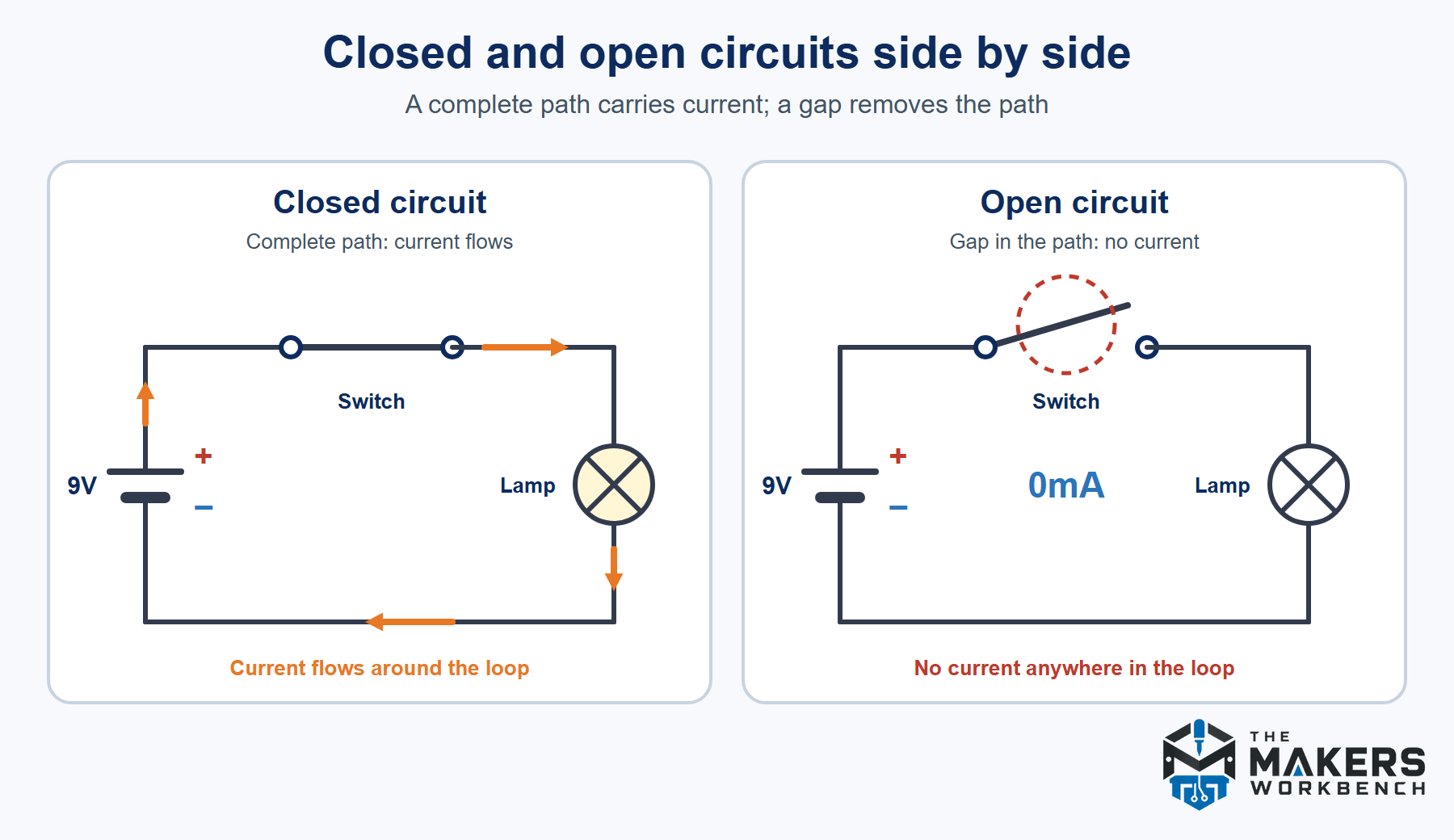
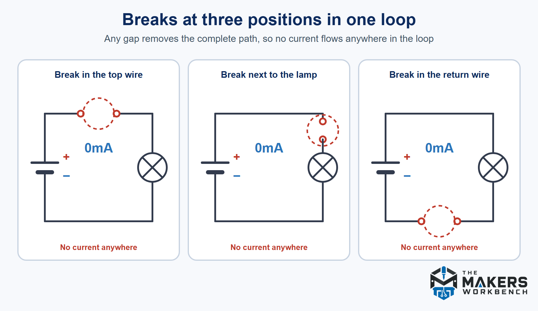
A ring of water pipe makes the idea concrete. Fill a closed ring with water and put a pump in one section. If the pump moves 2 liters per second past one point, 2 liters per second pass every other point in the ring. Cut the pipe anywhere, and the flow stops everywhere in the ring, because the water at the cut has nowhere to go. Current behaves the same way: any break anywhere in a loop stops the flow throughout the loop, and the location of the break does not change that [3]. The analogy has a limit. A cut pipe leaks, while a cut wire spills nothing. The charge carriers stay in the metal, and the loop stops carrying current.
Schematics draw current as moving from the positive terminal through the load to the negative terminal. That is the conventional direction, the way positive charge would move. In metals the moving charges are electrons, which travel the opposite way around the loop [2]. Nothing in this article depends on which direction is used.
The loop explains why a gap stops current. It does not say how much current flows when the loop is closed or what voltage appears where, and the ideal switch model answers both.
Closed and Open States
An ideal closed switch has zero resistance, so it passes current with no voltage across it. An ideal open switch has infinite resistance, so no steady current flows. Real switches fall short of both ideals, as a later section shows, but the ideal model is enough to see the pattern.
Take a 9V supply, a switch, a 1kΩ resistor, and a red LED in one loop. The resistor limits the current, because an LED connected straight across a supply can destroy itself by drawing too much. When an LED conducts, it drops a fairly steady voltage across itself, called its forward voltage. One datasheet for a common 5mm red LED, the Vishay TLDR5400, lists 1.8V typical and 2.2V maximum at 20mA [4]. I use 2V here, a round value inside that range, so the arithmetic stays clean.
With the switch closed, the LED takes its 2V and the resistor takes the rest of the supply. The current is that remainder divided by the resistance:
I = (Vsupply − VLED) ÷ R = (9V − 2V) ÷ 1kΩ = 7mA
That is 7 milliamps, or 0.007 amps. The resistor drops 7V (7mA × 1kΩ), the LED drops 2V, and the switch drops 0V. The drops add up to the 9V supply, as Kirchhoff's loop rule requires: 9V − 7V − 2V − 0V = 0V [5]. The resistor converts 49mW of electrical power to heat (7V × 7mA = 49 milliwatts).
With the switch open, the loop has a break, so the current is 0mA and the LED goes dark. The Circuit Lab section below lets you flip the switch and watch both states.
Try a Circuit With an LED and a Switch in the Circuit Lab
The Circuit Lab is the circuit simulator built into this site, so everything in it is a simulation and not real hardware. This circuit is the loop described above. It shows the two states: closed, with the LED lit and about 7mA flowing, and open, with the LED dark and no current. Watch the LED and the small panel beside the supply, which shows the supply's output voltage and current.
For readers who are not running it: a 9V supply, a switch, a 1kΩ resistor, and a red LED sit in a single loop. With the switch closed, the LED glows and the supply panel reads 9V and 7mA. With the switch open, the LED is dark and the panel reads 9V and 0mA.
The Circuit Lab circuit is connected like this:
| Net | Connects | Why |
|---|---|---|
| SUPPLY | Supply positive terminal and switch pin 1 | Brings the positive side of the supply to the switch |
| AFTER_SWITCH | Switch pin 2 and resistor pin 1 | Passes the supply on to the resistor only when the switch is closed |
| LED_FEED | Resistor pin 2 and LED anode (the positive side) | The resistor limits the current entering the LED |
| GROUND | LED cathode (the negative side) and supply negative terminal | Returns the current to the supply |
Part values: supply 9V, resistor 1kΩ, LED red.
- Press Run (the green button in the toolbar). The LED lights and the supply panel reads 7mA.
- Click the switch to open it. The LED goes dark and the panel reads 0mA.
- Click the switch again to close it. Press Reset to return the circuit to its starting state.
- Select Open full workbench to change the resistor value and watch the current change.
Closed, the loop carries 7mA and the LED lights. Open, the current is zero and the LED is dark. The LED is dark, but the supply still provides 9V, and that voltage has to appear somewhere across the loop.
Voltage Across the Break
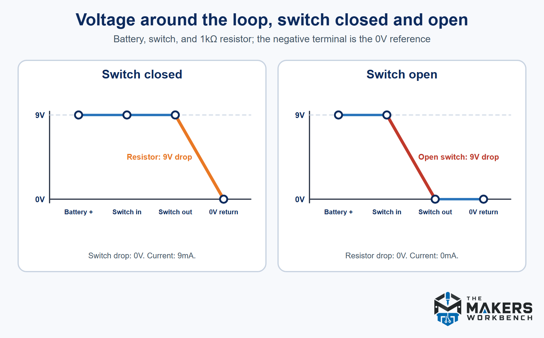
No current does not mean no voltage. In an open circuit, the full supply voltage appears across the break.
The LED's behavior would complicate the arithmetic, so this section uses a simpler loop: the same 9V supply, a switch, and a 1kΩ resistor. With the switch closed, the current is the supply voltage divided by the resistance:
I = V ÷ R = 9V ÷ 1kΩ = 9mA
The resistor drops 9V (9mA × 1kΩ), the switch drops 0V, and the resistor dissipates 81mW (9V × 9mA). Now open the switch. No current can flow, so the resistor's drop is the current times its resistance:
VR = I × R = 0mA × 1kΩ = 0V
Kirchhoff's loop rule says the changes in potential around any closed path add up to zero [5]. Around this loop the supply contributes 9V and the resistor 0V, so the break has to account for the rest:
Vswitch = Vsupply − VR = 9V − 0V = 9V
The same result follows from a physical picture. Voltage is measured between two points, and the negative terminal is the 0V reference, as the previous article described. The wire on the supply side of the open switch sits at 9V. The wire on the far side connects through the resistor to the 0V reference. Because no current flows in the resistor, it drops no voltage, so the far-side wire sits at 0V too. The gap in the switch separates a 9V wire from a 0V wire, which is why the gap carries all 9V.
A closed water tap works the same way. Suppose the water behind a closed tap is under 40psi (pounds per square inch) of pressure, a value chosen for illustration, and the open pipe beyond it is under none. No water moves, and the tap holds the entire 40psi difference. The analogy has a limit: a worn tap drips, while this section treats the switch as ideal. Real switches leak a little too, as a later section shows.
Try a Voltmeter Across an Open Switch in the Circuit Lab
This circuit shows the result above with a meter. A multimeter is already connected across the switch, so you can watch its reading change from 0V when the switch is closed to 9V when it is open.
For readers who are not running it: a 9V supply, a switch, and a 1kΩ resistor sit in a single loop, with a multimeter set to volts across the switch. Closed, 9mA flows, the resistor takes 9V, and the meter reads 0V. Open, no current flows, the resistor takes 0V, and the meter reads 9V.
The Circuit Lab circuit is connected like this:
| Net | Connects | Why |
|---|---|---|
| SUPPLY | Supply positive terminal and switch pin 1 | Brings the positive side of the supply to the switch |
| AFTER_SWITCH | Switch pin 2 and resistor pin 1 | Passes the supply on to the resistor only when the switch is closed |
| GROUND | Resistor pin 2 and supply negative terminal | Returns the current to the supply and sets the 0V reference |
Part values: supply 9V, resistor 1kΩ. The multimeter's red probe is on switch pin 1 and its black probe is on switch pin 2.
- Press Run. The meter is already open and connected across the switch. It reads 0 with a tiny unit prefix (pV, picovolts), which means zero: the Lab's switch is ideal, so the voltage across it is exactly zero.
- Click the switch to open it. The meter reads 9V.
- Click the switch again to close it, and the reading returns to zero. Press Reset to start over.
This circuit has no LED for a reason. If you place the meter across the switch in the first circuit, the meter shows a dash when the switch is open. With the LED dark, nothing gives the wire beyond the switch a voltage the simulator can calculate, while the resistor in this circuit connects that wire to the 0V reference.
Closed, the meter across the switch reads 0V. Open, it reads 9V. The full supply voltage sits across a break.
To recap: steady current needs a complete loop, a break anywhere in the loop stops it everywhere, an ideal closed switch drops 0V, and an ideal open switch carries the whole supply voltage with no current. Real switches depart from both ideals, and the numbers for that departure follow.
Real Switches Are Not Ideal
A real closed switch is a very small resistor, and a real open switch is a very large one. As an example, the NKK Series A subminiature toggle switches list a contact resistance of 50 milliohms maximum and an insulation resistance of 500 megohms minimum at 500V DC [6]. These figures belong to one family of small logic-level switches, rated for 0.1mA to 0.1A at 20mV to 28V. Other switches differ, and none of this applies to switches that handle line power.
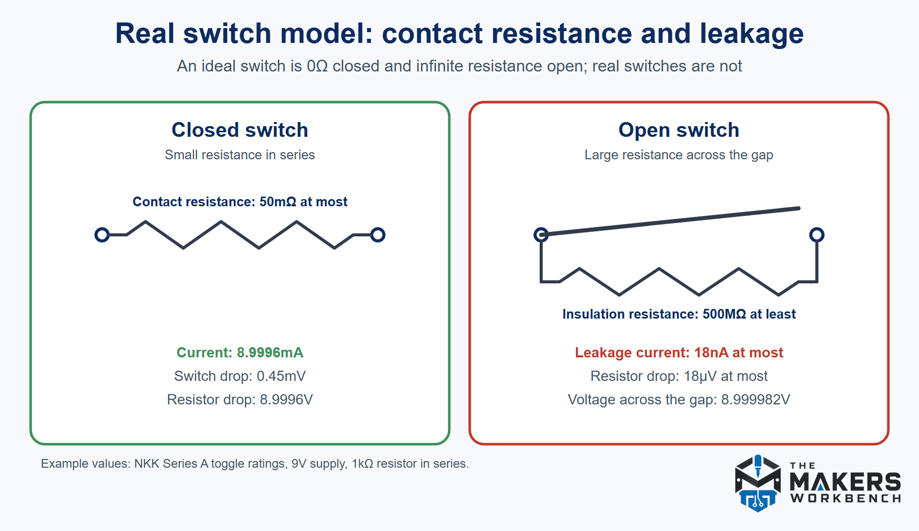
Put the closed switch in the resistor loop from the previous section. Its 50mΩ adds to the 1kΩ in series, for a total of 1,000.05Ω:
I = V ÷ Rtotal = 9V ÷ 1,000.05Ω = 8.9996mA
The current is 8.9996 milliamps, which is 9mA to within 0.0004mA. The switch itself drops 8.9996mA × 50mΩ = 0.45mV, or 0.00045V, and the resistor drops 8.9996V. Together they add back up to 9V.
Now open the switch. The 500MΩ is a minimum rating. If the open gap is no worse than that, the leakage is at most the supply voltage divided by that resistance:
Ileak ≤ 9V ÷ 500MΩ = 18nA
That is 18 nanoamps, or 18 billionths of an amp. The 1kΩ resistor drops at most 18nA × 1kΩ = 18µV (18 microvolts), so the gap still carries 8.999982V. Both effects are far too small to notice, so the ideal model is a good description of a healthy switch.
It stops being a good description when contacts deteriorate. Arc heat and oxidation contaminate the contact surface and raise its resistance [7]. A contact resistance that has crept up to ohms behaves like an extra resistor in the loop, and a contact that makes and loses connection at random opens and closes the loop on its own. The end of a switch's life is some combination of those faults, or a weld that will not release [7]. Contacts wear fastest when a switch opens on a load that resists a change in current, and a coil is the usual example.
Opening a Switch on an Inductive Load
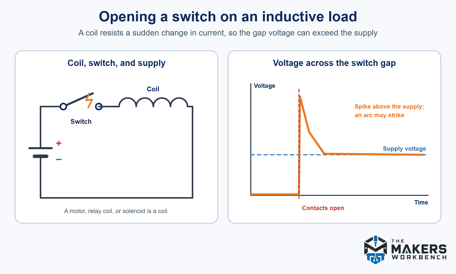
An inductive load is built around a coil of wire, such as a motor, a relay coil, a solenoid, or a transformer. A coil resists any change in the current through it, and the relationship is:
V = L × di/dt
Here V is the voltage across the coil, L is its inductance (measured in henries), and di/dt is how fast the current is changing [7]. A switch that opens forces the current to fall toward zero in a very short time, so di/dt is large, and the voltage across the opening gap can rise far above the supply, often several times higher [7]. The gap between parting contacts is tiny at first and cannot withstand that voltage. The air ionizes and an arc forms, a hot discharge that keeps current flowing across the gap for a moment [7].
An arc needs a minimum voltage and current that depend on the contact metal. For silver the figures are roughly 12V and a few hundred milliamps, and below them no arc can hold [7]. The 9V, 7mA LED circuit in this article is far below both, so its switch never arcs. A motor or relay circuit can sit above them. A micro switch rated for 6A at 250V AC may last about 100,000 mechanical operations but only about 10,000 at full electrical load, because the arc erodes the contacts [7]. On AC the current crosses zero twice per cycle, which gives the arc a chance to go out. On DC there is no zero crossing, so the arc lasts longer and does more damage [7].
Two kinds of protection are common. A diode placed across a DC coil gives the current another path, and a resistor and capacitor network called a snubber placed across the contacts slows the rise of the gap voltage [7]. Later articles on diodes and inductors cover how those work. Opening a circuit is therefore not always harmless. With a resistive load nothing dramatic happens at the break, while with a coil the break itself can do damage.
Intentional Controls and Accidental Breaks
A switch is the one break chosen on purpose: a person or a control circuit sets it open or closed. Fuses and circuit breakers are rated in amps and protect a circuit from excessive current [1]. They do it by opening the loop on purpose when the current exceeds their rating. Other breaks come from faults. A disconnected connector or a loose wire is a break at a joint. A cracked trace on a printed circuit board is a break in the copper path itself. A broken wire is a break in the conductor.
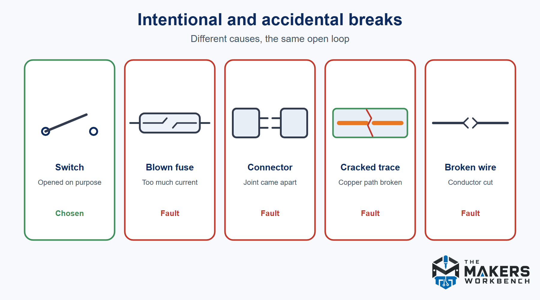
The causes and repairs differ, but the effect on the loop is the same in every case, and it does not depend on where the break is [3]. That is why a dead circuit does not say where it is broken. The voltage across each part does, and a meter can read it.
Finding a Break With a Meter
One rule comes first. Remove power before using a meter's continuity mode. Voltage checks are the opposite: they are made on a powered circuit, and in this article only on a battery-level circuit like the 9V examples. Do not probe line power.
The voltage method follows from the earlier sections. In a powered loop, a break shows up as the full supply voltage across the part that is open and about 0V across the parts that still conduct. In the resistor loop, a reading of 9V across the switch and 0V across the resistor means the switch is open. In a loop with several parts, measure across each part in turn, and the part with the full supply across it is the break.
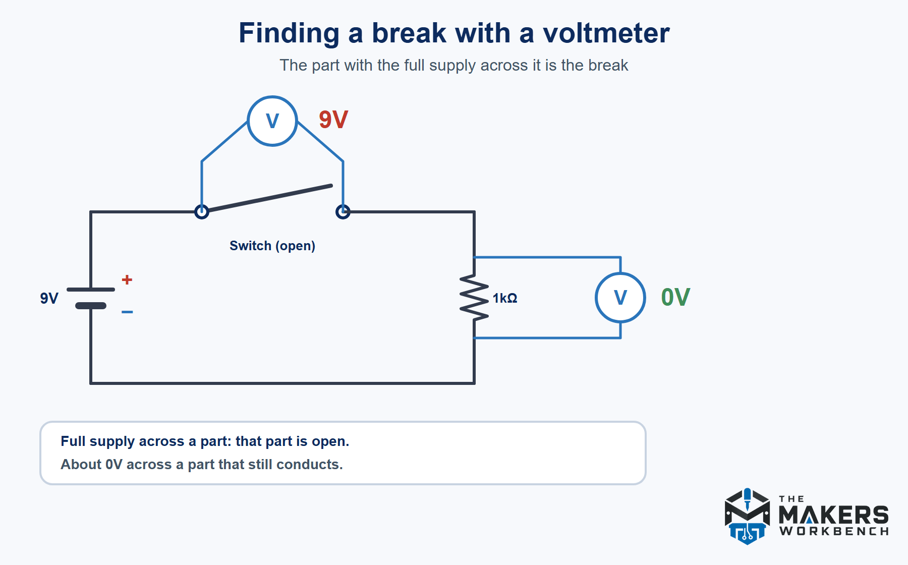
The continuity method measures resistance between two points. A reading below a few ohms means the two points are connected, and the meter sounds a tone. A reading above that means the path is open. The meter measures resistance by supplying its own tiny current, and a live circuit would interfere with that, which is why the circuit under test is turned off first.
A meter is itself a very large resistor, and it affects what it measures. Most digital multimeters have an input resistance greater than 1MΩ [8]. Placed across the open switch in the resistor loop, the meter completes a tiny loop through itself and the 1kΩ resistor. For arithmetic, assume a 10MΩ meter, a round value inside that description:
I = 9V ÷ (10MΩ + 1kΩ) = 0.9µA, and Vmeter = 0.9µA × 10MΩ = 8.9991V
The meter reads 8.9991V, which is 99.99 percent of the 9V supply. The error is negligible here, and it grows as the resistance in the loop approaches the meter's own.
A meter can also show a voltage on a wire that is disconnected but runs close to a live one. The capacitance between the two wires forms a voltage divider with the meter's input, and the meter displays the result. Fluke reports ghost voltages at times as high as 80 to 85 percent of the real voltage, most often at blown fuses and unused wiring in distribution panels [8]. A number on the display shows what the meter measured. It does not prove the wire is live or properly connected. Distribution panels carry line power, and this article does not cover working on them.
A Short History of the Switch and the Circuit
Steady current had to wait for a source that could supply it. Earlier experimenters had Leyden jars, which store charge and release it in a brief spark [9]. Alessandro Volta built his voltaic pile, a stack of alternating metal discs separated by brine-soaked cloth, in 1799. He described it in a letter to Joseph Banks, president of the Royal Society of London, dated March 20, 1800 [9]. When a wire joined the two ends of the stack, a steady current flowed [9]. The wire and the stack formed a closed loop that carried a continuous current, where earlier sources gave only a brief spark.
Opening and closing the loop on purpose became a technology with the telegraph. A few weeks before the Washington to Baltimore demonstration in 1844, Alfred Vail used a simple switch to open and close the circuit [10]. His first device, which he called the Correspondent, was two springy brass contacts pressed together to close the loop [10]. Within about six months he had developed a lever key, and the first message on the first long-distance line, from Washington to Baltimore, went out on May 24, 1844 [10][11]. A telegraph circuit had three parts joined by wire: a battery, a key that completed or broke the circuit, and an electromagnet at the far end that responded to each closure. James Bunnell's steel lever "Triumph" key of 1881 became a widely produced design [10].
The rule that describes voltage around a loop is named for Gustav Kirchhoff (1824 to 1887). His loop rule says the changes in potential around any closed path add up to zero [5]. It is the rule this article used to find the 9V across an open switch.
Common Misconceptions
- "An open circuit has no voltage in it." The loop carries no current, but the full supply voltage appears across the break.
- "A closed circuit is the same as a short circuit." A closed circuit is a complete path that includes a load. A short circuit is a path with almost no resistance, and the next article covers it.
- "An open circuit cannot hurt anything." With a coil in the loop, opening the contacts can strike an arc that erodes them [7].
- "A break only matters if it is close to the load." A break anywhere in the loop stops the current throughout the loop [3].
- "A closed switch is zero ohms and an open switch is infinite ohms." Those are the ideal models. One datasheet gives 50mΩ maximum when closed and 500MΩ minimum when open [6].
- "If the meter shows a voltage, the wire is live and connected." A high-impedance meter can display a ghost voltage on a disconnected wire [8].
Related Articles
- How Voltage Works defines the voltage that appears across a break.
- How Electric Current Works explains the steady current a closed loop carries.
- How Electrical Resistance Works covers resistance, including that of a closed and an open switch.
- How Ohm's Law Works gives the current and voltage calculations used here.
- How Kirchhoff's Circuit Laws Work states the loop rule behind the 9V across an open switch.
- How Electrical Ground Works defines the 0V reference that the voltages are measured from.
References
- OpenStax, “9.1 Electrical Current,” University Physics Volume 2, openstax.org. https://openstax.org/books/university-physics-volume-2/pages/9-1-electrical-current Accessed November 20, 2026.
- OpenStax, “19.2 Series Circuits,” Physics, openstax.org. https://openstax.org/books/physics/pages/19-2-series-circuits Accessed November 20, 2026.
- All About Circuits, “What Are Electric Circuits?,” Electronics Textbook, Volume 1, Chapter 1, allaboutcircuits.com. https://www.allaboutcircuits.com/textbook/direct-current/chpt-1/electric-circuits/ Accessed November 20, 2026.
- Vishay Semiconductors, “TLDR5400 High Intensity LED, 5mm Tinted Diffused Package,” datasheet, document 83003, Rev. 1.8, April 29, 2013, vishay.com. https://wwwlegacy.vishay.com/docs/83003/tldr5400.pdf Accessed November 21, 2026.
- OpenStax, “10.3 Kirchhoff’s Rules,” University Physics Volume 2, openstax.org. https://openstax.org/books/university-physics-volume-2/pages/10-3-kirchhoffs-rules Accessed November 20, 2026.
- NKK Switches, “Series A and Series B Process Sealed Subminiature Toggles,” product sheet, nkkswitches.com. https://www.nkkswitches.com/pdf/A_B_SeriesProductSheet.pdf Accessed November 20, 2026.
- EEPower with Bodo’s Power Systems, “Switching Inductive Loads With a Mechanical Switch”, eepower.com. https://eepower.com/technical-articles/the-arc-across-the-contacts-switching-inductive-loads-with-a-mechanical-switch/ Accessed November 20, 2026.
- Fluke, “Dual Impedance Digital Multimeters,” application note, fluke.com. https://www.fluke.com/en-us/learn/blog/digital-multimeters/dual-impedance-digital-multimeters Accessed November 20, 2026.
- American Physical Society, “March 20, 1800: Volta describes the Electric Battery,” APS News, March 2006, aps.org. https://www.aps.org/apsnews/2006/03/this-month-in-physics-history Accessed November 20, 2026.
- Electronics Notes, “Morse Key History: Telegraph Keys”, radio-electronics.com. https://www.radio-electronics.com/info/radio_history/morse/morsekeydev.php Accessed November 20, 2026.
- Kenyon College Physics, “The Telegraph,” Early Apparatus collection, physics.kenyon.edu. https://physics.kenyon.edu/EarlyApparatus/Electricity/Telegraph/Telegraph.html Accessed November 20, 2026.
Wrapping Up
A circuit carries steady current only around a complete loop, and a break anywhere stops the current everywhere in that loop. An open switch carries the whole supply voltage across its gap with no current through it. Real switches add a little resistance when closed and a little leakage when open, and a coil can strike an arc when its switch opens. A voltmeter across a suspect part finds the break. How Short Circuits Work is next, because it covers the opposite fault, a path with almost no resistance.
Hack The World and Make Awesome.