Stand at the edge of a canyon and shout. A moment later your voice comes bouncing back, and if you counted the seconds in between, you could work out how far away the far wall is. Sound travels at a steady, known speed, so the delay is really a distance in disguise.
The HC-SR04 does exactly this, only it uses a sound too high-pitched for you to hear and it measures the delay in millionths of a second. It's a small, cheap sensor that tells your ESP32 how far away the nearest object is, and it's behind a lot of parking sensors, robot "eyes," and automatic soap dispensers. (An ESP32 is a small, inexpensive computer-on-a-chip with built-in Wi-Fi. The board used here is the ESP32-DevKitC.)
In this tutorial we'll look at how the sensor measures distance, what its four pins do, and what the signals on those pins look like. I'll also point out the one wiring trap that catches almost everyone who pairs this sensor with an ESP32. Then you'll build a working distance meter, either on a real breadboard or in The Makers Workbench Electronics Lab.
What You'll Learn
- How an ultrasonic sensor turns a sound echo into a distance
- What the TRIG and ECHO pins do, and what their pulses look like over time
- How to turn an echo time into centimeters
- Why the HC-SR04's ECHO pin can hurt an ESP32, and how a voltage divider fixes it
- How to time a pulse yourself, and why
pulseIn()is the safer shortcut - What makes readings go wrong, and how to spot it
How Does an Ultrasonic Sensor Measure Distance?
Ultrasonic means "above the range of human hearing." People hear sounds up to roughly 20 kHz (a kilohertz, kHz, is a thousand vibrations per second). The HC-SR04 makes a sound at 40 kHz, twice as high as the top of your hearing, so it works silently. Bats and dolphins use the same trick to find things in the dark.
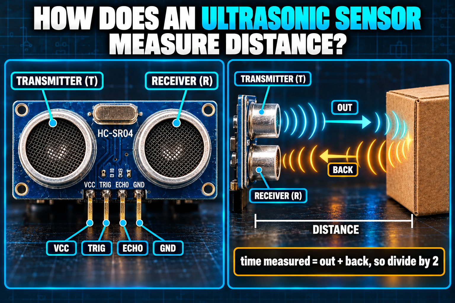
The module has two round metal cylinders on the front. One is the transmitter, a tiny speaker. The other is the receiver, a tiny microphone. The transmitter sends out a short burst of sound, the sound hits an object and bounces back, and the receiver hears the echo. The sensor times the trip.
Now the arithmetic. Sound moves through room-temperature air at about 343 meters per second. That's hard to picture, so here it is in the units we need: sound covers about 0.0343 centimeters in one microsecond (µs, one millionth of a second). Put another way, in 100 µs the sound travels about 3.4 cm.
The echo makes a round trip, out to the object and back, so the time you measure covers twice the distance you want. The formula is:
distance (cm) = echo time (µs) × 0.0343 ÷ 2
Say the echo takes 1,166 µs. Then 1,166 × 0.0343 = 40.0 cm for the whole trip, so the object is 20.0 cm away.
One footnote about that 343. Sound travels a little faster in warm air, about 0.6 meters per second faster for each degree Celsius. On a cold day the sensor reads slightly long, and on a hot day slightly short. For a hobby project the error is small, but it's good to know it exists.
What Do the Four Pins Do?
| Pin | What it does |
|---|---|
| VCC | Power in. The classic HC-SR04 wants 5 V. |
| TRIG | Trigger input. You send a short pulse here to say "measure now." |
| ECHO | Echo output. The sensor holds this pin HIGH for as long as the echo took to return. |
| GND | Ground, the shared return path for the electricity. |
Notice what the sensor doesn't do: it never sends you a number. It sends you a pulse whose width is the number. Your code has to measure that width.
What Do the TRIG and ECHO Signals Look Like?
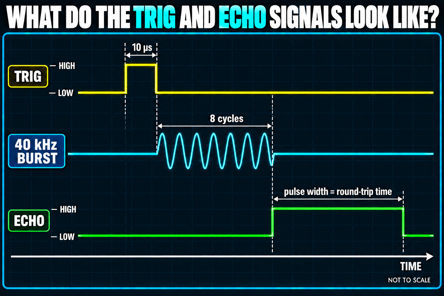
A pulse is a pin going HIGH for a short while and then LOW again. The conversation goes like this:
- Your ESP32 sets TRIG HIGH for 10 µs, then LOW. That's a tap on the shoulder.
- The sensor sends out eight bursts of 40 kHz sound.
- The sensor sets ECHO HIGH the moment the bursts leave.
- When the echo comes back, the sensor sets ECHO LOW again.
The time ECHO spent HIGH is your round-trip time. If no echo ever returns (nothing in range), the sensor gives up after about 38 milliseconds and drops ECHO anyway.
Can the ESP32 Read the ECHO Pin Safely?
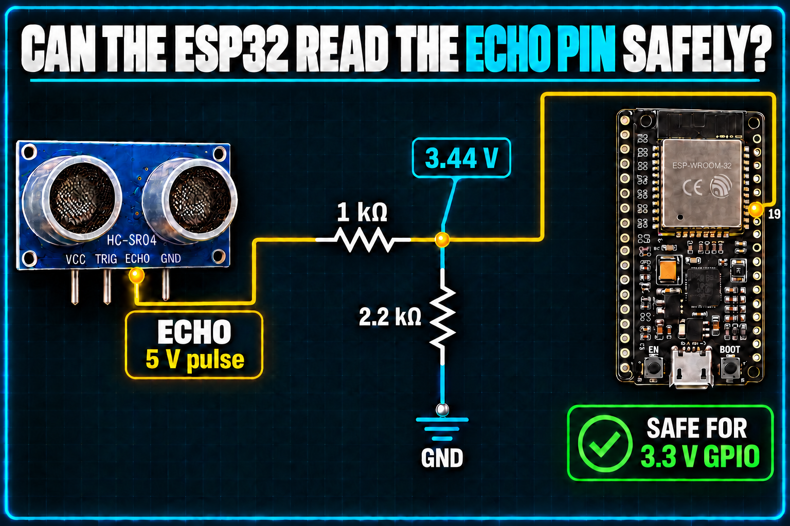
This is the gotcha I promised. The HC-SR04 is a 5 V part, so when its ECHO pin goes HIGH, it sits at about 5 V. The ESP32's pins run on 3.3 V and are not 5 V tolerant. Feeding 5 V into a pin that expects 3.3 V may work for a while, but it overstresses the chip, and it can kill the pin or the board.
The fix is a voltage divider, which is just two resistors in a row that share the voltage between them. Picture a ruler. If you grab it at a point partway along, the distance from the end to your hand is a fraction of the total length. A divider "grabs" a fraction of the voltage in the same way. The formula is:
Vout = Vin × R2 ÷ (R1 + R2)
With R1 = 1 kΩ and R2 = 2.2 kΩ (a kilohm, kΩ, is 1,000 ohms, the unit of electrical resistance), 5 V × 2.2 ÷ 3.2 = 3.44 V. The ESP32 reads that as a clean HIGH without being overstressed.
DO NOT CONNECT THE ECHO PIN DIRECTLY TO THE ESP32. Always route it through the divider. Some sensor variants (often sold as "HC-SR04P" or "3.3 V version") run entirely on 3.3 V and need no divider, so check your listing. If you're not sure, use the divider anyway, because it costs nothing.
The TRIG pin is fine. It's an input, and a 3.3 V signal from the ESP32 is plenty to trigger it.
Bill of Materials
You'll need the parts below. The ESP32-DevKitC is Espressif's own board, and its official documentation covers it in full. The resistor kit gives you the 1 kΩ and 2.2 kΩ resistors for the divider.
| Component | Description | Buy on Amazon | Buy on Temu | Buy on SparkFun | Buy on Seeed Studio | Datasheet |
|---|---|---|---|---|---|---|
| ESP32-DevKitC development board | Espressif's official ESP32 board (ESP32-WROOM module, Micro-USB, Wi-Fi and Bluetooth) | Amazon Link | Temu Link | Temu Link | Temu Link | ESP32 datasheet |
| HC-SR04 ultrasonic sensor | The 5 V version with four pins: VCC, TRIG, ECHO, GND | Amazon Link | Temu Link | Temu Link | Temu Link | HC-SR04 datasheet |
| Resistor kit | You need one 1 kΩ and one 2.2 kΩ resistor for the ECHO voltage divider | Amazon Link | Temu Link | SparkFun Link | Seeed Link | N/A |
| Breadboard & jumper wires | For prototyping connections without soldering | Amazon Link | Temu Link | SparkFun Link | Seeed Link | N/A |
| USB data cable | Powers the ESP32 and uploads code. Make sure it carries data, not just power. | Amazon Link | Temu Link | SparkFun Link | Temu Link | N/A |
The products linked above may contain affiliate links. The Makers Workbench earns from qualifying purchases when these links are used.
How Do I Build the Distance Meter?
For the practical project, the ESP32 will fire the sensor twice a second and print the distance in the Serial Monitor. (The Serial Monitor is a window in the Arduino IDE, under Tools > Serial Monitor, where your board and computer swap text.)
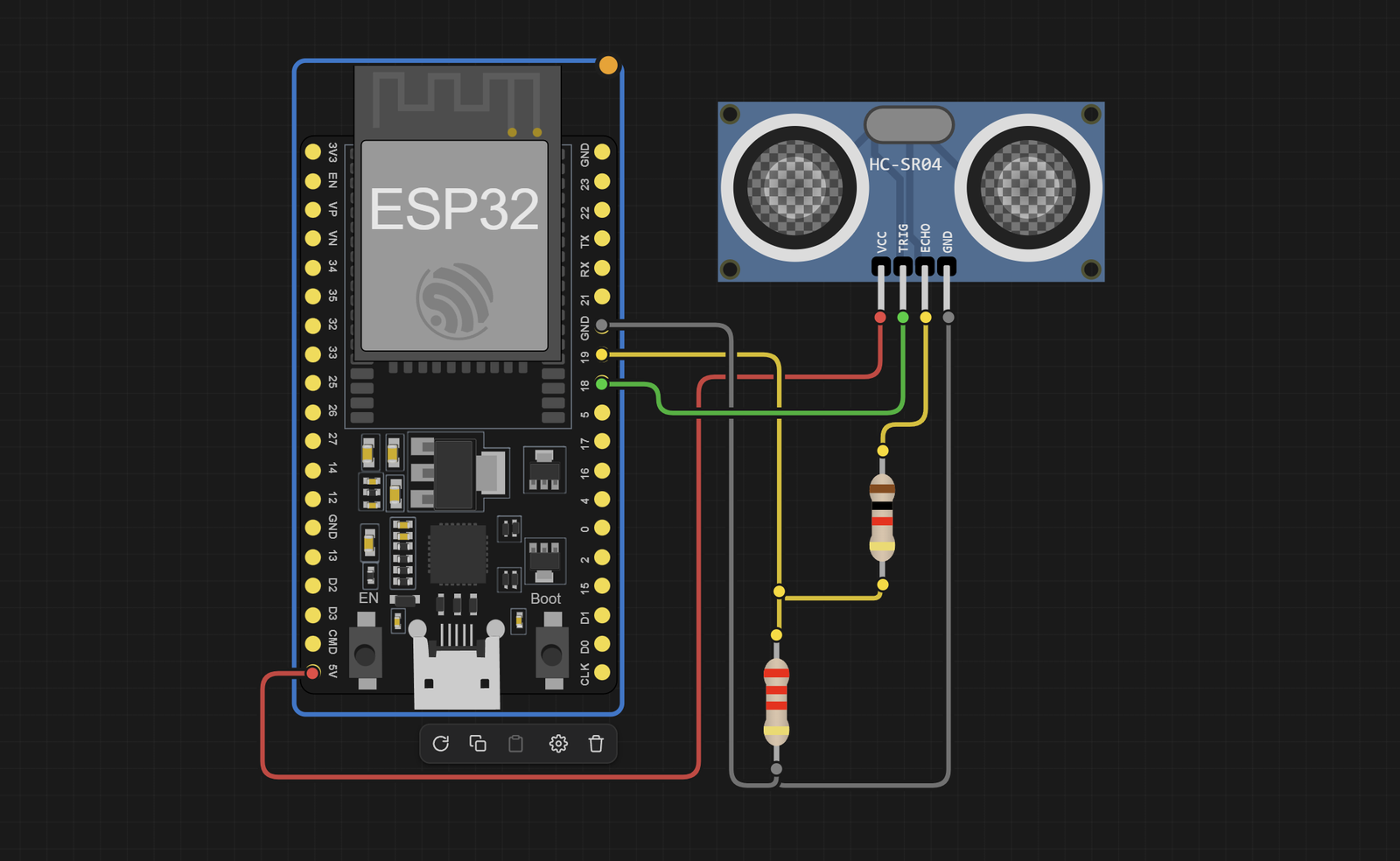
Here is the point-to-point wiring. "Junction" means the spot where three things meet, which on a breadboard is one numbered row.
| From | To | Why |
|---|---|---|
| HC-SR04 VCC | ESP32 VIN (the 5 V pin) | The sensor wants 5 V |
| HC-SR04 GND | ESP32 GND | Shared ground |
| HC-SR04 TRIG | ESP32 GPIO 18 | Our trigger output |
| HC-SR04 ECHO | 1 kΩ resistor, first leg | Start of the divider |
| 1 kΩ resistor, second leg | ESP32 GPIO 19 (junction) | Our echo input, now at about 3.4 V |
| Same junction | 2.2 kΩ resistor, first leg | Bottom half of the divider |
| 2.2 kΩ resistor, second leg | ESP32 GND | Completes the divider |
How Do I Measure the Echo Pulse by Hand?
Before the shortcut, let me show you what it saves you from. You could time the ECHO pulse yourself by watching the pin and reading the clock. The ESP32's micros() function returns the number of microseconds since power-on:
// The hard way: time the ECHO pulse manually
while (digitalRead(ECHO_PIN) == LOW) {}      // wait here until ECHO goes HIGH
unsigned long riseTime = micros();           // note the time the pulse started
while (digitalRead(ECHO_PIN) == HIGH) {}     // wait here until ECHO falls back to LOW
unsigned long width = micros() - riseTime;   // pulse width in microseconds
This works, but look at those while loops. If the sensor is unplugged or ECHO never changes, the loops wait forever and your ESP32 freezes. You would have to add your own timeout to each one.
Arduino already has a function for this exact job. pulseIn(pin, level, timeout) waits for the pin to reach the given level, times how long it stays there, and gives up after the timeout (in microseconds). It returns 0 if time runs out. The project below uses it.
What Does the Full Sketch Look Like?
// HC-SR04 distance meter for the ESP32
// TRIG goes to GPIO 18. ECHO goes to GPIO 19 through a 1k and 2.2k voltage divider.

#define TRIG_PIN 18                  // GPIO 18 sends the trigger pulse to the sensor
#define ECHO_PIN 19                  // GPIO 19 listens for the echo pulse (3.3 V after the divider)

const float CM_PER_US = 0.0343;      // centimeters sound travels in one microsecond (at about 20 C)

float measureCm() {
  digitalWrite(TRIG_PIN, LOW);       // start from a clean LOW
  delayMicroseconds(2);              // let the pin settle for 2 microseconds
  digitalWrite(TRIG_PIN, HIGH);      // begin the 10 microsecond trigger pulse
  delayMicroseconds(10);             // hold HIGH for 10 microseconds
  digitalWrite(TRIG_PIN, LOW);       // end the pulse: the sensor now fires its sound burst

  long width = pulseIn(ECHO_PIN, HIGH, 30000UL);  // time ECHO stays HIGH, give up after 30,000 us
  if (width == 0) {                  // 0 means pulseIn timed out
    return -1.0;                     // no echo came back, so report "no reading"
  }
  return width * CM_PER_US / 2.0;    // round trip, so halve the distance
}

void setup() {
  Serial.begin(115200);              // start the Serial Monitor connection at 115200 baud
  pinMode(TRIG_PIN, OUTPUT);         // TRIG is an output: we talk to the sensor
  pinMode(ECHO_PIN, INPUT);          // ECHO is an input: the sensor talks to us
  Serial.println("HC-SR04 ready");   // a friendly sign of life
}

void loop() {
  float cm = measureCm();            // take one measurement
  if (cm < 0) {                      // did we get the "no reading" value?
    Serial.println("Out of range");  // nothing was close enough to bounce an echo back
  } else {
    Serial.printf("Distance: %.1f cm\n", cm);  // print the distance to one decimal place
  }
  delay(500);                        // wait half a second before the next measurement
}
(Baud is the speed of the text connection. Your Serial Monitor must be set to 115200 to match, or you'll see garbage.)
The wiring table and the code agree on the same two pin numbers, 18 and 19. If you move the wires to different GPIOs later, change the two #define lines and nothing else.
Try the Distance Meter in the Lab
No parts yet? Run it in The Makers Workbench Electronics Lab. In the Lab, build the same circuit from the wiring table above, using an ESP32, an HC-SR04, a 1 kΩ resistor, and a 2.2 kΩ resistor.
The Lab circuit is wired like this:
| From | To | Why |
|---|---|---|
| HC-SR04 VCC | ESP32 5V | The sensor wants 5 V |
| HC-SR04 GND | ESP32 GND | Shared ground |
| HC-SR04 TRIG | ESP32 GPIO 18 | Our trigger output |
| HC-SR04 ECHO | 1 kΩ resistor, first leg | Start of the divider |
| 1 kΩ resistor, second leg | ESP32 GPIO 19 (junction) | Our echo input, now at about 3.4 V |
| Same junction | 2.2 kΩ resistor, first leg | Bottom half of the divider |
| 2.2 kΩ resistor, second leg | ESP32 GND | Completes the divider |
Load the sketch, press Run, and open the Serial Monitor panel. You should see a line like Distance: 40.0 cm every half second. Click the HC-SR04 in the Lab to open its controls, then move the Distance slider (it runs from 2 to 400 cm). The readings follow your change, which is a fast way to test the formula from earlier. Set it to 20 and you should read about 20 cm.
Why Are My Readings Wrong?
- Jumpy numbers. Sound bounces. Soft or angled surfaces, such as a couch or a coat, absorb or deflect the burst, so the echo comes back weak or not at all. Aim at a flat, hard surface to test.
- Nothing closer than about 2 cm. The receiver can't hear an echo that returns while the transmitter is still "talking." The sensor works from about 2 cm out to roughly 400 cm.
- A wide field of view. The sound spreads out in a cone about 15 degrees wide, so a nearby object off to the side can steal the reading.
- Constant "Out of range." Check TRIG and ECHO aren't swapped, the divider's junction really lands on GPIO 19, and the sensor has 5 V on VCC.
Two more ideas to try. A single reading can be an outlier, so you can take five and keep the middle one (the median) for a steadier number. And if you add a temperature sensor, you can correct the speed of sound for the actual air temperature.
Conclusion
The HC-SR04 reports distance as a time. You trigger it with a 10 µs pulse, measure how long ECHO stays HIGH, multiply by 0.0343, and divide by two. You also know why the ECHO pin needs a voltage divider on a 3.3 V board, and why pulseIn() beats a hand-rolled timing loop.
Next up in the series: the servo motor, which takes a pulse width as an input instead of giving one as an output.