Picture a classroom where the teacher wants to ask one student a question. She doesn't run a separate cable to every desk. She just says a name out loud, that student answers, and everyone else stays quiet. One room, one conversation at a time, as many students as will fit.
I²C (say "I squared C," short for Inter-Integrated Circuit) works the same way. It's a way for a microcontroller to talk to many chips using only two shared wires. Sensors, displays, clocks, and memory chips all speak it, and once you understand it, a huge pile of parts opens up to your ESP32. (An ESP32 is a small, inexpensive computer-on-a-chip with built-in Wi-Fi. We're using the ESP32-DevKitC board.)
In this tutorial we'll cover what those two wires do, how the ESP32 picks one device out of many, and why two small resistors matter more than they look. Then we'll put it to work with the BMP280, a sensor that measures air pressure and temperature, and build a project that prints readings from it. You can build it on a breadboard or in The Makers Workbench Electronics Lab.
What You'll Learn
- What the SDA and SCL wires carry, and what a clock signal is
- How device addresses let one pair of wires serve many chips
- What a start condition, an ACK, and a stop condition are
- What pull-up resistors do, and why the bus needs them
- How to scan the bus and find a device's address
- How to read a chip's ID the hard way, and why a library is worth installing
- How to read pressure, temperature, and an altitude estimate from a BMP280
How Do the Two Wires Work?
The two wires have names:
- SDA (serial data) carries the information itself, one bit at a time. A bit is a single 1 or 0, which on a wire means HIGH or LOW voltage.
- SCL (serial clock) carries a steady ticking signal that says "read the data line now."
Think of a metronome. If I tap out a message in a pattern, you need to know when each beat lands, or you can't tell where one bit ends and the next begins. The clock is that metronome. Standard I²C ticks at 100 kHz (100,000 ticks a second), and "fast mode" ticks at 400 kHz. A kilohertz, kHz, is a thousand ticks per second.
The device in charge, your ESP32, makes the clock and starts every conversation. We call it the controller, and the chips it talks to are peripherals. (Older tutorials say "master" and "slave." It's the same idea with older words.)
How Does the ESP32 Pick One Device Out of Many?
Every I²C chip has an address, a 7-bit number that works like the student's name in the classroom. The BMP280's address is usually written 0x76. The 0x in front means the number is in hexadecimal, a way of counting in sixteens that programmers use because it fits neatly into binary. So 0x76 is just the number 118.
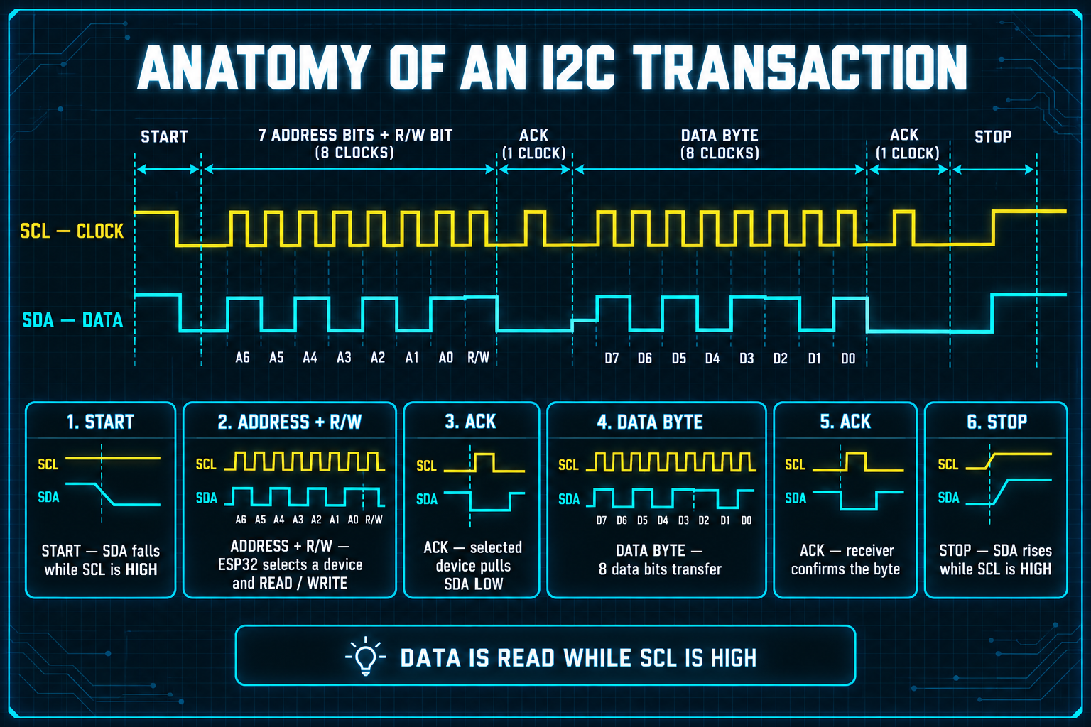
A conversation, called a transaction, goes like this:
- Start condition. The controller pulls SDA LOW while SCL is still HIGH. That never happens during normal data, so every chip knows "someone is about to speak."
- Address and direction. The controller sends the 7-bit address plus one extra bit: read from the device, or write to it.
- ACK. The addressed chip pulls SDA LOW for one tick, which means "acknowledged, I'm here." If nobody answers, the line stays HIGH (a NACK) and the controller knows the address is empty.
- Data bytes. Bytes pass in whichever direction was chosen, each followed by an ACK.
- Stop condition. The controller lets SDA rise while SCL is HIGH, and the bus is free again.
Why Does I²C Need Pull-Up Resistors?
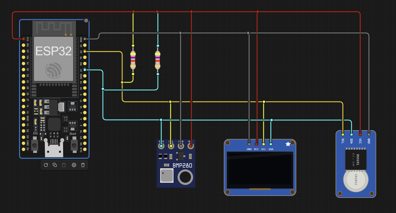
Here is the strangest part of I²C. No chip on the bus ever drives a wire HIGH. They can only pull it LOW, like pulling a rope down. Something else has to lift it back up, and that something is a pull-up resistor: a resistor from each wire to 3.3 V that gently pulls the line HIGH whenever nobody is pulling it down.
This is what lets many chips share one wire safely. If two chips could push opposite voltages at the same moment, they would fight and could damage each other. With pull-ups, the worst case is that two chips pull LOW together, which is harmless.
The good news is that most sensor modules, the BMP280 included, already have pull-ups printed on the little board (typically 4.7 kΩ or 10 kΩ; a kilohm, kΩ, is 1,000 ohms, the unit of electrical resistance). You rarely add your own, but now you know why a bare chip with no pull-ups shows up as "device not found."
What Is a BMP280?
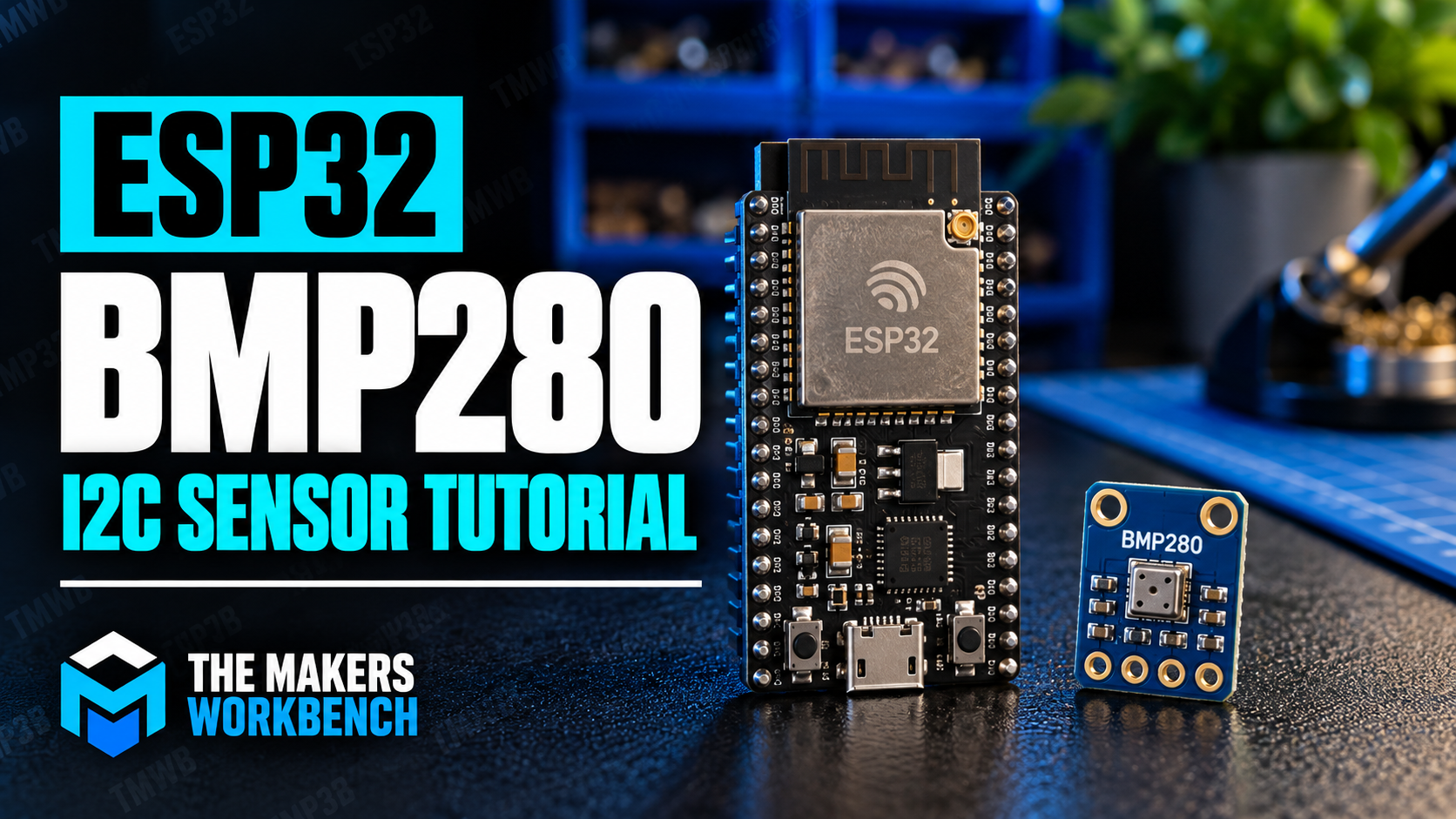
The BMP280, made by Bosch, is a tiny sensor with two jobs.
It measures air pressure, the weight of the air column above you, reported in hectopascals (hPa). At sea level on an average day it's around 1013 hPa, and it falls as you climb. A rise of about 100 meters drops it by roughly 12 hPa, so the sensor can also estimate altitude.
It also measures temperature, in degrees Celsius.
Three things to know before you buy one:
- It's a 3.3 V chip. Power it from the ESP32's 3V3 pin.
- Beware the lookalike. The BME280 is a close cousin that adds humidity, and sellers sometimes mix up the two names. Their chip IDs differ (the BMP280 reports
0x58, the BME2800x60), and we'll use that fact in a moment to check which one you actually have. - The address can be
0x76or0x77. A pin called SDO on real modules chooses between them. If the sketch can't find your sensor, try the other address first.
A real module often has six pins (VCC, GND, SCL, SDA, CSB, SDO). We only need the first four. Leave the other two alone.
Which ESP32 Pins Carry I²C?
The ESP32 can put I²C on almost any pins, but the default pair is GPIO 21 for SDA and GPIO 22 for SCL. We'll use those, and the sketch states them explicitly with Wire.begin(21, 22). (Wire is the Arduino library that handles I²C, and it comes built in.)
Bill of Materials
| Component | Description | Buy on Amazon | Buy on Temu | Buy on SparkFun | Buy on Seeed Studio | Datasheet |
|---|---|---|---|---|---|---|
| ESP32-DevKitC development board | Espressif's official ESP32 board (ESP32-WROOM module, Micro-USB, Wi-Fi and Bluetooth) | Amazon Link | Temu Link | Temu Link | Temu Link | ESP32 datasheet |
| BMP280 pressure and temperature sensor module | 3.3 V I²C breakout board. Check the listing says BMP280, not BME280. | Amazon Link | Amazon Link | Amazon Link | Amazon Link | BMP280 datasheet |
| Breadboard & jumper wires | For prototyping connections without soldering | Amazon Link | Temu Link | SparkFun Link | Seeed Link | N/A |
| USB data cable | Powers the ESP32 and uploads code. Make sure it carries data, not just power. | Amazon Link | Temu Link | SparkFun Link | Temu Link | N/A |
The products linked above may contain affiliate links. The Makers Workbench earns from qualifying purchases when these links are used.
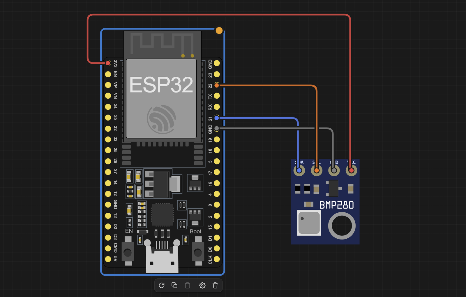
How Do I Wire the BMP280?
| From | To | Why |
|---|---|---|
| BMP280 VCC | ESP32 3V3 | The chip runs on 3.3 V |
| BMP280 GND | ESP32 GND | Shared ground |
| BMP280 SDA | ESP32 GPIO 21 | The data wire |
| BMP280 SCL | ESP32 GPIO 22 | The clock wire |
CAUTION: don't connect VCC to the 5 V pin unless your module's listing says it has an onboard regulator that allows it. A bare BMP280 chip can be damaged by 5 V.
How Do I Find a Device's Address?
Before trusting any I²C part, ask the bus who's there. This sketch tries every possible address and reports which ones answered with an ACK:
// I²C scanner: reports every address that answers on the bus
#include <Wire.h>                          // the built-in I2C library

void setup() {
  Serial.begin(115200);                    // start the Serial Monitor connection
  Wire.begin(21, 22);                      // SDA on GPIO 21, SCL on GPIO 22
  Serial.println("Scanning...");
  for (byte address = 1; address < 127; address++) {   // try every 7-bit address
    Wire.beginTransmission(address);       // start a transaction aimed at this address
    if (Wire.endTransmission() == 0) {     // 0 means a device sent an ACK
      Serial.printf("Found a device at 0x%02X\n", address);  // print the address in hex
    }
  }
  Serial.println("Done");
}

void loop() {}                             // nothing to repeat: the scan runs once
With the BMP280 wired up, you should see Found a device at 0x76 (or 0x77). If you see nothing, the wiring is the problem, not the code.
How Do I Read the Chip Without a Library?
To feel what a library saves you, let's do one read by hand. Every I²C chip has numbered registers, which are like labeled mailboxes holding its settings and measurements. The BMP280 keeps its ID number in register 0xD0:
Wire.beginTransmission(0x76);       // address the sensor
Wire.write(0xD0);                   // say "I want to look at register 0xD0"
Wire.endTransmission(false);        // finish asking, but keep the bus for the reply
Wire.requestFrom(0x76, 1);          // ask the sensor for 1 byte
byte id = Wire.read();              // read the answer: 0x58 means BMP280, 0x60 means BME280
That's five lines to read one number. Real temperature and pressure are harder, because the raw readings are meaningless until you run them through about a dozen calibration values stored in the chip and a page of math from the datasheet. The library does all of that for you.
Installing the Libraries
In the Arduino IDE, open Sketch > Include Library > Manage Libraries, search for Adafruit BMP280, and install Adafruit BMP280 Library. The IDE will ask whether to also install its dependencies, Adafruit BusIO and Adafruit Unified Sensor. Click Install all. If you skip the dependencies, the compile fails with a "file not found" error.
What Does the Full Sketch Look Like?
// BMP280 pressure and temperature over I²C on the ESP32
// SDA to GPIO 21, SCL to GPIO 22, VCC to 3V3, GND to GND

#include <Wire.h>                          // the built-in I2C library
#include <Adafruit_BMP280.h>               // the library that knows the BMP280's registers and math

Adafruit_BMP280 bmp;                       // one object represents our sensor

void setup() {
  Serial.begin(115200);                    // start the Serial Monitor connection
  Wire.begin(21, 22);                      // start I2C with SDA on 21 and SCL on 22
  if (!bmp.begin(0x76)) {                  // look for the sensor at address 0x76 (the library assumes 0x77 otherwise)
    Serial.println("BMP280 not found! Check wiring and address.");
    while (true) delay(10);                // stop here, there is nothing to measure
  }
  Serial.println("BMP280 ready");
}

void loop() {
  float tempC = bmp.readTemperature();     // temperature in degrees Celsius
  float hPa = bmp.readPressure() / 100.0;  // pressure arrives in pascals, so divide by 100 for hPa
  float altitude = bmp.readAltitude(1013.25);  // estimate height using standard sea-level pressure

  Serial.printf("Temp: %.2f C  Pressure: %.2f hPa  Altitude: %.1f m\n", tempC, hPa, altitude);
  delay(2000);                             // wait 2 seconds between readings
}
The wiring table and the sketch agree on GPIO 21 and 22. That altitude number is only an estimate, because it assumes today's sea-level pressure is exactly 1013.25 hPa, and real weather changes it constantly. Expect it to wander by tens of meters from one day to the next.
Try the BMP280 Project in the Lab
Build the four-wire circuit from the table in The Makers Workbench Electronics Lab, using an ESP32 and a BMP280.
The Lab circuit is wired like this:
| From | To | Why |
|---|---|---|
| BMP280 VCC | ESP32 3V3 | The chip runs on 3.3 V |
| BMP280 GND | ESP32 GND | Shared ground |
| BMP280 SDA | ESP32 GPIO 21 | The data wire |
| BMP280 SCL | ESP32 GPIO 22 | The clock wire |
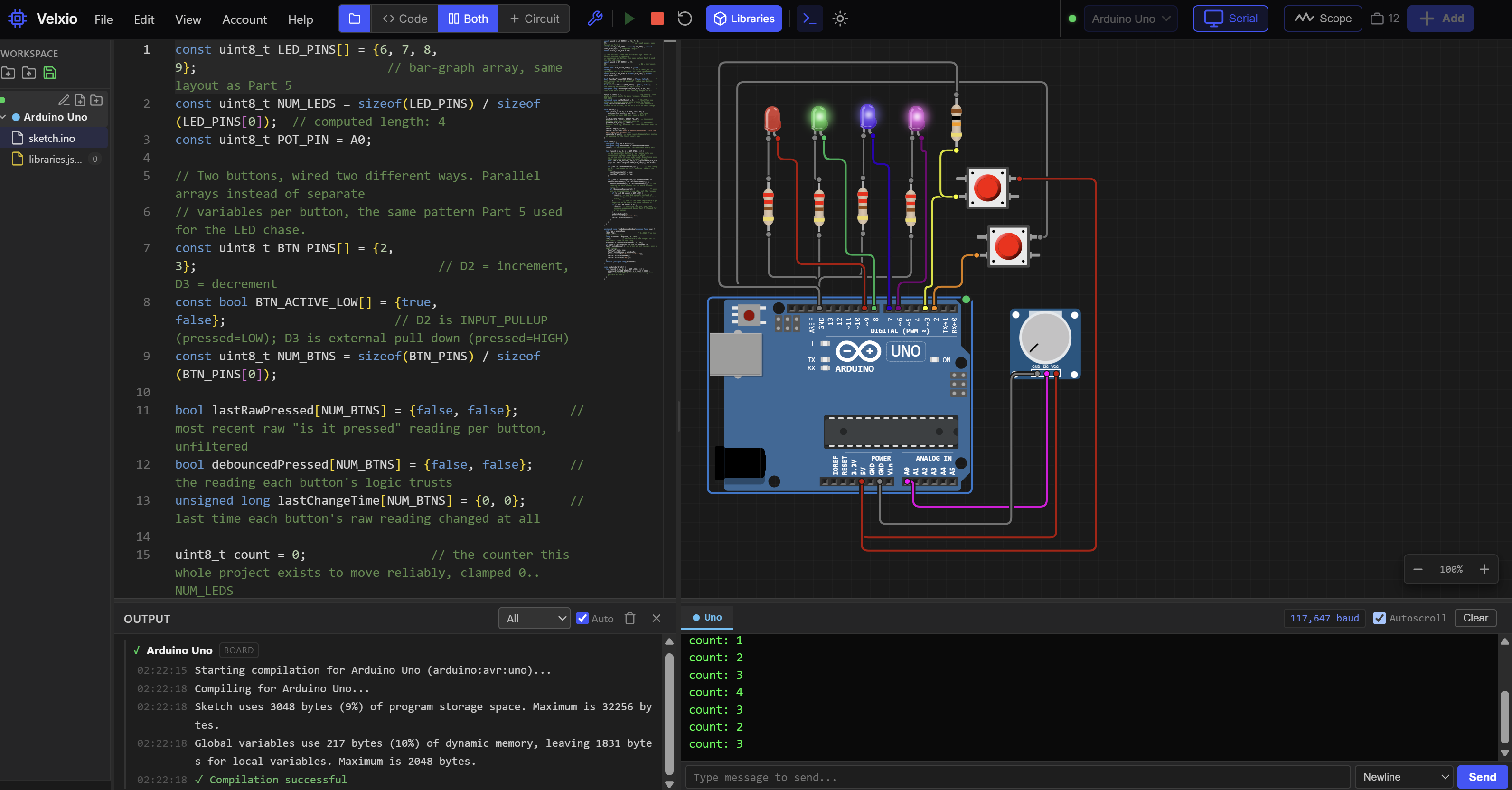
The project opens with the full sketch loaded. To try the scanner first, paste the scanner sketch from earlier into the editor in its place and press Run. It should report the BMP280 at 0x76. The simulator may also list a second address, 0x30, that doesn't belong to any part in the circuit. This is a quirk of the simulator, so ignore it. Then load the full sketch again and open the Serial Monitor. You should see a line like Temp: 25.00 C Pressure: 1013.25 hPa Altitude: 0.0 m every two seconds. Click the BMP280 in the Lab to open its controls, then move the Temperature or Pressure slider. The readings follow within a couple of seconds, and lowering the pressure raises the altitude estimate.
What If It Says "BMP280 Not Found"?
- Try the other address. Change
0x76to0x77. - Check SDA and SCL aren't swapped. It's the classic mistake, and nothing visibly goes wrong when you make it. The sensor simply never answers.
- Run the scanner. If it finds nothing, the code can't help you.
- Check the chip ID. If the scanner finds a device but
begin()still fails, you may have a BME280. Read register0xD0and look for0x60.
Conclusion
I²C is two wires, a clock to keep time, and an address to pick the right chip. You've seen what a start condition, an ACK, and a stop condition do, why pull-up resistors make sharing possible, and how to scan a bus and read a register by hand. You've also read real pressure and temperature from a BMP280.
Next in the series: Wi-Fi, where the ESP32 stops being a lonely board on your desk and starts talking to the network.