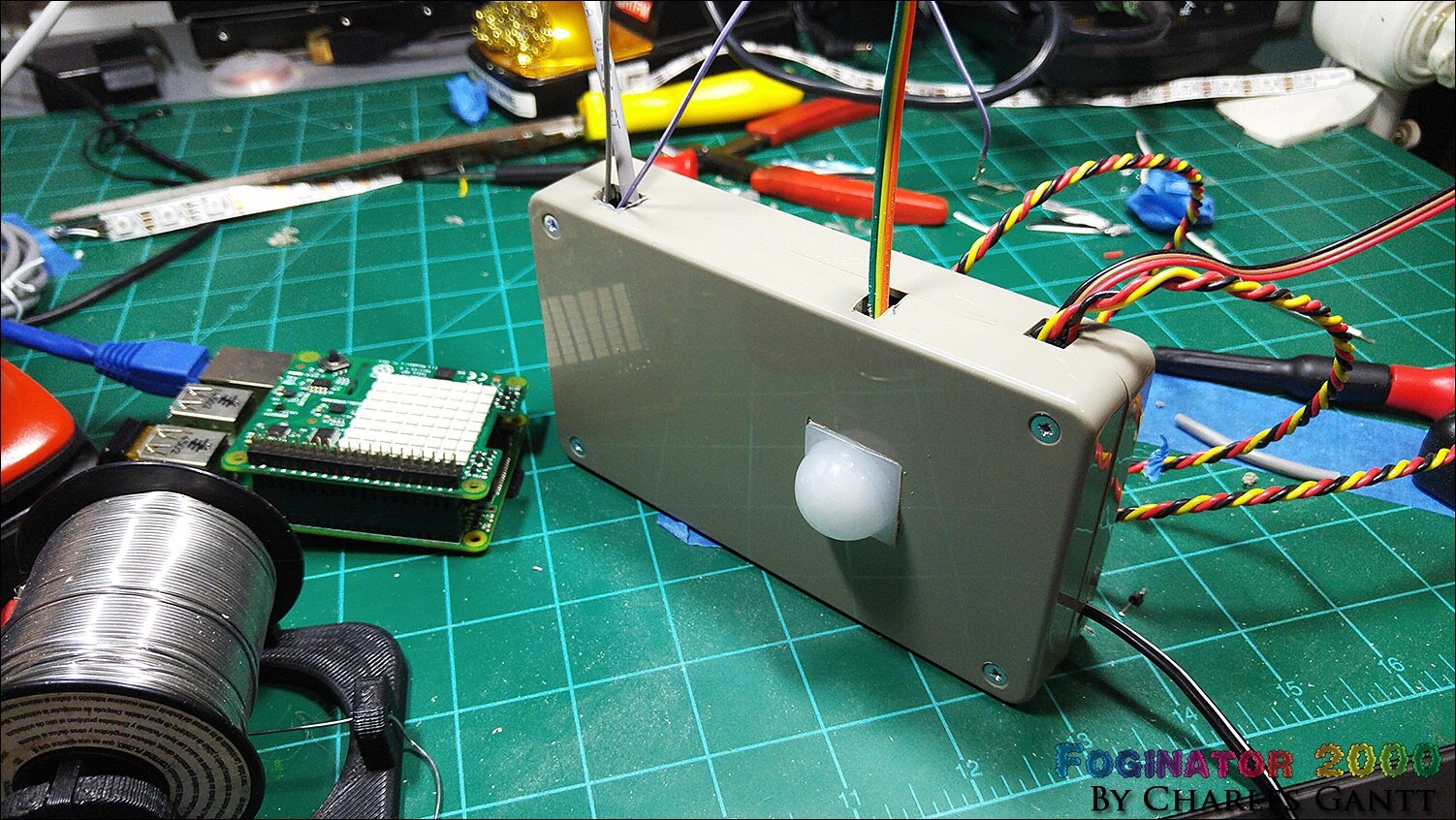
Originally published on the element14 Community by Charles Gantt. This archived edition preserves the original project text, images, and video links.
Part 1: Foginator 2000: #001 Project Introduction

Halloween has always been one of my favorite holidays, so much so that I founded a business that makes professional-grade props and controllers for Haunted Houses. This naturally led to Element14 asking me to create a couple of projects that were easy enough for the community to follow along and replicate the project at home. For my second project, I am going to be creating a automated Fog Machine controller that utilizes a Raspberry Pi, and the new Sense Hat.
The Concept

The basis of this project is to utilize the all new Sense Hat from the Raspberry Pi Foundation to work in conjunction with the Raspberry Pi and a Relay to activate a fog machine when guest trigger a motion sensor. For those of you who might not follow new Raspberry Pi products as myself, the Sense Hat features an array of environment sensors that relay data back to the Raspberry Pi. To be honest, I struggled to figure out how I would tie the Sense Hat back into this project, and after a few conversations with friends I think I have come up with an idea.
I am going to utilize the Sense HatSense Hat to log data about the environmental conditions on Halloween Night and use the fog machine triggers to log what I will call a “Trick or Treat” event. When the night is over, I will compile the data and try to determine if swings in temperature, humidity, or air pressure correlates to a rise or fall in trick or treat events.
I will also utilize a few more of the Raspberry Pi’s GPIO pins to trigger some special effects lighting (NeoPixels), and will play an array of spooky ambient sounds, halloween-themed music, and (if time allows) audio events when the fog machine is triggered. One final bonus feature will be to integrate some form of remote notification when a trick or treat event occurs.
This project will progress a little faster than my Trick or Trivia Candy Dispenser project, mostly because I am building both at the same time. I purposely kept this project a little more simple for this reason. You will also note that I have chosen to use an off-the-shelf relay module this time instead of building my own as I will be doing in my other project. This is both in the spirit of saving some time, but as well to illustrate that there is alternative solutions that are ok to use as well.
The Hardware
Newark Part No. | Notes | Qty | Manufacturer / Description |
38Y646738Y6467 | RPi | 1 | RASPBERRY PI 2, MODEL B |
38Y647038Y6470 | SD Card | 1 | RASPBERRY PI 8GB NOOBS MICRO SD CARD |
44W493244W4932 | PSU | 1 | USB PORT POWER SUPPLY 5V, 1A |
06W104906W1049 | USB Cable | 1 | USB A PLUG TO MICRO USB B PLUG |
53W628553W6285 | WiFi Dongle | 1 | USB WIFI MODULE |
18J555818J5558 | Home Pir Sensor | 1 | PIR MOTION SENSOR |
40P118440P1184 | Speaker | 1 | SPEAKER, 20 kHz, 8OHM, 4W |
26Y845826Y8458 | Fog Coloring Rings | 1 | NEOPIXEL RING - 16 X WS2812 |
26Y851226Y8512 | Ambient LEDs | 1 | NEOPIXEL 8MM THROUGH HOLE LED |
26Y852826Y8528 | AMbient LEDs | 1 | NEOPIXEL 5MM THROUGH HOLE LED |
26Y846026Y8460 | Mood LEDs | 1 | NEOPIXEL DIGITAL RGB 1M 144LED BLACK |
34C109234C1092 | PSU Vreg | 1 | LM7805 LINEAR VOLTAGE REGULATOR, 5V, TO-220-3 |
58K379658K3796 | PSU LED Resistor | 1 | METAL FILM RESISTOR, 1KOHM, 250mW, 1% |
17F216517F2165 | PSU Filter Cap | 1 | CERAMIC CAPACITOR 0.1UF, 50V, X7R, 20% |
69K794969K7949 | PSU Filter Cap | 1 | ELECTROLYTIC CAPACITOR 47UF, 50V, 20% |
69K790769K7907 | PSU Filter Cap | 1 | ELECTROLYTIC CAPACITOR 100UF, 50V, 20% |
14N941814N9418 | PSU LED | 1 | LED, RED, T-1 3/4 (5MM), 2.8MCD, 650NM |
| 49Y756949Y7569 | RPi Sense Hat | 1 | Raspberry Pi Sense HAT |
MCM Part No. | Notes | Qty | Manufacturer / Description |
Relay Module | 1 | TinkerKit Relay Module | |
Fog Machine | 1 | Fog Machine Hurricane 901 | |
Audio Amp | 1 | Audio Amplifier Kit 2 X 5W RMS | |
Logic Level Converter | 1 | 8 Channel Logic Level Converter | |
Project Enclosure | 1 | ABS Case Gray - 5-5/8" x 3-1/8" x 1-3/16" |
As you can see, in this project I am using a fairly high-end fog-machine. Any fog machine will work as long as it has a wired remote. You can use a $19.99 200W fog machine from a party store, or a $699 fog machine from a professional event supply shop as long as it has a wired remote with a push button. Additionally, you will need to purchase some form of water-based fog juice. There are hundreds of brands out there, and all will work just fine, but some of the more professional brands like Froggy’s Fog will have better results. You could even make your own fog juice and I will include a recipe for that in a later blog post.
The ADJ 1300w Fog Machine In Action. Video courtesy ADJ Lighting.
In addition to the parts listed above, you will need a few yards of 3-conductor wire (4-wire phone cable works well), or 100 feet or more of single conductor wire that will need to be paired up for the NeoPixel and Audio components. Finally, you will need a 3.5mm audio extension cable, an ethernet patch cable, or a wifi router. A soldering iron will also be needed to assemble parts of the kit. Having some heat shrink tubing, electrical tape, zip ties, and a hot glue gun on hand would be advised as well.
If you have any questions, suggestions, or comments in general, please feel free to leave them below, or by sending me a private message here at Element14. If anyone chooses to follow along at home and build their own Trick or Trivia Candy Dispenser, please post photos, and even blog post if you can as I am very excited to see your work!
I will be posting an update every Friday with the project wrapping up on October 16th. I have taken the liberty of laying out each of the weekly milestones below.
- Project Introduction
- Fog Controller Hardware and Test
- Environment Sensing Coding & Testing
- Ambient Audio Hardware and Coding
- Lighting Coding and Testing
- October 16th - Final Assembly and Testing
- October 23th - Project Wrap-up
Originally published by Charles Gantt on Element14 Community
Part 2: Foginator 2000: #002 Fog Controller Hardware Build and Testing

Welcome to installment #002 of my Foginator 2000 Halloween Project here at Element14. In this week's episode I am going to cover the basics of automating an ADJ VFI1300 1300W Fog MachineADJ VFI1300 1300W Fog Machine via a Raspberry PiRaspberry Pi and a Parallax PIR Motion SensorParallax PIR Motion Sensor. The process is fairly simple, and only involves a handful of lines of Python code, so even the code-beginner should easily be able to get this working.
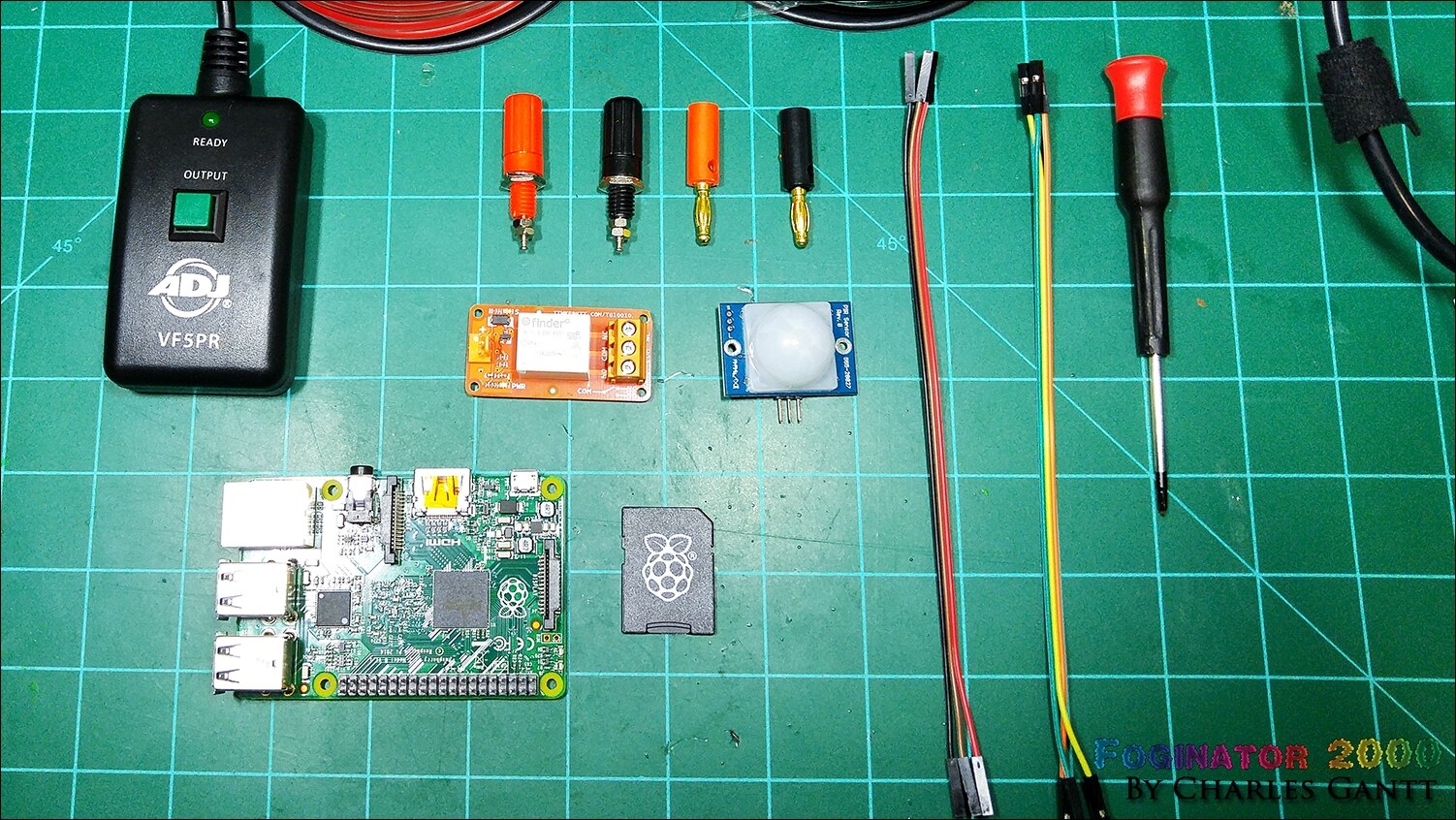
Below is a table containing the parts you will need for this project. In addition to these parts you will need a drill, drill bit, soldering iron, stranded hook up wire, and some female to female jumper wires.
Newark Part No. | Notes | Qty | Manufacturer / Description |
38Y646738Y6467 | RPi | 1 | RASPBERRY PI 2, MODEL B |
38Y647038Y6470 | SD Card | 1 | RASPBERRY PI 8GB NOOBS MICRO SD CARD |
44W493244W4932 | PSU | 1 | USB PORT POWER SUPPLY 5V, 1A |
06W104906W1049 | USB Cable | 1 | USB A PLUG TO MICRO USB B PLUG |
53W628553W6285 | WiFi Dongle | 1 | USB WIFI MODULE |
MCM Part No. | Notes | Qty | Manufacturer / Description |
Relay Module | 1 | TinkerKit Relay Module | |
Fog Machine | 1 | Fog Machine Hurricane 901 | |
Parallax PIR Sensor | 1 | PIR Infared Measurement Sensor Module |
The Theory
The fog machine will trigger when trick-or-treaters trip its motion sensor. Throughout this project we will call this a “trick-or-treat event,” or “T&T Event” for short. So when the T&T event happens, the fog machine to fire off and begin fogging out the immediate area. To do this we need to first take a look at how a fog machine works, and methods to trigger a fog-machine based on motion detection. First we will take a quick look at how a fog machine works.
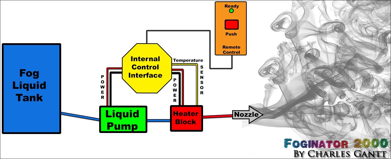
In the image above you can see how the basic operations of a standard fog machine works. Fog liquid is pumped from a reservoir into a heater block, which flashes to a vapor and exits out of a nozzle due to the pressure created by the expanding gasses. Everything is controlled from a central control interface, and depending on the quality and brand, this could be nothing more than a few passive components all the way up to a full scale MCU-based controller.
On most fog machines with manual remotes, a small LED indicator is present that illuminates when the heater block has reached optimal temperature. On the ADJ 1300W that we are using, this LED, as well as the push button are powered by low voltage, but on many fog machines, these components can be powered by mains voltage. Exercise extreme caution and high voltage safety when modifying any fog machine.
So in theory we should be able to use a relay to trigger the fog machine using the wires that go to the push button. As an added bonus we should be able to use the signal from the “ready” led to tell the Raspberry Pi that the fog machine is armed and ready to spray fog. If your fog machine uses high-voltage for its LED, then this will not work, and you will have to design a rectifying solution. So the bulk of this blog post will be showing you how to modify the manual remote control for the ADJ VFI1300 1300W Fog Machine, this method may work on other ADJ fog machine products, but I am not sure. Remember that this will most certainly void your warranty, and you are assuming all risk associated with modifying a product to perform in a way it was not designed to do from the factory. I take on no responsibility if anything should go wrong.
The Schematic
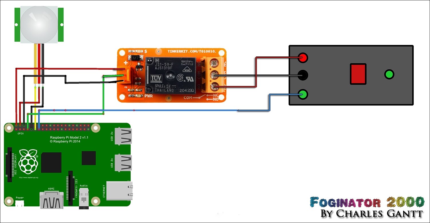
As you can see in the image above, my plan is to utilize the TinkerKit relay module as a sort of “smart” switch to fire the fog machine. The PIR-based motion sensor will be used to sense motion which will tell the Raspberry Pi 2 to trigger the relay. I am using seven of the Raspberry Pi 2’s GPIO pins including both of its 5-volt pins, two of its ground pins, and three actual I/O pins.
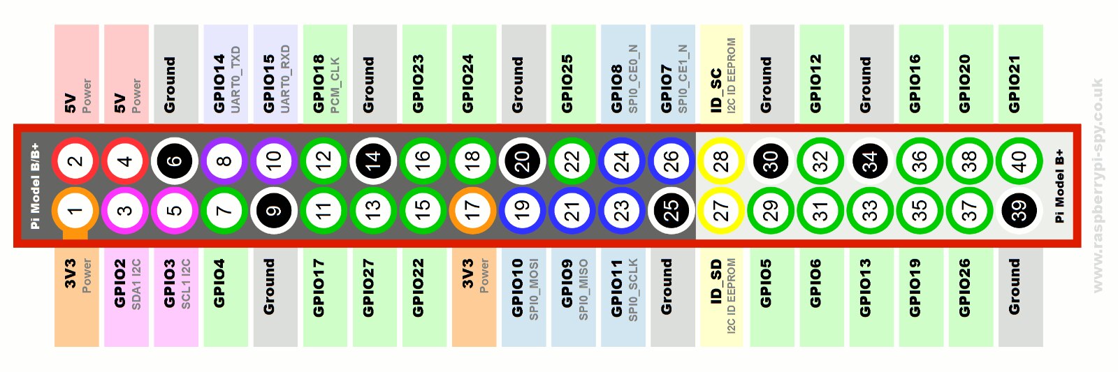
Using the Raspberry Pi 2 GPIO Pinout reference above, you can see that the three I/O pins I am using are (BCM schema)
- Raspberry Pi GPIO4 to TinkerKit Relay Module
- Raspberry Pi GPIO17 to Parallax PIR Motion Sensor
- Raspberry Pi GPIO27 to Fog Machine Remote “Ready” Indicator LED (used in a later project update)
With our schematic planned out, let’s begin the build by modifying the ADJ VFI1300 1300W Fog Machine’s manual remote control. Again, if you are modifying any fog machine’s remote control other than the exact model that I am using in this tutorial, beware that it could utilize mains voltage instead of low voltage. Proceed with caution.
Modifying The Remote
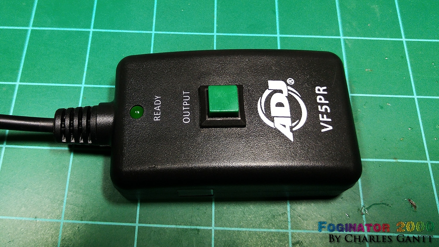
Here we can see the manual remote that came with the ADJ VFI1300 1300W Fog Machine. Notice the “Output” button and the “Ready” LED. These are the objects we will be hacking some wiring to in order to connect them to our Raspberry Pi and TinkerKit relay module.
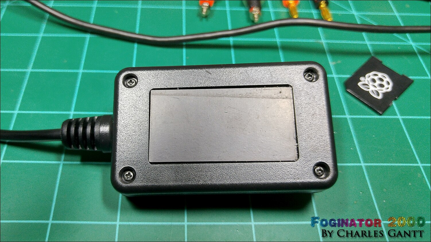
Opening the remote up is quite simple and only requires the removal of four phillips head screws. Save the screws as we will be putting this back together when the modifications are complete.

Once the back has been removed you will see a bundle of wires attached to two leads of the momentary push button and the “ready” indicator LED. To fire the fog machine one simply needs to close the “trigger” circuit by pressing the button. This means that we can easily modify this to utilize a relay to trigger the fog machine. Additionally we can use the low-voltage signal from the indicator LED to tell the Raspberry Pi that the fog machine is armed and ready to fire.
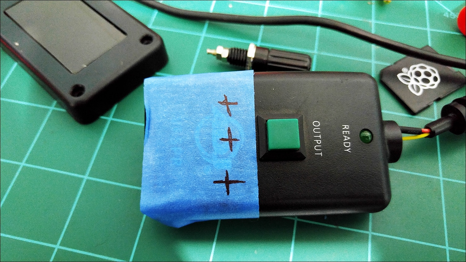
Before we can solder in the wiring, we need to make room to place our three binding post. Since this case is tapered, you need to drill the holes just above the ADJ logo as seen in the image above. Make sure that you space the holes so that all three binding post will fit, and their mounting hardware does not get obstructed by the adjacent binding post’s hardware.
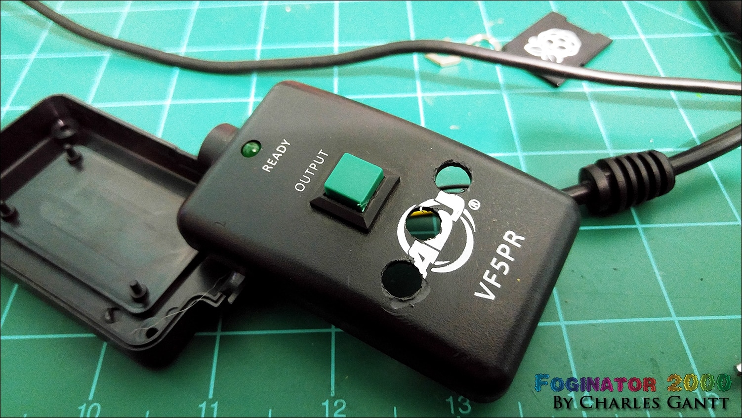
As it turns out, the plastic used in the casing for the remote is quite cheap, and very brittle. I used a brand new, very sharp drill bit to drill a pilot hole, and then a larger one that was just as sharp, and the plastic fractured and flaked in a few places. If this were a proper glass-filled ABS or Nylon case this would not have happened.
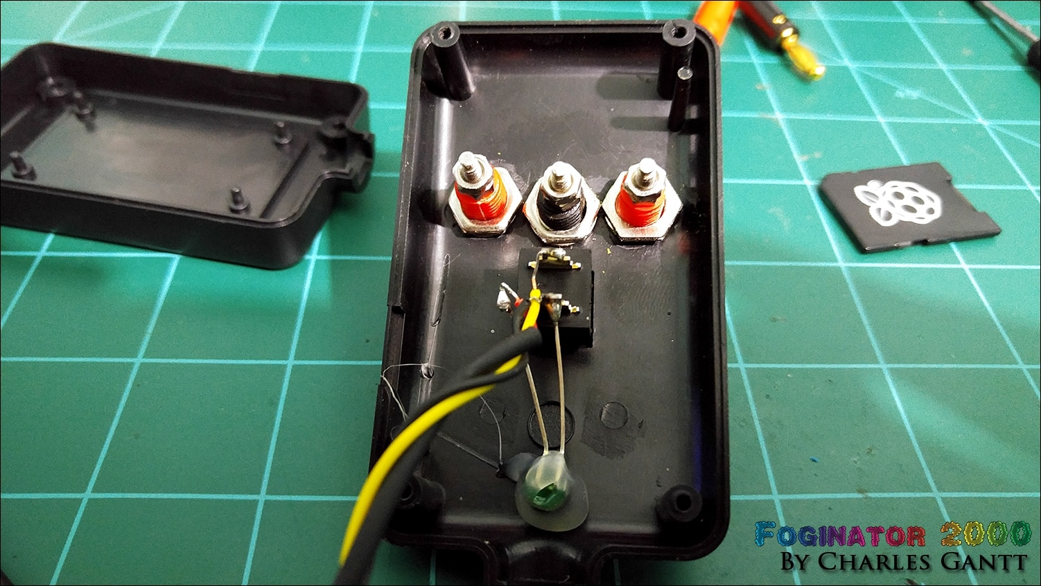
Take notice of how close the nuts are that fasten the binding post to the case. I failed to account for the proper spacing when laying out where to drill the holes, and somehow I got lucky enough that everything just barely fit. I would suggest that you add a dab of CA glue, hot glue or some other adhesive to these nuts as they tend to back off the threads after some time passes.
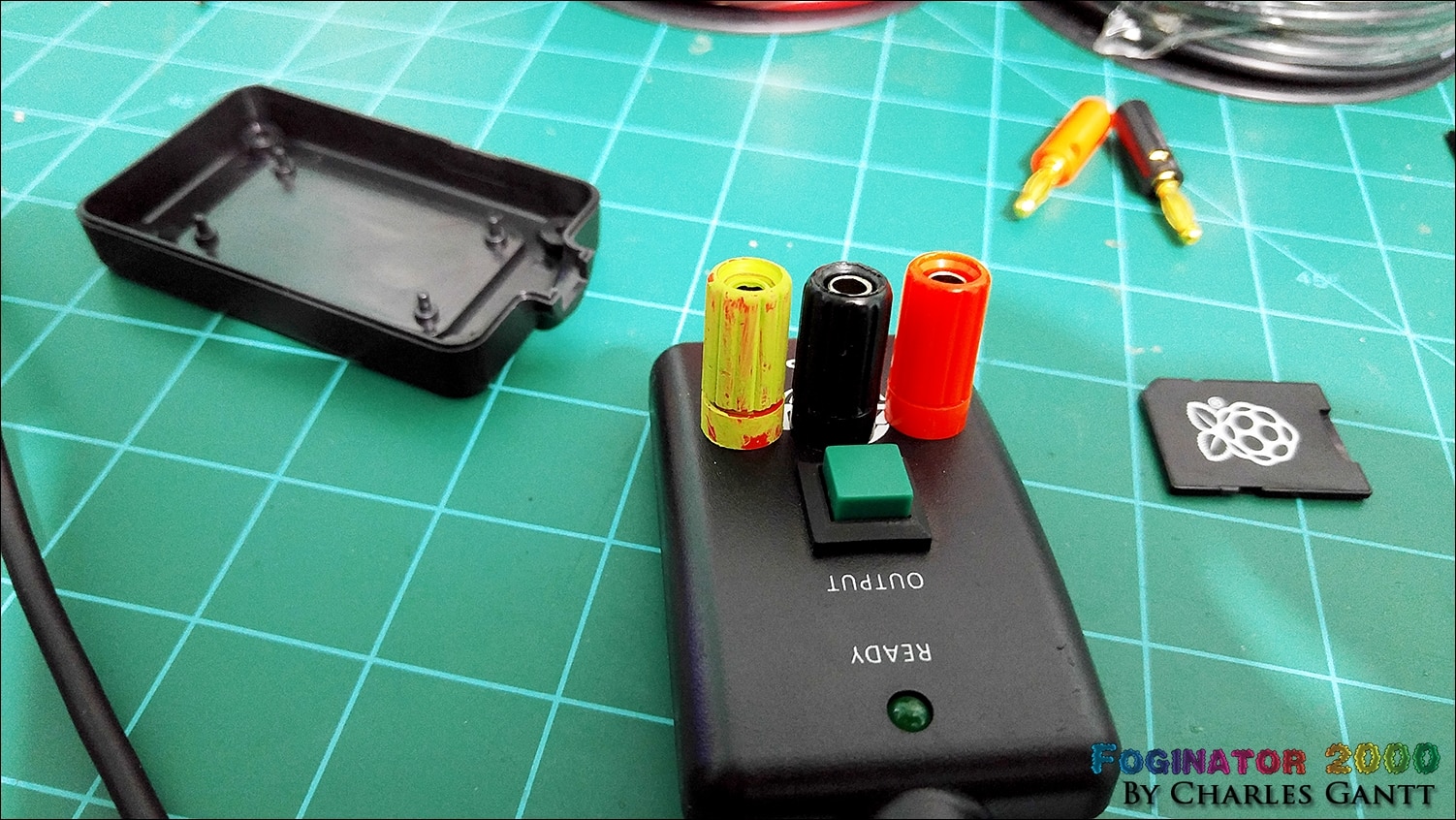
As you can tell, I am not using the binding post I listed in the parts list for this post. I forgot to order the correct ones when I designed the kit, and am using some I found in my scrap parts box. The ugly green binding post was painted with craft acrylic paint from a local hobby store. It did not adhere as well as I wanted, but it serves its purpose of identifying the post as being different.
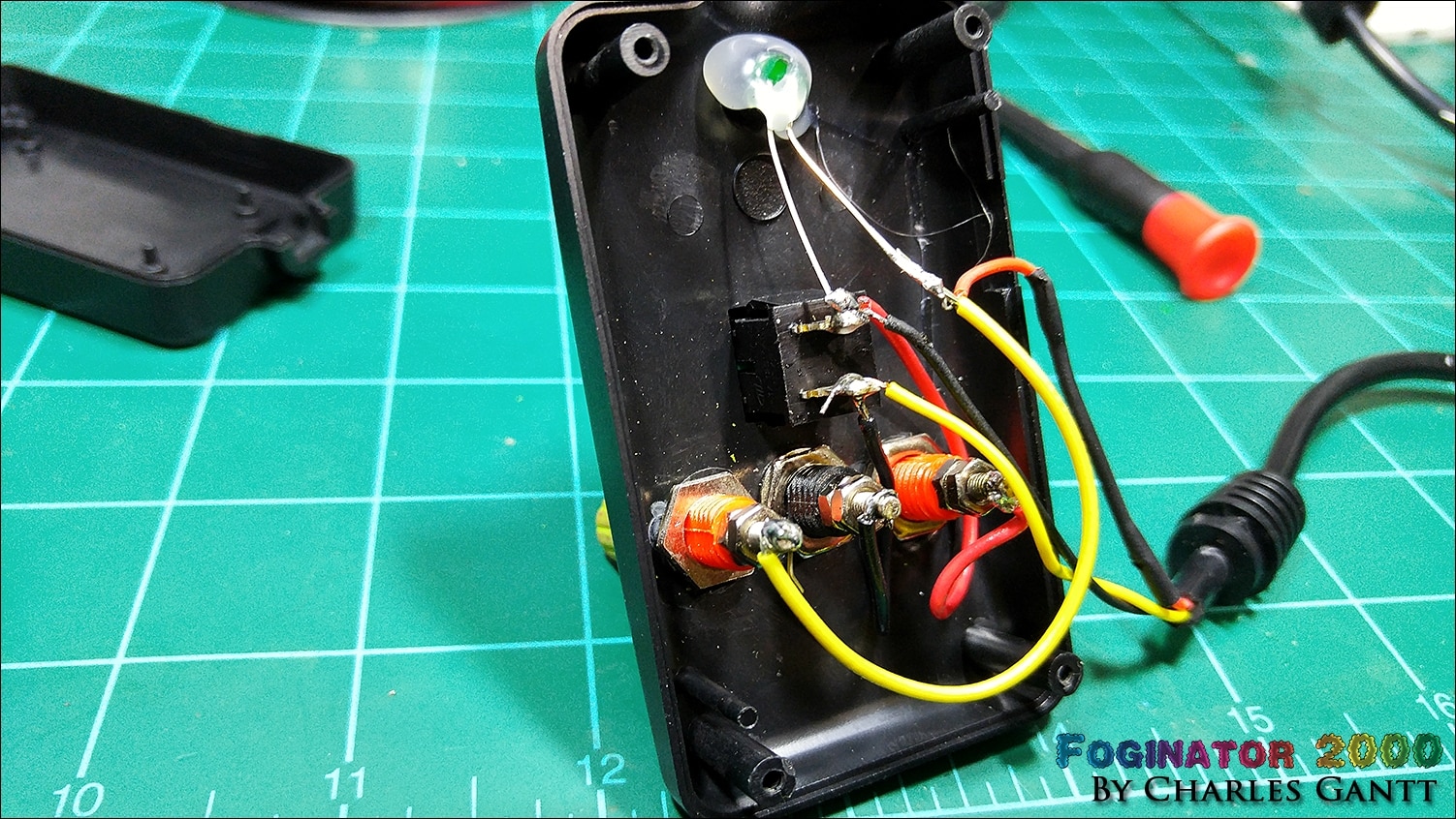
Hacking the switch to work with our relay is super simple. You simply need to solder one of the switches leads to either the red or black binding post, and then solder the other switch lead to the other binding post. While you are in here, solder a wire from the anode side of the LED to the other binding post.
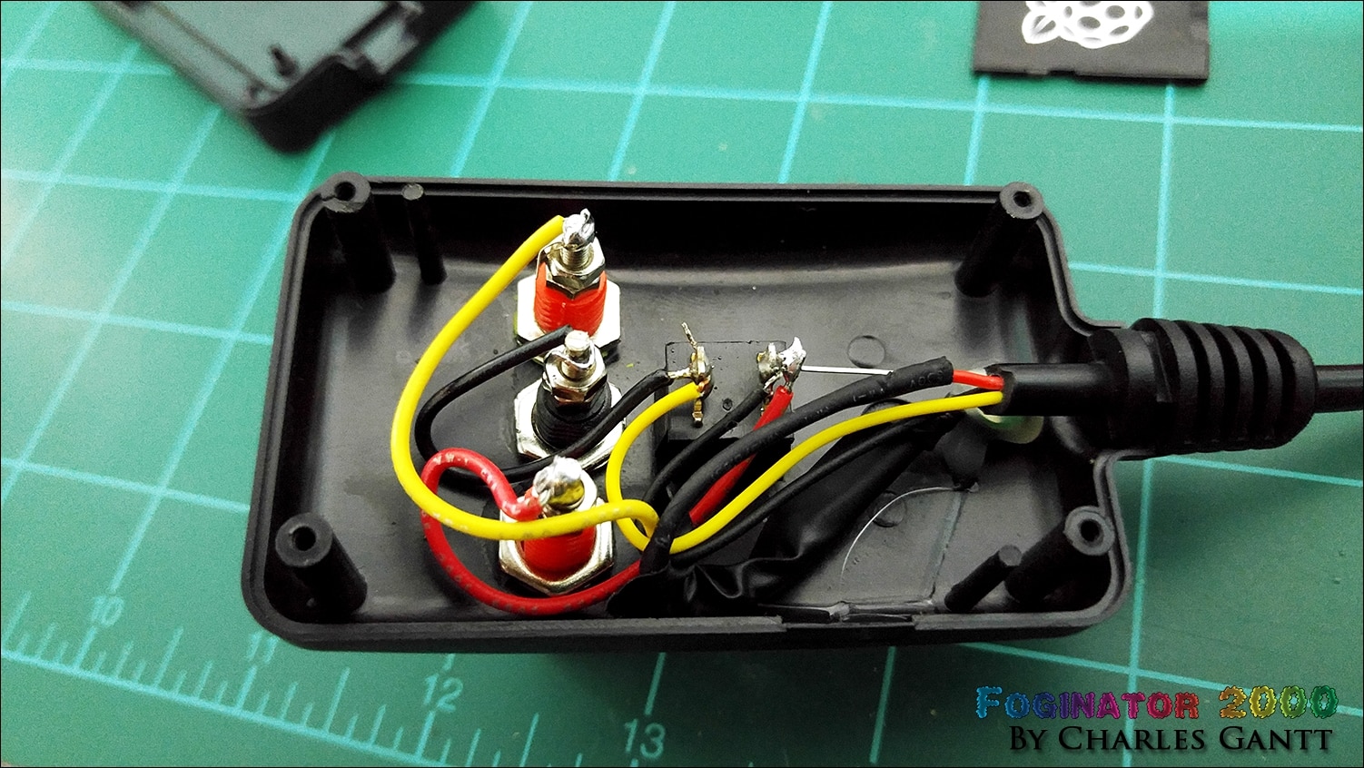
I messed up and accidentally heated the heat shrink on the LED wire with my soldering iron which caused it to no longer slide over the LED’s lead. Instead of cutting it off and adding a new piece in, I simply chose to wrap it in 3M Super 33 Electrical Tape.
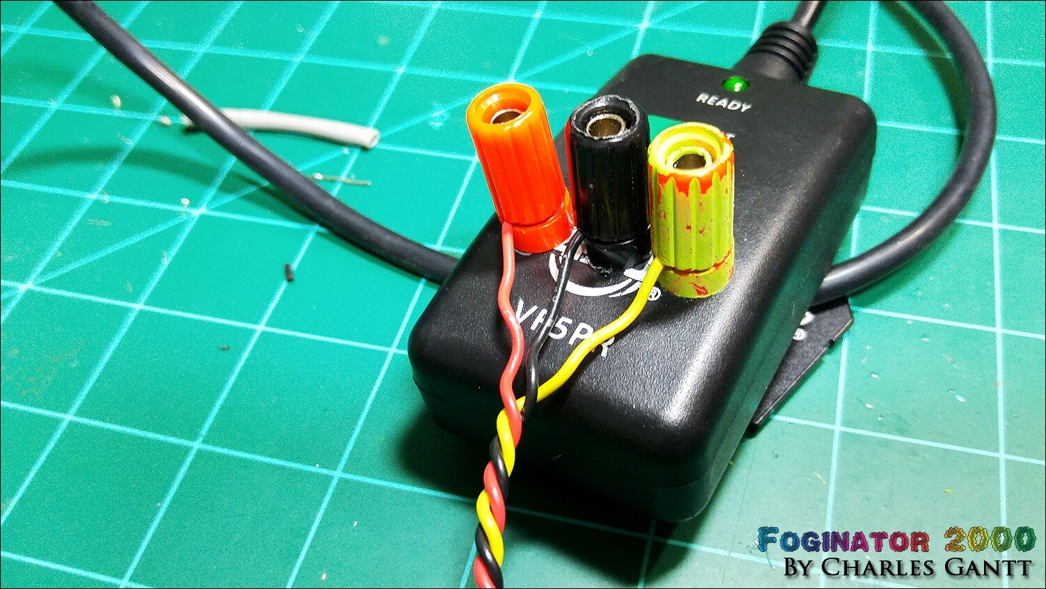
Now simply screw the bottom of the case back on, and then cut three 24” lengths (or longer depending on your needs) of the stranded hook-up wire. I chose to use red, black, and yellow. For a cleaner look, I chucked the wires up in my cordless drill, and twisted them together. I lost a few inches in length because of this, but it looks much cleaner and is easier to manage. Connect the three wires to the binding post as shown in the image above. Red to red, black to black, and yellow to yellow.
Connecting The PIR Motion Sensor
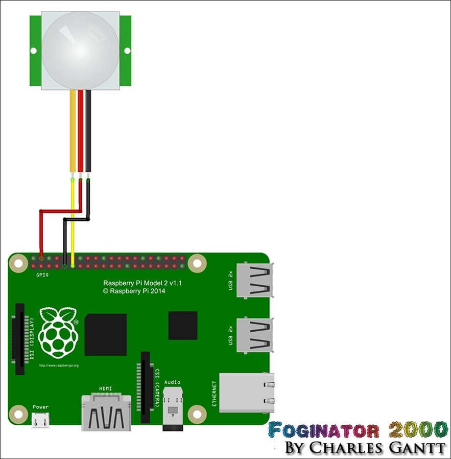
Connecting the Parallax PIR sensor to the Raspberry Pi is quite easy as well, and only requires a few lines of code to test its functionality. To start you will need to connect the PIR sensor to the Raspberry Pi as per the diagram above, following the pinouts below.
- PIR “Out” Pin to Raspberry Pi GPIO17
- PIR “VCC” Pin to Raspberry Pi 5V Pin
- PIR “GND” Pin to Raspberry Pi GND Pin
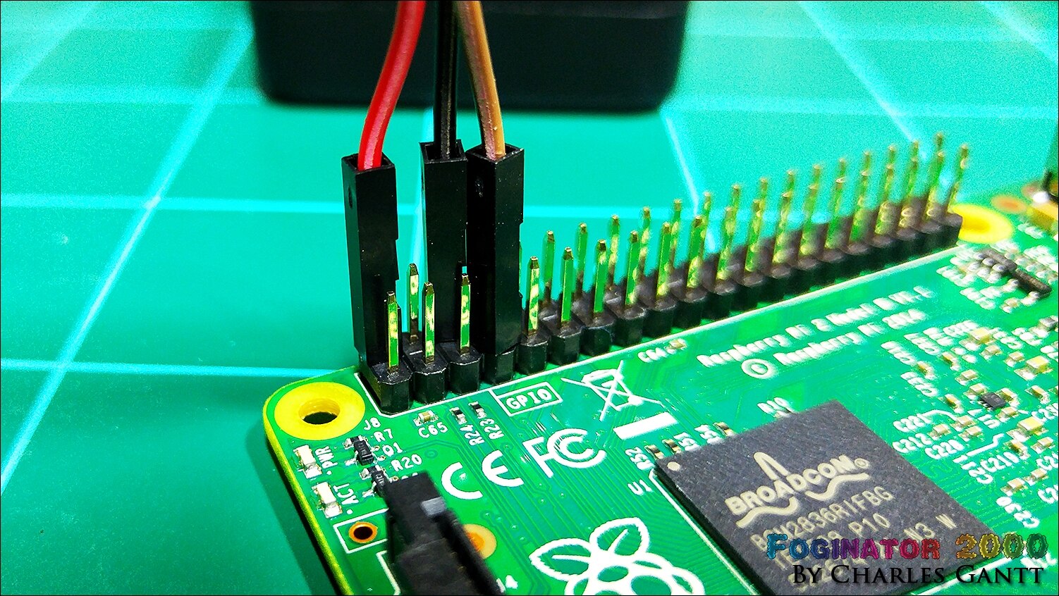
With those connected, you will need to boot up your Raspberry Pi 2 with the NOOBS SD Card installed, or any SD Card with Raspbian installed on it. It is also advisable to update your version of Raspbian to the latest. If you need to learn how to do this, I briefly cover it in part two of my other Halloween Project, Trick or Trivia.
The Code
With everything updated, and the SSH connection still open, type the following command to create a python file for testing the PIR sensor
sudo nano test-pir.py
This will create the file and open it in the nano text editor. Before we paste the python code in, lets take a look at it step by step and what each step does.
We need to import the Raspberry Pi GPIO library, the time library, and the system library. So python can execute our code.
import RPi.GPIO as GPIO
import time
import sys
Now we need to set up our GPIO pin. Note that we are using the BCM schema to run our code. For those of you who do not know, the Raspberry PI’s GPIO pins can be configured two different ways, GPIO.board and GPIO.bcm. When setting the GPIO pins mode, you are telling it what numbering scheme your code will be adhering too. Unfortunately the pin numbering between each of the different modes changes on various models and revisions of the Raspberry PI. So if you are not running a Model B+ or Raspberry Pi 2, you will need to search the internet for the proper pinouts for the mode you select.
The GPIO.BOARD option specifies that you are referring to the pins by the number of the pin the the plug - i.e the numbers printed on the board (e.g. P1) and in the middle of the diagram above.
The GPIO.BCM option means that you are referring to the pins by the "Broadcom SOC channel" number, these are the numbers after "GPIO" in the green rectangles around the outside of the diagram above.
GPIO.setwarnings(False)
GPIO.setmode(GPIO.BCM)
GPIO.setup(4, GPIO.OUT)
GPIO.setup(17, GPIO.IN)
Now we can build a function to test our code. We will call the function fire_fog. The code below it basically says to set GPIO 4 to True (high) for three seconds (triggering the fog machine, then set it to False (stop firing fog), then the code cleans up the GPIO Pins, and exits the script.
def fire_fog():
    GPIO.output(4,True)
    time.sleep(3)
    GPIO.output(4,False)
    GPIO.cleanup()
    sys.exit()
Now we need to tell the to wait for a high signal on GPIO17 (movement detected by the PIR sensor), and to run the fire_fog function if that high signal is present. I put this in a “while” statement so that it would loop over and over until motion is detected. There are better ways to do this, but I am still brushing up on my python.
while 1:
    time.sleep(3)
    if GPIO.input(17)==True:
        fire_fog()
Now past the following lines of code into the file. You can also download this code from it's GitHub Repo. If you are using a terminal such as putty, you can simply copy this code and right click in the terminal to paste it.
import RPi.GPIO as GPIO
import time
import sys

GPIO.setwarnings(False)
GPIO.setmode(GPIO.BCM)
GPIO.setup(4, GPIO.OUT)
GPIO.setup(17, GPIO.IN)

def fire_fog():
    GPIO.output(4,True)
    time.sleep(3)
    GPIO.output(4,False)
    GPIO.cleanup()
    sys.exit()

while 1:
    time.sleep(3)
    if GPIO.input(17)==True:
        fire_fog()
Now save and exit out of the nano text editor. If everything is connected correctly, and the code is correct, we can move onto connecting the TinkerKit relay module to the Raspberry Pi and test our PIR sensor out.
Connecting And Testing The Relay

Now connect the relay as shown in the schematic above, and the pinout below. Only make the Raspberry Pi to Relay connection at this time.
- Tinkerkit Relay + Pin to Raspberry Pi 5V Pin
- Tinkerkit Relay Signal Pin (Middle) to Raspberry Pi GPIO4
- Tinkerkit Relay - Pin to Raspberry Pi GND Pin
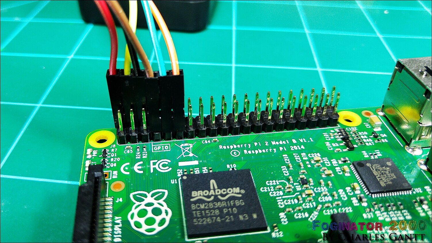
With everything connected, we can now test the PIR and Relay systems. From the terminal, enter the following command:
sudo python test-pir.py
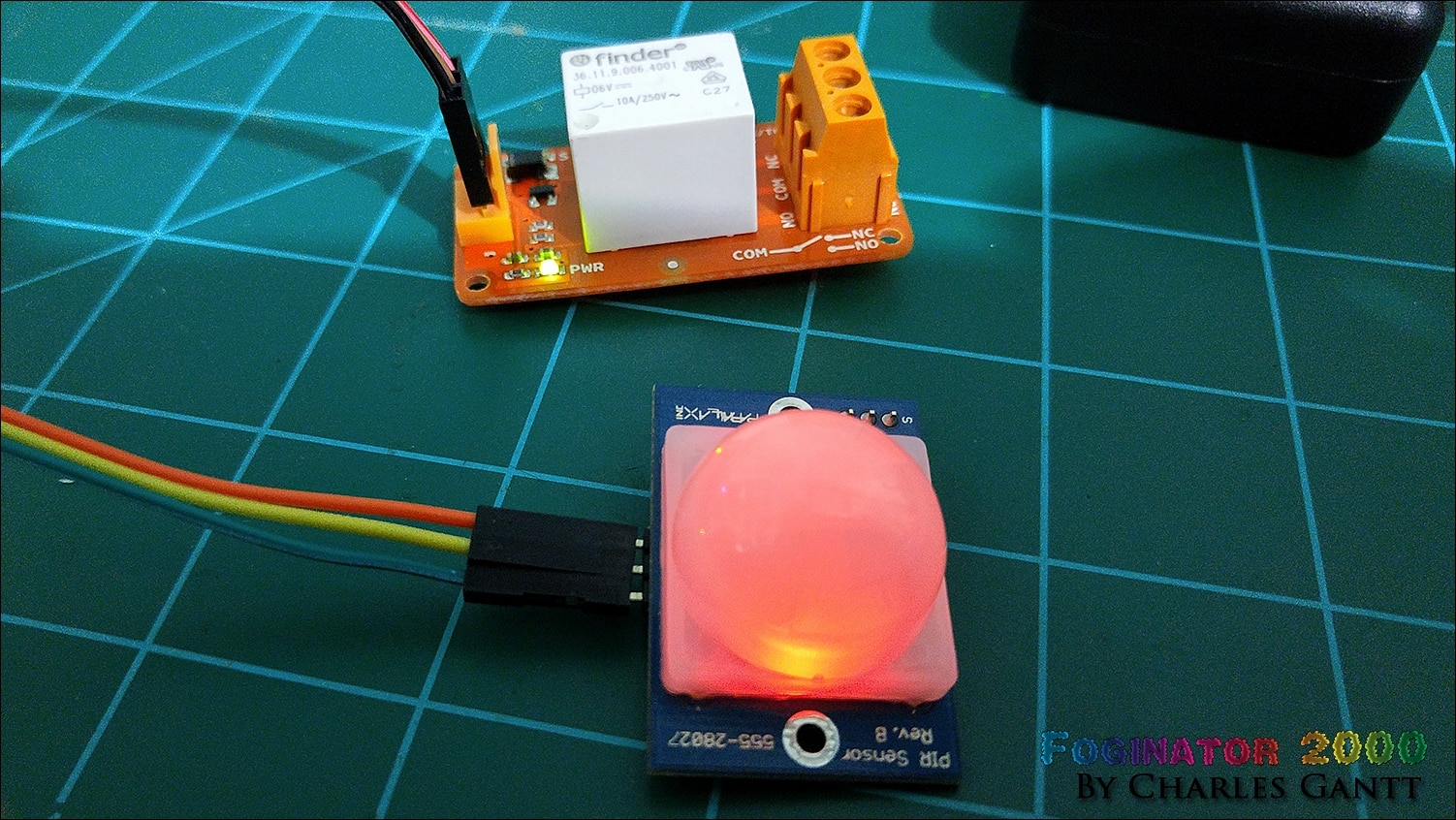
The script will wait a few seconds before looking for motion, so wait a few seconds, and then wave your hand in-front of the sensor. It will illuminate, indicating that motion was detected. If you do not hear the relay click on, then wait a few more seconds and try again. If the click does not happen after waiting for 15 seconds, then check the code again. If the code is working, you will hear the relay click on for three seconds and then click off.
Bringing It All Together
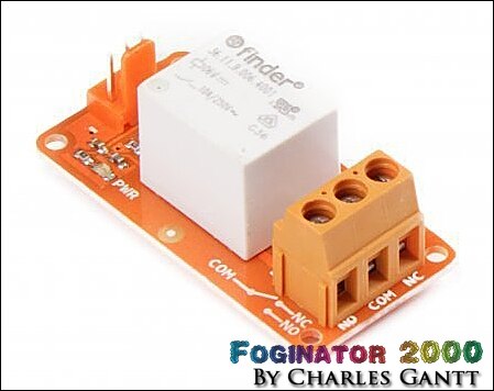
Now connect the red and black wires to the “Comm” (Common) and “NO” (Normally Open) contacts on the relay. Don’t worry about the “ready” (Yellow) wire for the moment. We will revisit it in another post.
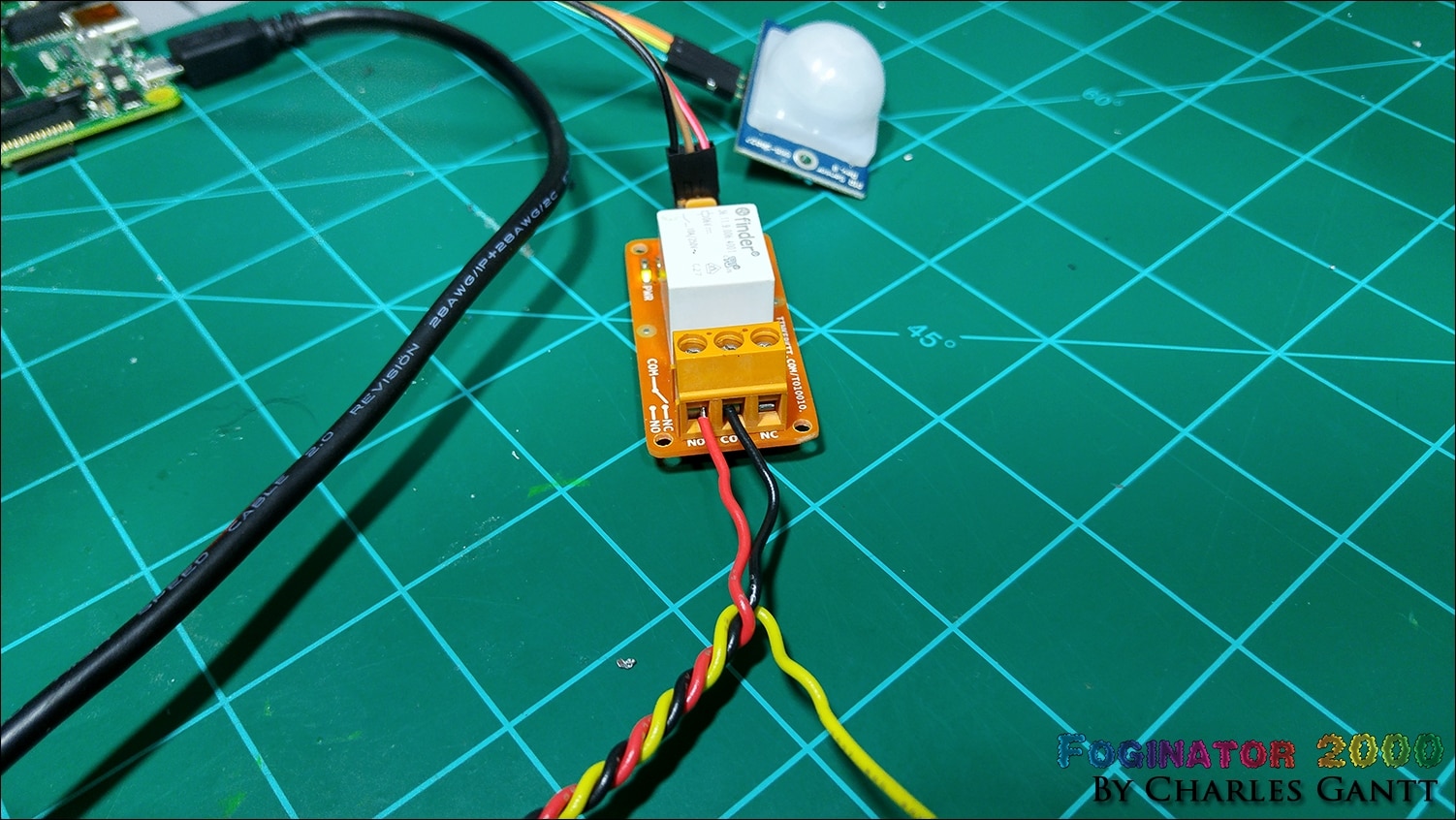
If you have not filled the fog machine with fog juice yet, now would be the time to do so. (I recommend Hog Fog as it is super clean, thick, low-lying, and have used it personally many times!) With everything connected you can connect the remote’s cable to the fog machine, and then connect the fog machine to the mains supply. Switch the fog machine on, and wait for about 5 minutes for the green light to come on. The run the script again from the terminal.
sudo python test-pir.py
If everything is correct, then the PIR sensor should begin looking for motion three seconds after the script has been triggered. These three seconds allow for you to get out of the way when setting the Foginator2000.
That is going to end it for this installment of Project: Foginator2000! Tune in next week for installment 3, in which I work on the environment sensing coding & testing aspect of the project. If you have not yet seen my other Halloween project for 2015 here at Element14, head over to Trick or Trivia: A trivia-based Halloween Candy Dispenser - Part 001. Until next time, remember to Hack The World and Make Awesome!
- Project Introduction
- Fog Controller Hardware and Test
- Environment Sensing Coding & Testing
- Ambient Audio Hardware and Coding
- Lighting Coding and Testing
- October 16th - Final Assembly and Testing
- October 23th - Project Wrap-up
Originally published by Charles Gantt on Element14 Community
Part 3: Foginator 2000: #003 Raspberry Pi Sense Hat Integration with Initial State

Welcome to installment #003 of Project: Foginator 2000 part of the 2015 Raspberry Pi Halloween Project series here at Element14. In this week's episode I am going to cover the basics of getting the Raspberry Pi Sense HatRaspberry Pi Sense Hat up and running, and a very light tutorial on how to push this data to the cloud in order to record and analyze the data. The cool thing about this is that we can simply save all of our acquired data to the cloud, and access it from anywhere!
The Hardware
Below is a table containing the parts you will need for this segment of the project. In addition to these parts you will need to connect the Raspberry Pi to the internet either via a wifi dongle, or a wired Ethernet connection.
Newark Part No. | Notes | Qty | Manufacturer / Description |
38Y646738Y6467 | RPi | 1 | RASPBERRY PI 2, MODEL B |
38Y647038Y6470 | SD Card | 1 | RASPBERRY PI 8GB NOOBS MICRO SD CARD |
44W493244W4932 | PSU | 1 | USB PORT POWER SUPPLY 5V, 1A |
06W104906W1049 | USB Cable | 1 | USB A PLUG TO MICRO USB B PLUG |
53W628553W6285 | WiFi Dongle | 1 | USB WIFI MODULE |
| 49Y756949Y7569 | RPi Sense Hat | 1 | Raspberry Pi Sense HAT |
The Theory
The idea behind this part of the project is to log environmental data from the immediate area surrounding the fog machine. Using the Raspberry Pi Sense Hat we will measure and log temperature, humidity, and barometric pressure, and then push it up to the cloud. We will trigger this data logging even every time the fog machine trips, and will record the entire event as a “Trick-Or-Treat Event.” Then we will be able to export the data as a CSV file and analyze what temperatures, humidity levels, and barometric pressure levels correlated with spikes in Trick-Or-Treat events.
For the purpose of this blog post, we will be simply figuring out how to read the data from the Sense Hat with our Raspberry Pi. Once we have that figured out we can move on to learning how to push that data to the cloud.
The Sense Hat

The new Raspberry Pi Sense Hat was released a few weeks ago, and to be quite honest, I had planned this project out before it was released, and I was quite confused as to what this Hat actually did. The Sense HAT is an add-on board for Raspberry Pi, made especially for the Astro Pi mission that will be performed on the International Space Station in December 2015.
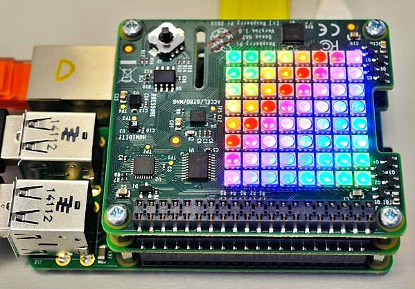
The Sense HAT has an 8×8 RGB LED matrix, a five-button joystick and includes the following sensors:
- Gyroscope
- Accelerometer
- Magnetometer
- Temperature
- Barometric pressure
- Humidity
To make things simple, the Raspberry Pi Foundation has created Python library providing easy access to everything on the board. You can find that library here.
Installing Astro Pi / Sense Hat

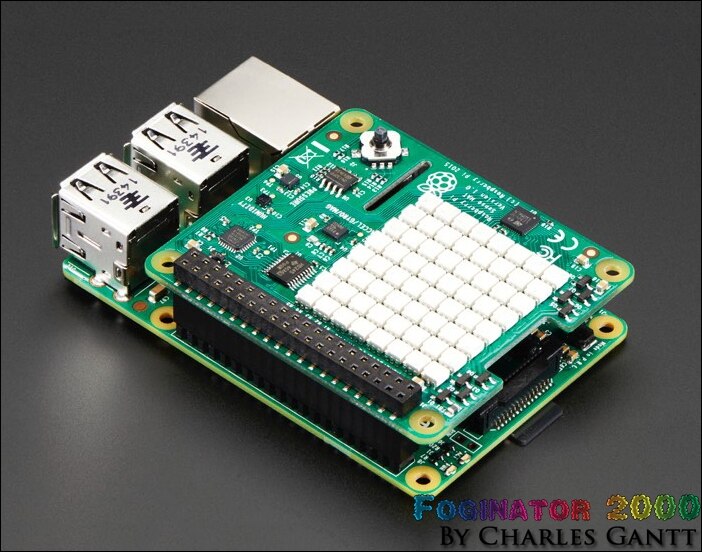
To get started you need to connect the Sense Hat to a Raspberry Pi 2 by placing it on the GPIO Pins. Note the orientation of the board in the image above.
Now we need to install the Raspberry PI Sense Hat library package into Raspbian. So SSH into the Raspberry Pi, or open the terminal if you are using your Pi with a Monitor such as the new Raspberry Pi 7-Inch Touch Screen. If you are following along at home, and building your own Foginator, your Raspbian install should already be updated, but just incase run the following commands in the terminal.
sudo apt-get update
sudo apt-get upgrade -y
Then run the following command which will download the necessary package to get the Sense Hat up and running. This process should take less than five minutes on a Raspberry Pi 2, but it could take longer. Do unplug your Raspberry Pi during this process.
sudo apt-get install sense-hat
Then to finish up the process you need to restart the Raspberry Pi. To do this, run the following command.
sudo reboot
Once the Pi has had time to reboot, reconnect via SSH or re-open the terminal.
Testing AstroPi and The Sense Hat

Let’s create a quick Python script to test that everything was installed and connected correctly. Using the Nano text editor, create a new file named sense_test.py. You can do this with the command below.
sudo nano sense_test.py
Now copy and paste the script below. This script basically tells the sense hat to scroll the words “Hello World” across the Hat’s LED matrix. When you have the code pasted, exit out of nano while keeping the same file name.
from sense_hat import SenseHat
sense = SenseHat()
sense.show_message("Hello World")
Now enter the command below to run the script we just created.
sudo nano sense_test.py
Now you should see Hello World scroll across the LED matrix. If this works, you are ready to move onto the next step. If not, something went wrong with your install of Astro Pi. Go back over the steps to make sure everything is installed and written correctly.
Acquiring Data From The Sense Hat
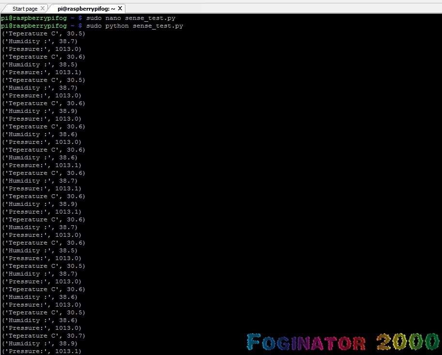
Following some excellent tutorials on the RaspberryPi.org website, I was able to quickly get data from the temperature, air pressure, and humidity sensors. Surprisingly, this is possible with only a handful of lines of Python code. Below is a breakdown of the code and what each line / section does.
First need to import the sense_hat library, the time library, and the system library.
from sense_hat import SenseHat
import time
import sys
Now we need to initialize the sense hat, and clear its matrix.
sense = SenseHat()
sense.clear()
Now we need to set a variable named var, and give it a value of 30. This is used to close the program after it loops for 30 cycles.
var = 30
Now we need to create our while loop, and set it to run if var is greater than 0.
while var > 0:
The first data we want to import is the ambient temperature. The Sense Hat library makes this super simple, and all we have to do is tell the program to get the temperature. The default output is in degrees celsius, and is extended to several places after the decimal.
temp = sense.get_temperature()
To round that number to a more friendly tenth of a degree, we can simply tell the program to round the temperature output to the first decimal place.
temp = round(temp, 1)
Now we can print our temperature to the terminal. To do this we simply write a print command, and write some text to explain what this output is so that other people can understand what they are reading.
print("Teperature C",temp)
The same methods apply to the humidity and pressure readings as well, so I won’t list each of them out line by line.
  humidity = sense.get_humidity()
  humidity = round(humidity, 1)
  print("Humidity :",humidity)
  pressure = sense.get_pressure()
  pressure = round(pressure, 1)
  print("Pressure:",pressure)
Now we need to tell the program to wait for one second before continuing on. This slows down the rate at which the data is read and output. You can slow this rate down by increasing the number after the time.sleep command, or you can speed it up by decreasing the number.
time.sleep(1)
Now we need to tell the program to decrease the var variable by one.
var = var -1
With our var variable decreased by one, we need to check to see if it has reached 0 yet. If it has, we can tell the program to exit. This allows us to poll data for as long as we want, and not have the loop constantly running. Basically the while loop will run over and over until the var variable has decreased to 0.
  if var == 0:
    sys.exit()
Putting It All Together
Below is the full code we just wrote, without any comments. Nano into the sense_test.py file and delete all of the code that is in it. Then copy and paste the code below, and save the file.
from sense_hat import SenseHat
import time
import sys

sense = SenseHat()
sense.clear()

var = 30

while var > 0:
  temp = sense.get_temperature()
  temp = round(temp, 1)
  print("Teperature C",temp)
  humidity = sense.get_humidity()
  humidity = round(humidity, 1)
  print("Humidity :",humidity)
  pressure = sense.get_pressure()
  pressure = round(pressure, 1)
  print("Pressure:",pressure)
  time.sleep(1)
  var = var -1
  if var == 0:
    sys.exit()
Now run the program we just wrote with the following command:
sudo python sense_test.py
You should see each data set we are looking for, temperature, humidity, and pressure being displayed in the terminal. The Raspberry Pi will poll and display the data for 30-seconds / loops if you stuck with the 1-second delay we wrote into the while statement. With that working, lets move on to getting this data into the cloud.
Pushing The Data To The Cloud / Internet Of Things

A while back I received an email from a company called Initial State who wanted me to try out their new cloud-based data visualization solution that is geared towards makers, and programmers alike. Unfortunately I forgot all about Initial State due to some life events taking me away from making things for a few months. I had not thought about Initial State for months until I was writing up one of my Design Challenge Summaries, and wrote about Rick Reynolds’ (RWReynolds) project, Vertically Oriented Modular System. In a comment, Rick mentioned that he used Initial State to record and log the data from his project, and I decided to use it for mine as well.
You will need to go to InitialState.com and signup for a free account. I have a pro-account, but that is because I plan on using it in a lot of my future projects, but the free account should suffice for most.

I won’t go into the whole process of installing Initial State’s logger onto your Raspberry Pi, as Initial State has an excellent video tutorial on how to do exactly that. They also have a very comprehensive written tutorial on the subject as well. You can find the video below, it’s about an hour long, for the full tutorial, but the first 20 minutes should give you a good understanding of how to make this work.
Now let’s modify our code to enable it to begin sending data to the InitialState Cloud. So this by using the Nano text editor to edit the sense_test.py script.
This time around we need to import the InitialState Streamer library as well.
from sense_hat import SenseHat
import time
import sys
from ISStreamer.Streamer import Streamer
Now we need to set up the InitialState Logger, name the bucket for this project, and then enter your access key. Chage the code below to include your key.
logger = Streamer(bucket_name="Sense Hat Environment Stream", access_key="YOUR_KEY_HERE")
Our Setup stays the same
sense = SenseHat()
sense.clear()
var = 30
Now everywhere we told the program to print the output of a sensor, we need to change that to tell the program to log and send that data to the InitialState bucket we created earlier in the code. Everywhere you wrote “print” before, change it to logger.log.
while var > 0:
  temp = sense.get_temperature()
  temp = round(temp, 1)
  logger.log("Teperature C",temp)
  humidity = sense.get_humidity()
  humidity = round(humidity, 1)
  logger.log("Humidity :",humidity)
  pressure = sense.get_pressure()
  pressure = round(pressure, 1)
  logger.log("Pressure:",pressure)
  var = var -1
  time.sleep(30)
  if var == 0:
    sys.exit()
Bringing It All Together
The full code is below.
from sense_hat import SenseHat
import time
import sys
from ISStreamer.Streamer import Streamer


logger = Streamer(bucket_name="Sense Hat Environment Stream", access_key="zLahwAUqKbNKv6YvuT5JuO58EiUOavDa")


sense = SenseHat()
sense.clear()
var = 30


while var > 0:
  temp = sense.get_temperature()
  temp = round(temp, 1)
  logger.log("Teperature C",temp)
  humidity = sense.get_humidity()
  humidity = round(humidity, 1)
  logger.log("Humidity :",humidity)
  pressure = sense.get_pressure()
  pressure = round(pressure, 1)
  logger.log("Pressure:",pressure)
  var = var -1
  time.sleep(30)
  if var == 0:
    sys.exit()
With the script edited and saved, run it using the command below.
sudo python sense_test.py
Now you can go to your InitialState account and click on the bucket you just created to see the data. Remember that IntialState free accounts have a very limited amount of events you can stream each month. Each data point is one event. So running this script in its current configuration would create three events per second for thirty seconds, totaling out at 90 events each time its ran.

I wanted to set this up to read data for several days, and I am one of those kinds of people who need a visual indicator to tell me that things are working as they should. So I once again modified the code to not only run the loop for several days, but also tossed in a few lines that would display a creeper head from MineCraft on the LED matrix at the end of every data collection cycle. If you are interested, that code is below. I won’t go into how I did it, but you can learn more at this link from the Raspberry Pi Foundation.
Code With Creeper Head Appearing On LED Matrix
from sense_hat import SenseHat
import time
import sys
from ISStreamer.Streamer import Streamer


logger = Streamer(bucket_name="Sense Hat Environment Stream", access_key="zLahwAUqKbNKv6YvuT5JuO58EiUOavDa")


sense = SenseHat()
sense.clear()
var = 14400


O = (0, 255, 0) # Green
X = (0, 0, 0) # Black


creeper_pixels = [
    O, O, O, O, O, O, O, O,
    O, O, O, O, O, O, O, O,
    O, X, X, O, O, X, X, O,
    O, X, X, O, O, X, X, O,
    O, O, O, X, X, O, O, O,
    O, O, X, X, X, X, O, O,
    O, O, X, X, X, X, O, O,
    O, O, X, O, O, X, O, O
]


black_pixels = [
    X, X, X, X, X, X, X, X,
    X, X, X, X, X, X, X, X,
    X, X, X, X, X, X, X, X,
    X, X, X, X, X, X, X, X,
    X, X, X, X, X, X, X, X,
    X, X, X, X, X, X, X, X,
    X, X, X, X, X, X, X, X,
    X, X, X, X, X, X, X, X
]


while var > 0:
  temp = sense.get_temperature()
  temp = round(temp, 1)
  logger.log("Teperature C",temp)
  humidity = sense.get_humidity()
  humidity = round(humidity, 1)
  logger.log("Humidity :",humidity)
  pressure = sense.get_pressure()
  pressure = round(pressure, 1)
  logger.log("Pressure:",pressure)
  var = var -1
  logger.log("Seconds Until Script Exit",var)
  sense.set_pixels(creeper_pixels)
  time.sleep(5)
  sense.set_pixels(black_pixels)
  time.sleep(25)
  sense.clear()
  if var == 0:
    sys.exit()
Run this code by using the command below. Note the “&” on the end. This tells the Raspberry Pi to run the script in the background and return the command prompt in the terminal. This allows you to continue developing on your Pi while the script runs. Also note that this means that if the Pi loses power, or you reboot it, the script will stop and you will need to re-run it. You can get around this by setting the script to run on startup. A good tutorial on how to do this can be found at the following instructable. Additionally, you can download all of the code used in this project from it's Github repo.

If you would like to see the data in real time, that my Raspberry Pi / Sense Hat combo is generating, visit the following link or click the image above.
So that wraps up part 3 of the Foginator2000 project. This was a really fun portion of the project for me as I got to learn how easy it is to push data to InitialState, as well as how easy it is to use the Raspberry Pi Sense Hat. Hats off to the AstroPi team, and the Raspberry Pi Foundation for creating such a feature-rich and easy to use Pi Hat. Tune in in just a few days for my next installment on the Foginator2000 project. Until then remember to Hack The World and Make Awesome!
- Project Introduction
- Fog Controller Hardware and Test
- Environment Sensing Coding & Testing
- Ambient Audio Hardware and Coding
- Lighting Coding and Testing
- October 16th - Final Assembly and Testing
- October 23th - Project Wrap-up
Originally published by Charles Gantt on Element14 Community
Part 4: Foginator 2000: #004 Ambient Audio Hardware and Coding

With the month of October almost here, I have kicked these Halloween projects into high-gear. I previously said that update number four would be all about lighting, but since I just finished the audio portion of Project Trick or Trivia, I thought this would be a good time to tackle the audio portion of Foginator2000. Since Trick or Trivia will be playing triggered audio events based on the buttons, I did not want to muddy the dynamic sound-stage with too much audio. So Foginator 2000 will only be playing ambient audio. I may go back and add in a single triggered event with some sort of greeting that would play either when the fog triggers, or right after it finishes. In this update, I am going to show you how I managed to get the audio portion of this project up and running.
If you follow my Trick or Trivia project, you will find that much of this installment is the same. This is because the audio needs for both projects are quite similar, and I did not feel the need to reinvent the wheel for this update. With that said, I had originally planned on running the background / ambient audio from within the same python script that the main program was in, but I slowly realized that this was not needed. After several hours of experimentation with the audio on project Trick or Trivia, I decided that the best route to take for always-on, ambient audio was to create a separate python script that would play the ambient audio loop when the Raspberry PiRaspberry Pi booted up.
The Hardware
Below you will see a list of the hardware used to build out the audio portion of this project. In addition to these components, you will need the following tools: a soldering iron, solder, flush cutters, wire strippers, 3-10 feet of 2-pair cable, and a 6-inch or longer 3.5mm to 3.5mm audio extension cable.
Newark.com
Newark Part No. | Notes | Qty | Manufacturer / Description |
38Y646738Y6467 | RPi | 1 | RASPBERRY PI 2, MODEL B, |
38Y647038Y6470 | SD Card | 1 | RASPBERRY PI 8GB NOOBS MICRO SD CARD |
44W493244W4932 | PSU | 1 | POWER SUPPLY 5V, 1A |
06W104906W1049 | USB Cable | 1 | USB A PLUG TO MICRO USB B PLUG |
53W628553W6285 | WiFi Dongle | 1 | ADAFRUIT USB WIFI MODULE |
40P118440P1184 | Speaker | 1 | VISATON SPEAKER, 20 kHz, 8OHM, 4W |
| 49Y171249Y1712 | 7-Inch Touch Screen | 1 | Raspberry Pi 7" Touch Screen Display |
MCM Electronics
MCM Part No. | Notes | Qty | Manufacturer / Description |
Audio Amp | 1 | Audio Amplifier Kit 2 X 5W RMS |
Building the Velman 2x5W Amplifier
One of the major things that I have learned from being in the Haunted Attraction industry is that lighting and sound are two of the biggest “make it or break it” features of a successful prop. When I was putting together the kit for this project, I knew I wanted audio to be a big part of the project. The Raspberry Pi makes it quite easy to add audio to a project, but unfortunately, unless your project makes use of earbuds, you will need to add an amplifier to the project to drive more powerful speakers.
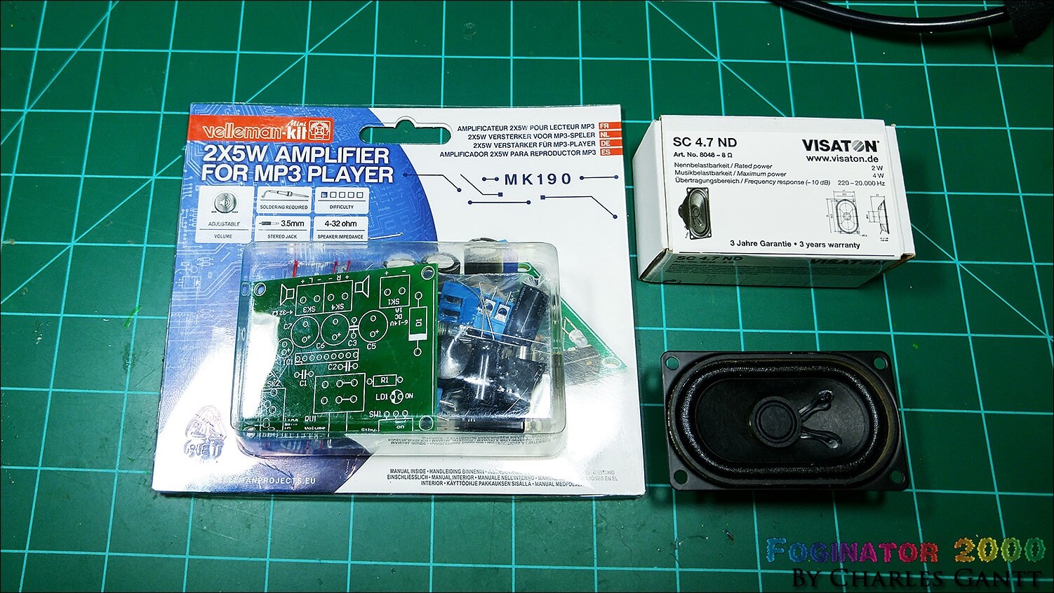
For this project, I chose the Velleman 2x5W Amplifier kit from MCM Electronics. This kit is designed for even the most novice maker to be able to assemble, and it’s quite powerful for its small size. I also chose to use a single small three-inch, eight-Ohm speaker from Visatoneight-Ohm speaker from Visaton. This speakers is a little undersized for this project and this amp, but it works just fine as long as you do not max out the amp’s volume control.
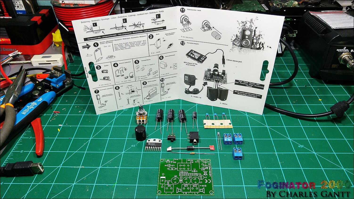
The kit is very straight forward, does not include any confusing, hard-to-identify parts, nor does it utilize any SMD parts that would make it hard to solder. The toughest part to solder in the whole kit is the power indicator LED, as you need to bend it at a very specific point if you want to follow the build instructions 100% word-for-word. I built this entire board in less than 10 minutes.
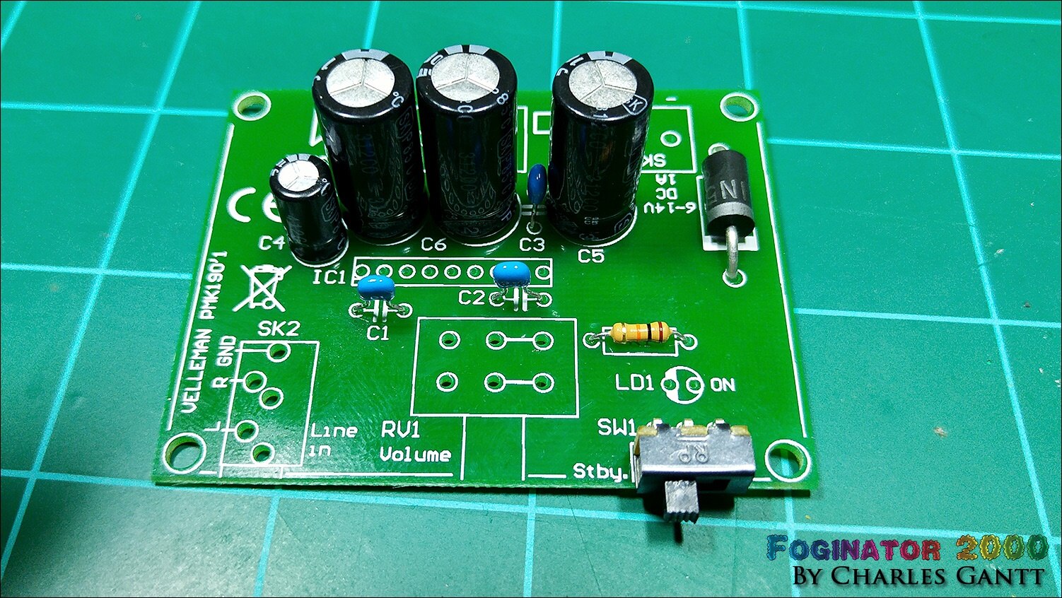
I sort of went off script and soldered up several of the amp’s components at once. If you follow the directions, you will solder each type of component step by step. This was way to slow for me, and I have hand soldered so many SMD boards in the past few months, that I can solder a through-hole board like this with my eyes closed.
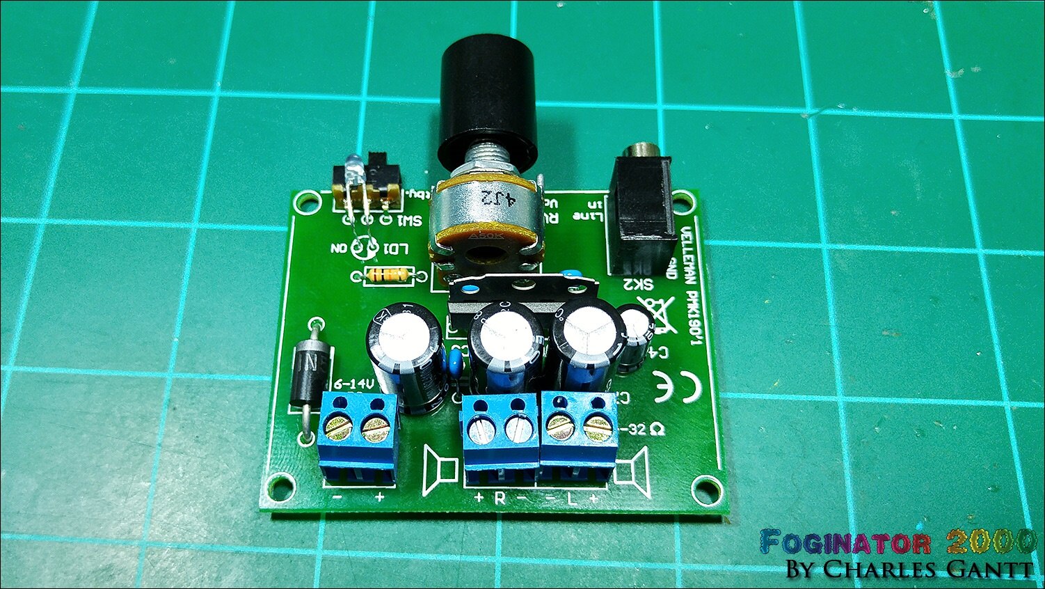
I finished up the board with a second round of soldering. This time I soldered the IC, and other large / heavy components. When soldering terminal blocks, ICs, and other components that are hard to keep in place, or that have several leads, I like to solder one of the leads on an end of the component first. This lets me lock the component in place, then I can use my fingers to re-align the part while re-heating that single solder joint.
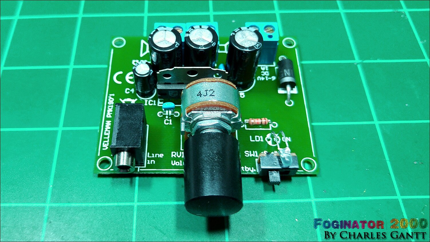
It’s hard to see in this photo, but I set the potentiometer all the way to the left, then placed the knob on it with the indicator dot down in the bottom left corner. This will place the dot almost perfectly opposite this position when the volume is turned to max.
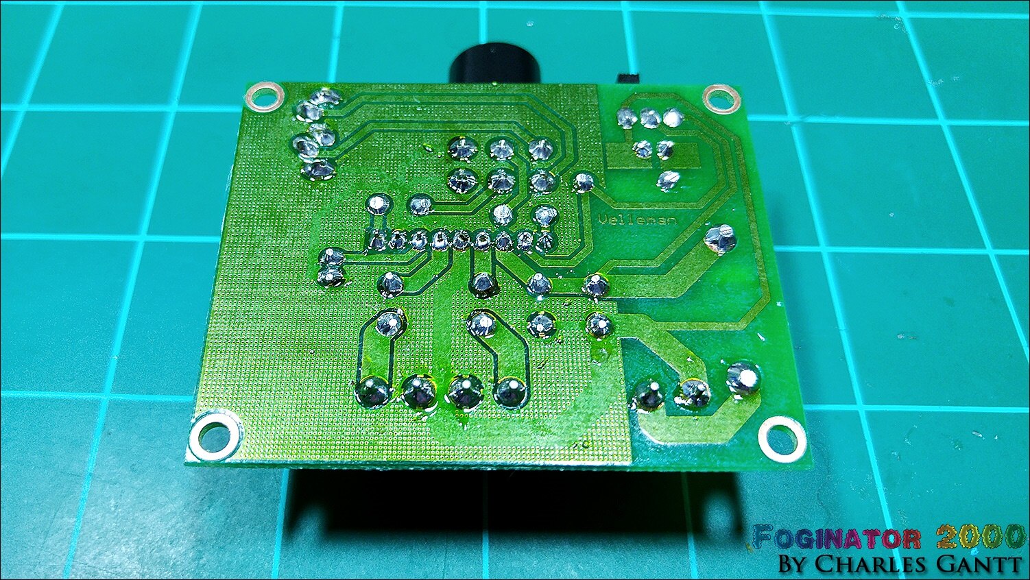
The one thing I always say about soldering is that flux is your friend. Velleman must know this as well because they coated the entire bottom of the PCB in a very sticky resin-based flux. I still used my flux pen on a per-joint basis as I like flux on the component leads I am soldering as well.
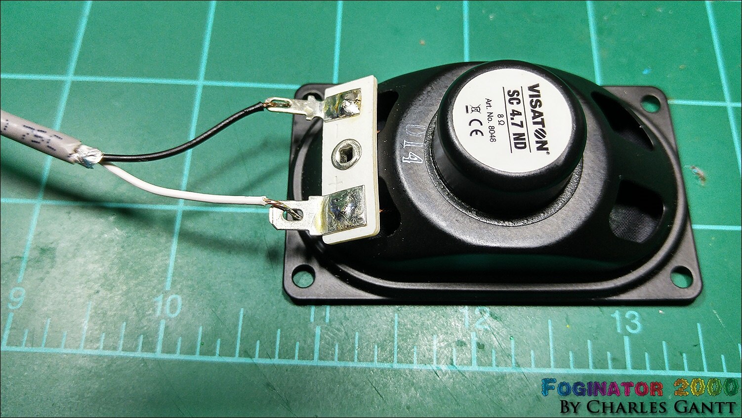
Wiring up the speaker is pretty straight forward as Visaton was kind enough to mark the leads with + and - symbols to identify its leads. For those wondering, the + lead is almost always the larger of the two leads. Rumor has it, that this was adopted as common practice first in the automotive industry back in the 1970s. You will note that I used some spare two-conductor, shielded microphone wire. You can use any two-conductor wire you have, just pay attention to the polarity. The speaker will work even if it’s reversed, but the best sound quality comes from a properly wired speaker.
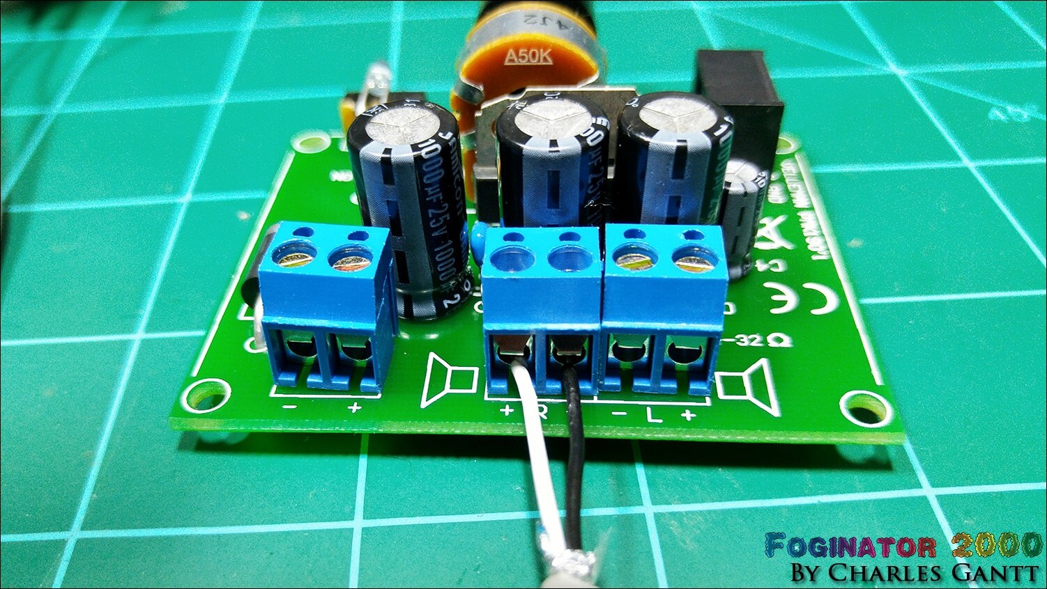
Connect the other end of the speaker wire to the amp while paying attention to the polarity. You can also connect the power cable to the screw terminals to the left at this point. The amp requires a 6-14v 1A DC power source. You can power this with an old 9v or 12v wall-adapter, or even a 9-volt battery, but the battery will struggle to output enough current to keep the amp at full capacty.
The Ambient Audio Code
To start off let's quickly cover the background / ambient audio working and how I set it up to begin when the Raspberry Pi Boots. Below is the Python script that I wrote to play the mp3 file I selected as the ambient source. I have broken out each section, and commented on what it does. You can download this code used in this tutorial at the Github repository for this project. The audio files are available for download from here. If you do not want to modify the code, create a folder in the Desktop directory called “audio” and move all three of the mp3 files into it.
To get started we need to import the pygame library. I know a lot of you would have liked to see me use OMXplayer, but there were some things I could not get to work as they should, and I just chose to use something I was familiar with instead.
import pygame
Next we need to define the path to the ambient.mp3 file, and give it a name.
audio_path = '/home/pi/Desktop/audio/ambient.mp3'
Now we need to set a variable to True
var = True
Now we need to write a while-loop to play our mp3 file, and set it to only play if var is equal to True.
while var ==True:
Now we need to initialize PyGame.
pygame.mixer.init()
Then we need to load the MP3 file we want to play.
pygame.mixer.music.load(audio_path)
Now we need to set the pygame player’s volume. The range is between 0.0 and 1.0 so a setting of 0.5 would be half way.
pygame.mixer.music.set_volume(1.0)
Finally we need to tell pygame to play the MP3 file, and set it to loop five times.
pygame.mixer.music.play(5)
The full code is pasted below. Alternatively you can download this code used in this tutorial at the Github repository for this project. The audio files are available for download from here. If you do not want to modify the code, create a folder in the Desktop directory called “audio” and move all three of the mp3 files into it.
import pygame

audio_path = '/home/pi/Desktop/audio/ambient.mp3'

var = True

while var ==True:
    pygame.mixer.init()
    pygame.mixer.music.load(audio_path)
    pygame.mixer.music.set_volume(1.0)
    pygame.mixer.music.play(5)
Navigate to the project files folder adn then open a new file called ambient.py using the Nano text editor by entering the following command
sudo nano ambient.py
Then copy and paste the code above into the file. Save and exit, and then use the following command to test the pi.
sudo python ambient.py
You should hear the ambient.mp3 file begin to play if you have the amplifier / speaker combo we just built hooked up via a 3.5mm to 3.5mm audio cable from the amp to the Raspberry Pi. To get this python script to run on boot, we need to add it to the Raspberry Pi’s crontab. Enter the following command in the terminal to create a new crontab entry.
sudo crontab -e
Now paste the following line at the bottom of the crontab.
@reboot sudo python /home/pi/Desktop/Foginator2000/ambient.py
then save and exit out of the file. Reboot the Raspberry Pi using the command below. When the Pi reboots, you should hear the ambient.py file playing after you login.
sudo reboot
If the audio is quite low despite the amplifier’s volume being maxed out, you will need to turn the Raspberry Pi’s volume up. This is as simple as entering the small command found below, into the terminal.
amixer cset numid=1 -- 400
The range of amixer’s volume is -10200 and +400 in centi-dB units. Since we are using an external amplifier, we can set the Raspberry Pi’s volume to its max setting at +400, and adjust the volume on the amp accordingly. Once you have the volume set, you should be able to reboot the Pi, and the ambient audio will begin playing when you log in. I did not shoot a video of this for this installment, but if you check out the video below from my Trick or Trivia project, you will get the idea of whats going on with the ambient audio.
Well that is going to wrap up this weeks installment of the Foginator2000 project. Check back in a few days for the next update where I cover how to get Individually Addressable RGB LEDsIndividually Addressable RGB LEDs working with the Raspberry Pi, and how they will be incorporated into this project! If you have not checked it out yet, head over to my other Halloween 2015 Raspberry Pi project, Trick or Trivia, that makes use of the new 7-inch Touchscreen LCD from Raspberry Pi.7-inch Touchscreen LCD from Raspberry Pi.
- Project Introduction
- Fog Controller Hardware and Test
- Environment Sensing Coding & Testing
- Ambient Audio Hardware and Coding
- Lighting Coding and Testing
- October 16th - Final Assembly and Testing
- October 23th - Project Wrap-up
Originally published by Charles Gantt on Element14 Community
Part 5: Foginator 2000: #005: Neopixel Integration with Raspberry Pi and Arduino

Welcome to installment #005 of Project: Foginator 2000, part of the 2015 Raspberry Pi Halloween Project series here at Element14. In this week's episode I am going to demonstrate how to get Neopixel (WS2812B) LED modules working with the Raspberry Pi 2. Unfortunately as you will see, this is an almost impossible task as the previously working library is only compatible with Raspberry Pi versions up to the Model B+.
Below is a table containing the parts you will need for this segment of the project. In addition to these parts you will need to connect the Raspberry Pi to the internet either via a wifi dongle, or a wired Ethernet connection. You will also need three colors of stranded hook-up wire, a soldering station, solder, and some 0.100 male header pins.
Newark Part No. | Notes | Qty | Manufacturer / Description |
38Y646738Y6467 | RPi | 1 | RASPBERRY PI 2, MODEL B |
38Y647038Y6470 | SD Card | 1 | RASPBERRY PI 8GB NOOBS MICRO SD CARD |
44W493244W4932 | PSU | 1 | USB PORT POWER SUPPLY 5V, 1A |
06W104906W1049 | USB Cable | 1 | USB A PLUG TO MICRO USB B PLUG |
53W628553W6285 | WiFi Dongle | 1 | USB WIFI MODULE |
26Y845826Y8458 | Fog Coloring Rings | 1 | NEOPIXEL RING - 16 X WS2812 |
26Y846026Y8460 | Mood LEDs | 1 | NEOPIXEL DIGITAL RGB 1M 144LED BLACK |
34C109234C1092 | PSU Vreg | 1 | LM7805 LINEAR VOLTAGE REGULATOR, 5V, TO-220-3 |
58K379658K3796 | PSU LED Resistor | 1 | METAL FILM RESISTOR, 1KOHM, 250mW, 1% |
17F216517F2165 | PSU Filter Cap | 1 | CERAMIC CAPACITOR 0.1UF, 50V, X7R, 20% |
69K794969K7949 | PSU Filter Cap | 1 | ELECTROLYTIC CAPACITOR 47UF, 50V, 20% |
69K790769K7907 | PSU Filter Cap | 1 | ELECTROLYTIC CAPACITOR 100UF, 50V, 20% |
14N941814N9418 | PSU LED | 1 | LED, RED, T-1 3/4 (5MM), 2.8MCD, 650NM |
| 49Y756949Y7569 | RPi Sense Hat | 1 | Raspberry Pi Sense HAT |
| 13T927513T9275 | Arduino Nano | 1 | Arduino Nano V3 |
| 38K032838K0328 | 10k Resistor | 1 | Multicomp 10k Resistor |
The Theory

Neopixel’s are the brand name for the popular WS2812B individually addressable RGB LED modules, and are marketed and sold by Adafruit here at Element14. You can find WS2812B strips, rings, sticks, and individual modules on various electronic retail outlets as well, but for the purpose of this project, I will be using genuine Neopixel strips and rings from Adafruit.
The NeoPixel line is the latest advance in the quest for a simple, scalable and affordable full-color LED. Red, green and blue LEDs are integrated alongside a driver chip into a tiny surface-mount package controlled through a single wire. They can be used individually, chained into longer strings or assembled into still more interesting form-factors.
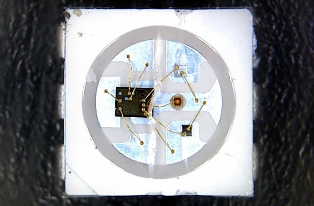
As you can see, each Neopixel contains a small microcontroller built into each LED module, with control wires emanating to each LED die. Neopixels use a single-wire protocol making them easy to integrate into any project without consuming valuable GPIO resources. Neopixels pass data along to the next module in-line, and can be individually controlled in single module,strip and matrix form factors.
Unfortunately, Neopixels require very strict timings, and this causes a lot of headache when attempting to control them from something like a Raspberry Pi, as it’s GPIO pins are software based, and not hardware based like those of an Arduino. Raspberry Pi models up to the B+ were able to skirt around this limitation thanks to the excellent rpi_ws281x library created by Jeremy Garff, but as I recently found out, the library does not seem to function on the new Raspberry Pi 2 boards.
I spent a good portion of last week looking for a solution to this problem, and to be honest, I came up with nothing. This caused me to freak out a little bit, and Neopixels play a very large role in this project. After much deliberation, and consultation with some friends here at Element14, I decided to abandon my quest to get Neopixels working with the Raspberry Pi 2. Instead of directly controlling them with the Pi, I decided to go a much easier route, by controlling them with an Arduino Nano, which will be triggered by the Raspberry Pi.
As many of you may already know, Adafruit has an excellent guide to getting Neopixels up and running on an Arduino, and even wrote their own library. (Albeit it is a modified version of the pre-existing fastLED library.) To keep things simple and easy to understand for those of you following along at home, I stuck with the Adafruit Neopixel Library despite being more familiar with the fastLED library. If you are looking for more code examples for driving WS2812B modules, give fastLED a try.

As I briefly mentioned earlier, Neopixels utilize a single-wire data format, meaning they only require a single data wire regardless if your strip has one module or one thousand modules. The only other connections required are 5V and GND connections. It is very important to remember that with each “pixel” you get three LEDs that are being driven. This means that Neopixel strips, and rings can draw a large amount of current. I find that on a standard Arduino board, only about 60 Neopixels can be driven before browning out the board, and that number diminishes by half, if the strip is set to display white at full brightness.
For this reason, I recommend driving your Neopixels with a separate power source such as a 5V 1A regulated source, or a 5V 2A wall transformer. You can also power the strip with a 4x AA battery box. Adafruit also recommends filtering the power input with a large capacitor, and limiting the current on the data line with a resistor. I find that this is usually not needed, but it will prevent a pixel from dying in the event you accidentally plug the strip in while the system is powered up.
Wiring the Neopixels, Arduino Nano, and Raspberry Pi
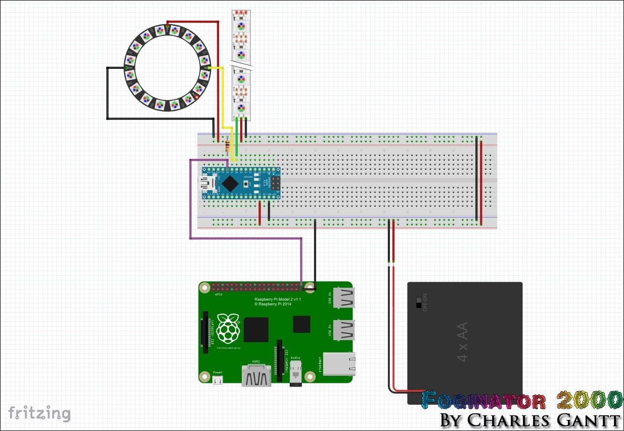
Wiring up the Neopixels to the Arduino is fairly straightforward,and is as simple as following the diagram above. Note that I have connected the data-in line from both the Neopixel Ring and the Neopixel strip to the Arduino Nano’s digital pin 6. This allows me to drive both Neopixel devices with the same code. Also note that I have connected a 4X AA battery pack in the image for illustration purposes. As you will see later, I am using an LM805 VReg-based power supply in the physical application.
Connecting the Raspberry Pi to the Arduino is simple as well. Connect the Raspberry Pi’s GPIO Pin 21 to the Arduino Nano’s Digital Pin 8. Then connect one of the Raspberry Pi’s GND pins to the shared GND circuit between the Neopixels and Arduino Nano. It is very important that all of the ground’s in this circuit are connected together. Finally, a 10k Ohm resistor needs to be connected as a pulldown resistor on the Arduino’s Digital Pin 8. This will prevent any false triggers from happening.
Since we are using the Raspberry Pi Sense Hat with our Raspberry Pi, we need to make some slight modifications to the Sense Hat before we can connect any jumper wires to the GPIO headers. As you can see in the image above, the header pins that come with the sense hat do not protrude past the black plastic bar on top of the sense hat.
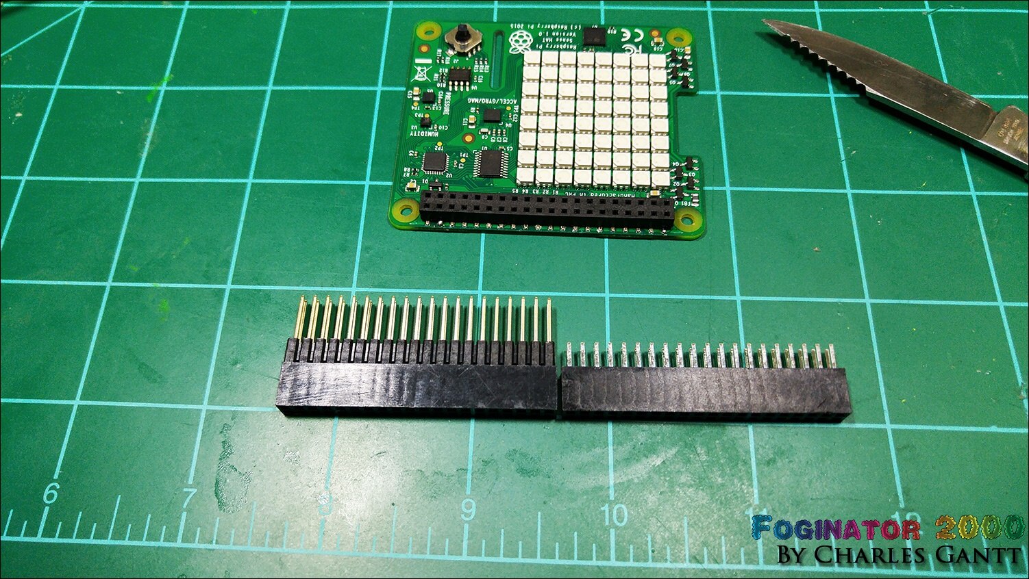
Unfortunately figuring out how to get around this issue is not something that has been widely discussed anywhere on the internet. However, I did manage to find a post on the Astro Pi forums that mentioned buying some extra-long header pins from Adafruit. This is one of the reasons this post has been delayed for so long. As you can see in the image above, the extra-long pins from Adafruit are about 5mm longer than the ones that ship with the Sense Hat.
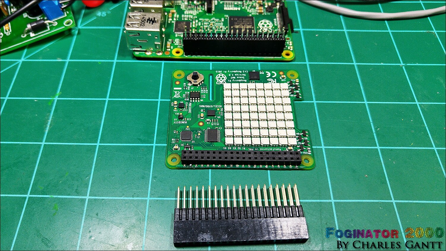
The first step in installing the new header pins is to gently pry the Sense Hat off of its existing header pins. The Sense Hat was designed with this in mind, and prying the existing header pin strip out is easy when done slowly and carefully with a small flat-blade screw driver. Once removed, you can simply slide the longer header pins into place.
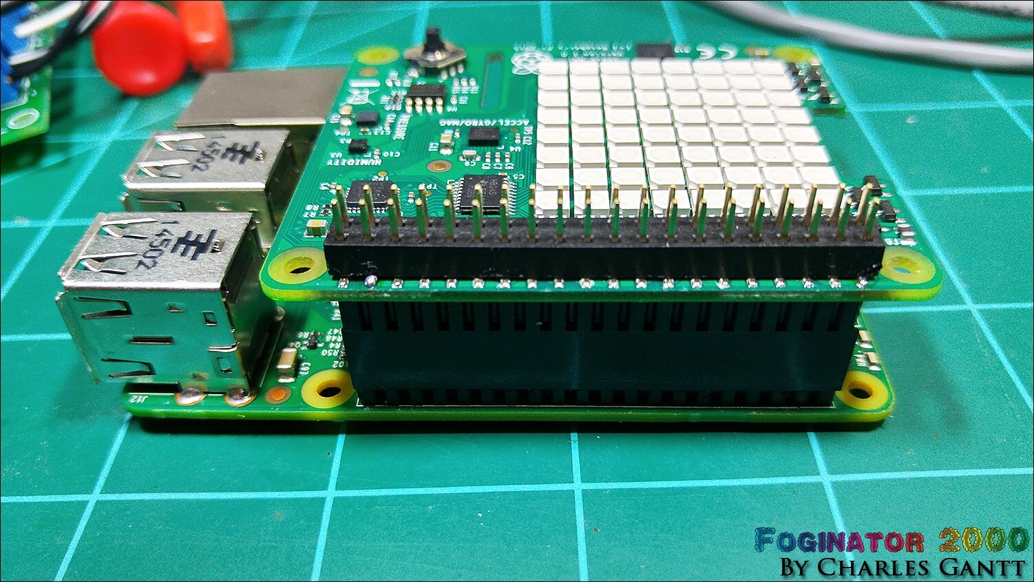
Now you are ready to hook up everything as per the instructions above. In the image below you can see how I have everything laid out. Note that for this portion of the project to work, you need to have followed all of the previous installment’s instructions as well.
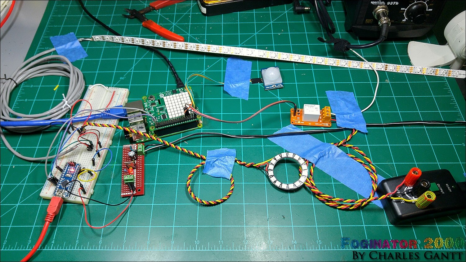
It looks like a bit of a mess, but with everything laid out and taped down, I could easily troubleshoot any issues that arose.
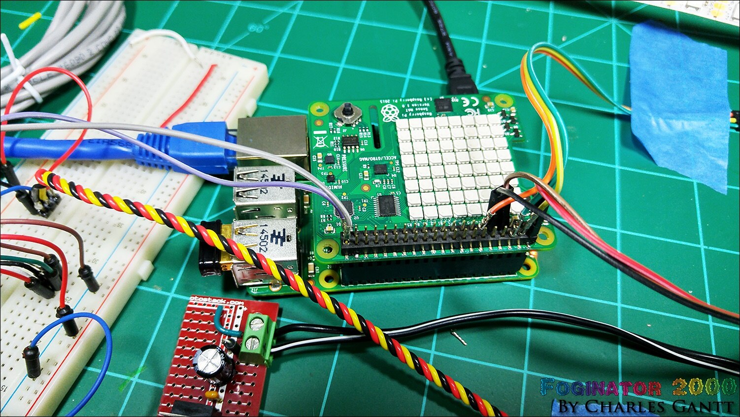
Here you can see the connections made to the Raspberry Pi. Note that I have removed some of the plastic connectors from some of the jumper wires. The header pins only stick about 5mm above the surface of the black plastic bar, and some of my jumpers were having issues keeping a secure connection.
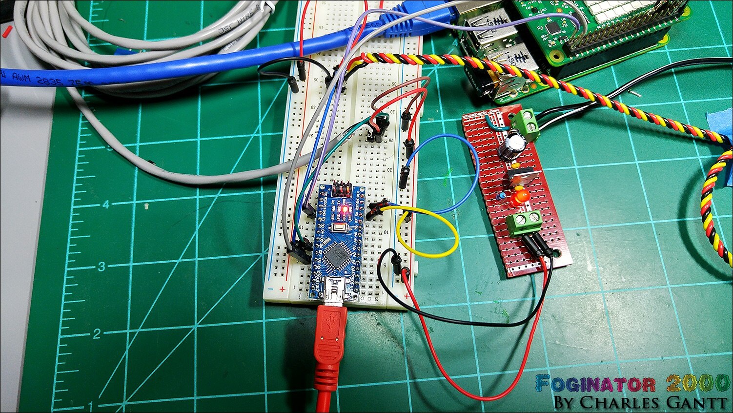
Here is a shot of how I have the Arduino Nano connected to the breadboard and wired up. Note that the grey wire is connected to the neopixel strip, and the twisted yellow, red, and black wires are connected to the neopixel ring. In this image, you can also see the LM7805-based 5V power supply I built. More on that later.
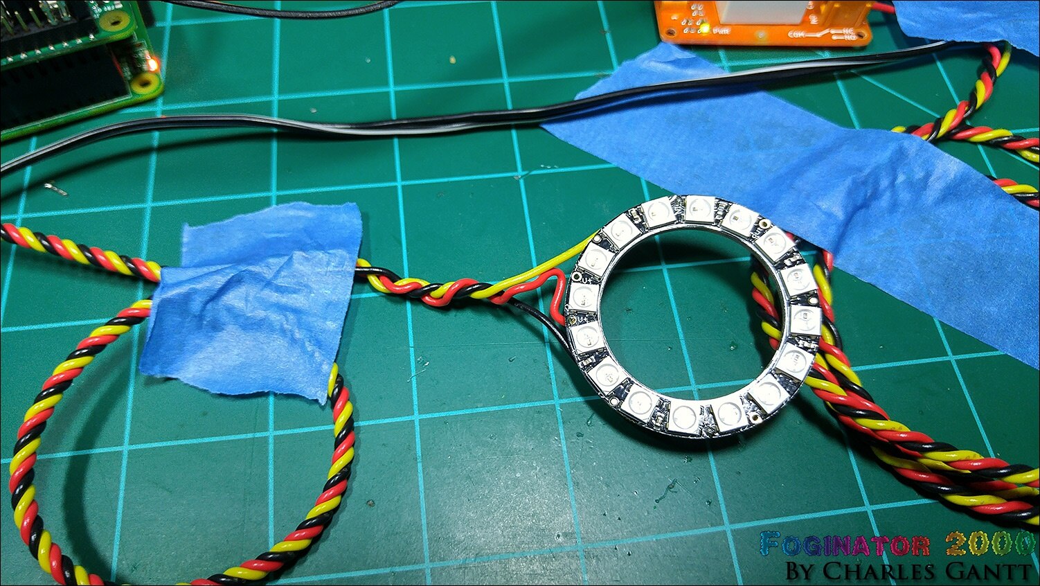
Finally, a shot of the NeoPixel ring wired up. Note that these rings do not come pre-wired, and you will need to solder wires to it.
Building a 5V Regulated Power Supply
This is the same PSU that I built for my Trick or Trivia Halloween Candy Dispenser #004 - Building The Candy Dispenser & Servo Coding project, so I have re-used its images below. To build this PSU you will need the following components, as well as a soldering iron, flush cutters, and a 12-30V DC power source.
58K382758K3827 | Resistors | 1 | METAL FILM RESISTOR, 220 OHM, 250mW, 1% |
10M846410M8464 | General Purpose Diode | 1 | 1N40011N4001 Rectifier Diode 50 V 1 A |
34C109234C1092 | PSU Vreg | 1 | 7805 LINEAR VOLTAGE REGULATOR, 5V, TO-220-3 |
17F216517F2165 | PSU Filter Cap | 1 | CERAMIC CAPACITOR 0.1UF, 50V, X7R, 20% |
69K790769K7907 | PSU Filter Cap | 1 | ELECTROLYTIC CAPACITOR 100UF, 50V, 20%, |
14N941814N9418 | PSU LED | 1 | RED, T-1 3/4 (5MM) |
| 49Y171249Y1712 | 7-Inch Touch Screen | 1 | Raspberry Pi 7" Touch Screen Display |
| 66H746266H7462 | Strip Board | 1 | VECTOR ELECTRONICS-8022-PCB, Tracks(Strip Board) |
| 21M490921M4909 | Screw Terminal | 2 | MOLEX-39543-0002-TERMINAL BLOCK |
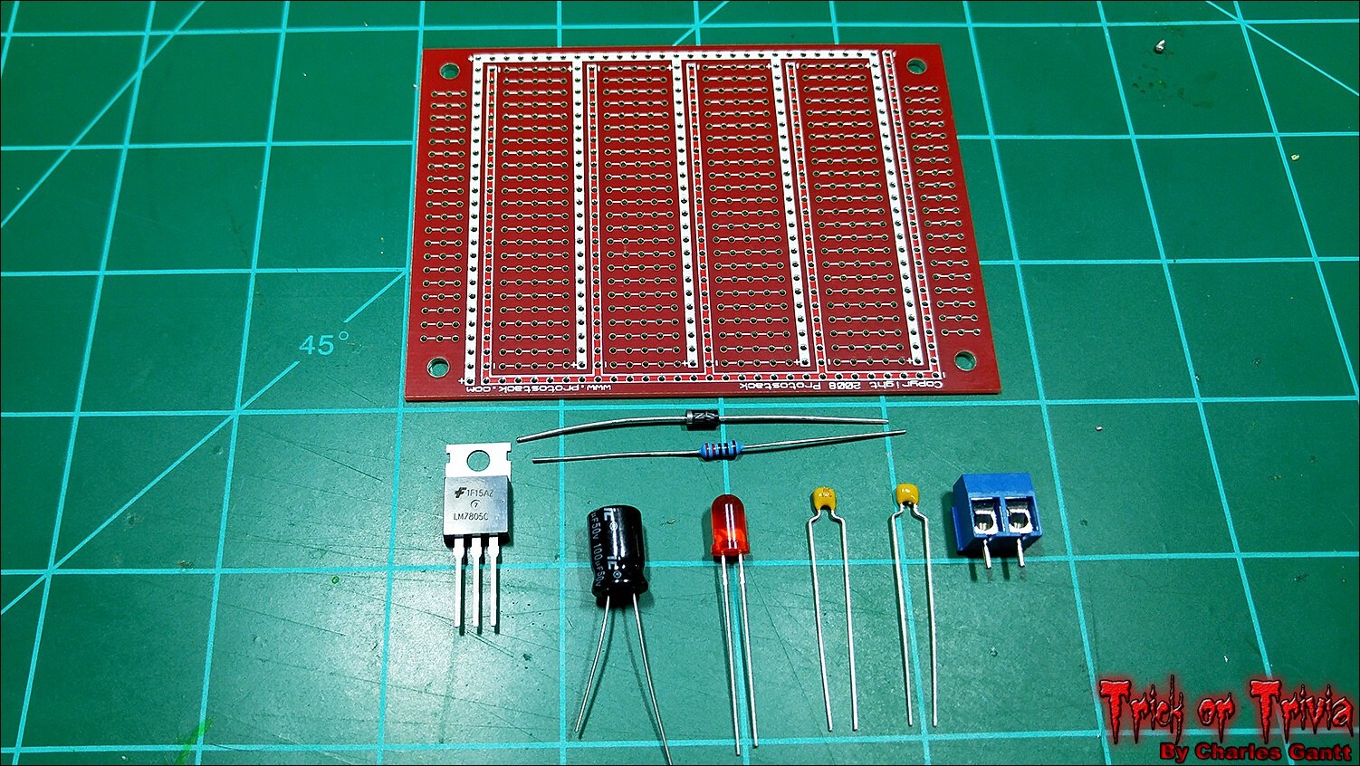
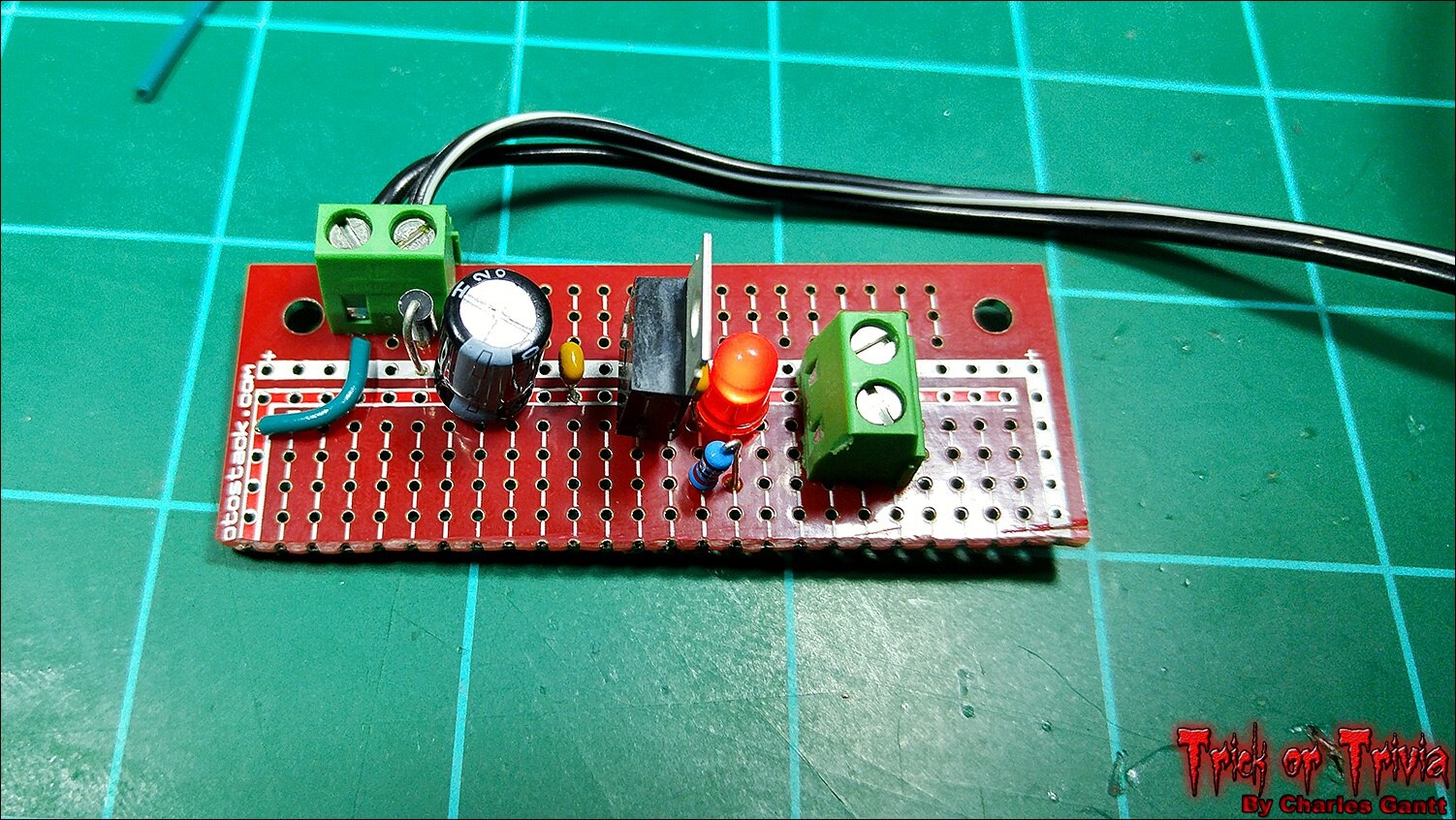
A 5V regulated power supply circuit is quite simple to build thanks to the fairly common LM7805 voltage regulator, and requires just five components to get up and running. A 100uF capacitor, two 0.1pF ceramic capacitors, a 1N004 diode, and the LM7805 regulator. I am adding two screw terminals, and an indicator LED to the mix. I want to design a pcb for this, but for now a piece of protoboard will work just fine.
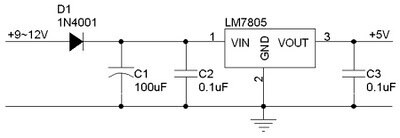
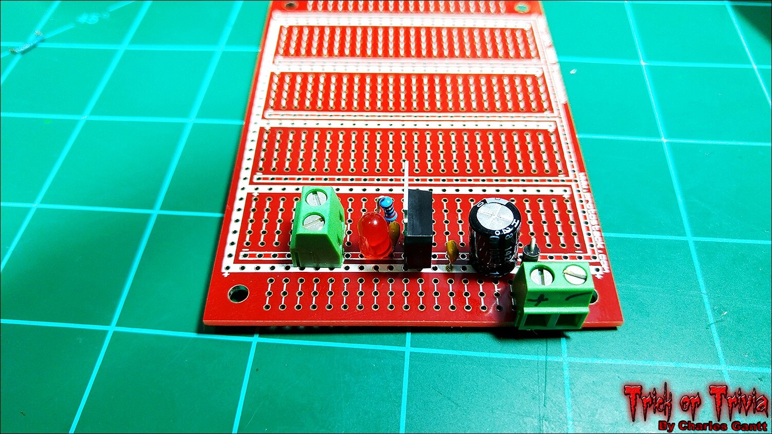
Following the schematic above, build the power supply and solder in each component. The protoboard I am using is different from the one listed above as I have a big supply of these from Protostack.com, so I just used one of mine.
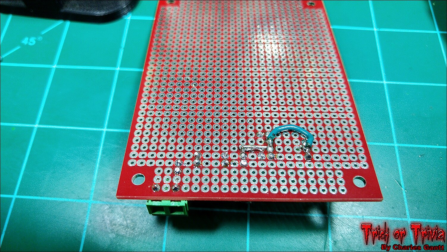
With all of the components soldered together, I made the necessary jumps from each component to the next. I lucked out with the Protostack board as it has integrated power and ground rails. This cut down on the number of jumps I needed to make.
With everything soldered up, I trimmed the board down to reduce its size, and connected a 12v 1amp power source. The red LED lit up and I confirmed 5V out with a multimeter.
The Neopixel Code
With everything connected, load the Arduino IDE and make sure the Adafruit Neopixel Library is installed. Refer to Adafruit’s Neopixel Uber Guide if you need help installing the library. Additionally, I won’t be going over the Arduino sketch that will drive the Neopixels in great detail as Adafruit does a good job at that in the code’s comments.
To keep things simple, I am using a modified version of Adafruits Strand Test example. I have added some custom code that looks for a high signal on the Arduino Nano’s digital pin 8, and included an else statement that tells the neopixels to turn off if no high signal is present. As always, you can find all of the code used in the Foginator 2000 project at its Github Repository.
/* This code is adapted from the StrandTest example from Adafruit's Neopixel library. Please visit adafruit.com to download the neopixel library in order to use this code. https://learn.adafruit.com/adafruit-neopixel-uberguide/arduino-library */

#include <Adafruit_NeoPixel.h>

#define PIN 6

// Parameter 1 = number of pixels in strip
// Parameter 2 = Arduino pin number (most are valid)
// Parameter 3 = pixel type flags, add together as needed:
//  NEO_KHZ800  800 KHz bitstream (most NeoPixel products w/WS2812 LEDs)
//  NEO_KHZ400  400 KHz (classic 'v1' (not v2) FLORA pixels, WS2811 drivers)
//  NEO_GRB    Pixels are wired for GRB bitstream (most NeoPixel products)
//  NEO_RGB    Pixels are wired for RGB bitstream (v1 FLORA pixels, not v2)
Adafruit_NeoPixel strip = Adafruit_NeoPixel(60, PIN, NEO_GRB + NEO_KHZ800);

// IMPORTANT: To reduce NeoPixel burnout risk, add 1000 uF capacitor across
// pixel power leads, add 300 - 500 Ohm resistor on first pixel's data input
// and minimize distance between Arduino and first pixel.  Avoid connecting
// on a live circuit...if you must, connect GND first.

int rasPin = 8; // defines digital pin 8 as rasPin
int val = 0; // creates an integer called val, and assigns it a value of 0.

void setup() {
  strip.begin(); // Initialize the pixel strip
  strip.show(); // Initialize all pixels to 'off'
  pinMode(rasPin, INPUT); // sets rasPin to an Input pin
  }

void loop() {
val = digitalRead(rasPin); // tells the arduino to take a reading on rasPin and store the value in the val integer we declared earlier.

if (val == HIGH) // says if val is equal to 1, run the following code
{
  delay(1000); // wait one second
  rainbowCycle(30); // run the rainbowCycle function
  }
  else // tells the arduino that if val equals anything other than 1 (high) to run the following code.
  {
  colorWipe(strip.Color(0,0,0), 100); // sets each pixel to black (off) one by one via the colorWipe function
    }
}

// This function makes a rainbow equally distributed throughout the strip
void rainbowCycle(uint8_t wait) {
  uint16_t i, j;

  for(j=0; j<256*5; j++) { // 5 cycles of all colors on wheel
    for(i=0; i< strip.numPixels(); i++) {
      strip.setPixelColor(i, Wheel(((i * 256 / strip.numPixels()) + j) & 255));
    }
    strip.show();
    delay(wait);
  }
}

// This function fill the dots one after the other with a color
void colorWipe(uint32_t c, uint8_t wait) {
  for(uint16_t i=0; i<strip.numPixels(); i++) {
      strip.setPixelColor(i, c);
      strip.show();
      delay(wait);
  }
}

//This code generates a color-wheel value generator.
// Input a value 0 to 255 to get a color value.
// The colours are a transition r - g - b - back to r.
uint32_t Wheel(byte WheelPos) {
  if(WheelPos < 85) {
  return strip.Color(WheelPos * 3, 255 - WheelPos * 3, 0);
  } else if(WheelPos < 170) {
  WheelPos -= 85;
  return strip.Color(255 - WheelPos * 3, 0, WheelPos * 3);
  } else {
  WheelPos -= 170;
  return strip.Color(0, WheelPos * 3, 255 - WheelPos * 3);
  }
}
Now upload the above code to the Arduino. If you have an error, check that the Neopixel library is properly installed, and that your Arduino is connected to the correct com-port.
Python Code To Trigger Arduino Via Raspberry Pi
Making an Arduino do something based on a trigger from a Raspberry Pi is quite simple, and only requires a few lines of code. Since we are looking for a high-input on the Arduino, we simply need to tell the Raspberry Pi to set one of its GPIO pins as an output when we want the Arduino to do something. In our case, we want the Neopixels to light up when the motion sensor is tripped. This will allow us to illuminate the fog that was triggered by the motion sensor as well.
Below you will find the code. I have not broken it down as it is simply just a few lines that set GPIO Pin 27 to an output when the motion sensor is tripped.
import RPi.GPIO as GPIO
import time
import sys

GPIO.setwarnings(False)
GPIO.setmode(GPIO.BCM)
GPIO.setup(4, GPIO.OUT)
GPIO.setup(17, GPIO.IN)
GPIO.setup(21, GPIO.OUT)

def fire_fog():
    GPIO.output(21,True)
    time.sleep(2)
    GPIO.output(4,True)
    time.sleep(10)
    GPIO.output(4,False)
    time.sleep(20)
    GPIO.output(21,False)
    GPIO.cleanup()
    sys.exit()

while 1:
    time.sleep(3)
    if GPIO.input(17)==True:
        fire_fog()
Testing The Code
Power the Raspberry Pi, Arduino, and Neopixel power supply up, and then connect to the Raspberry Pi via SSH with a terminal like Putty, or Terminal if you are using a Mac. Using the Nano text editor, create a new file called foginator_ledfx_demo.py using the command below.
nano foginator_ledfx_demo.py
Now paste the Python code from the previous section above, and then save and exit the Nano text editor. If everything is hooked up correctly, and the code has been copied and pasted correctly, you can run the command below to see the neopixels light up.
sudo python foginator_ledfx_demo.py
You will have to wait for a few seconds, then move your hand over the motion sensor. The program will wait about two seconds, and then trigger the relay which fires the fog. At the same time, the Raspberry Pi will send a high signal to the Arduino which will trigger the NeoPixel strip and ring. Check out the video below to see it in action.
So that wraps up part five of the Foginator2000 project. This was a really fun but frustrating portion of the project for me as I lost a lot of time trying to sort out the Neopixel / Raspberry Pi 2 incompatibility issues. In the end, everything worked out well, but I was forced to add another part to the project’s bill of materials. Recently, a newly acquired friend of mine, who just happens to be a EE, told me that being an engineer means that you spend more than half your time problem solving. After this portion of the project, I am highly inclined to believe him.Tune in in just a few days for my next installment on the Foginator2000 project. Until then remember to Hack The World and Make Awesome!
- Project Introduction
- Fog Controller Hardware and Test
- Environment Sensing Coding & Testing
- Ambient Audio Hardware and Coding
- Lighting Coding and Testing
- October 16th - Final Assembly and Testing
- October 23th - Project Wrap-up
Originally published by Charles Gantt on Element14 Community
Part 6: Foginator 2000: #006 Final Assembly and Testing

Welcome back to Project: Foginator 20000! In this installment we are going begin wrapping the build up by moving everything from the breadboard, to a prototyping PCB, and then placing it all into an enclosure. Then we will wrap everything up with a demonstration of the final code. There will be one more installment after this one, which will include actual data from Halloween night. I will also finalize the bill of materials in the final post as well.
The Parts
The only special parts we are using tonight is a piece of prototyping board, and a project enclosure. You will need something to cut holes into the project box. I used a dremel multitool with a cutoff wheel, drill bits, and some hand files to accomplish this. You will also need a hot glue gun, to secure the PCBs and the motion sensor.
MCM Part No. | Notes | Qty | Manufacturer / Description |
Prototyping Board | 1 | Circuit Board - 750 Holes | |
Project Enclosure | 1 | ABS Case Gray - 5-5/8" x 3-1/8" x 1-3/16"
|
The Build
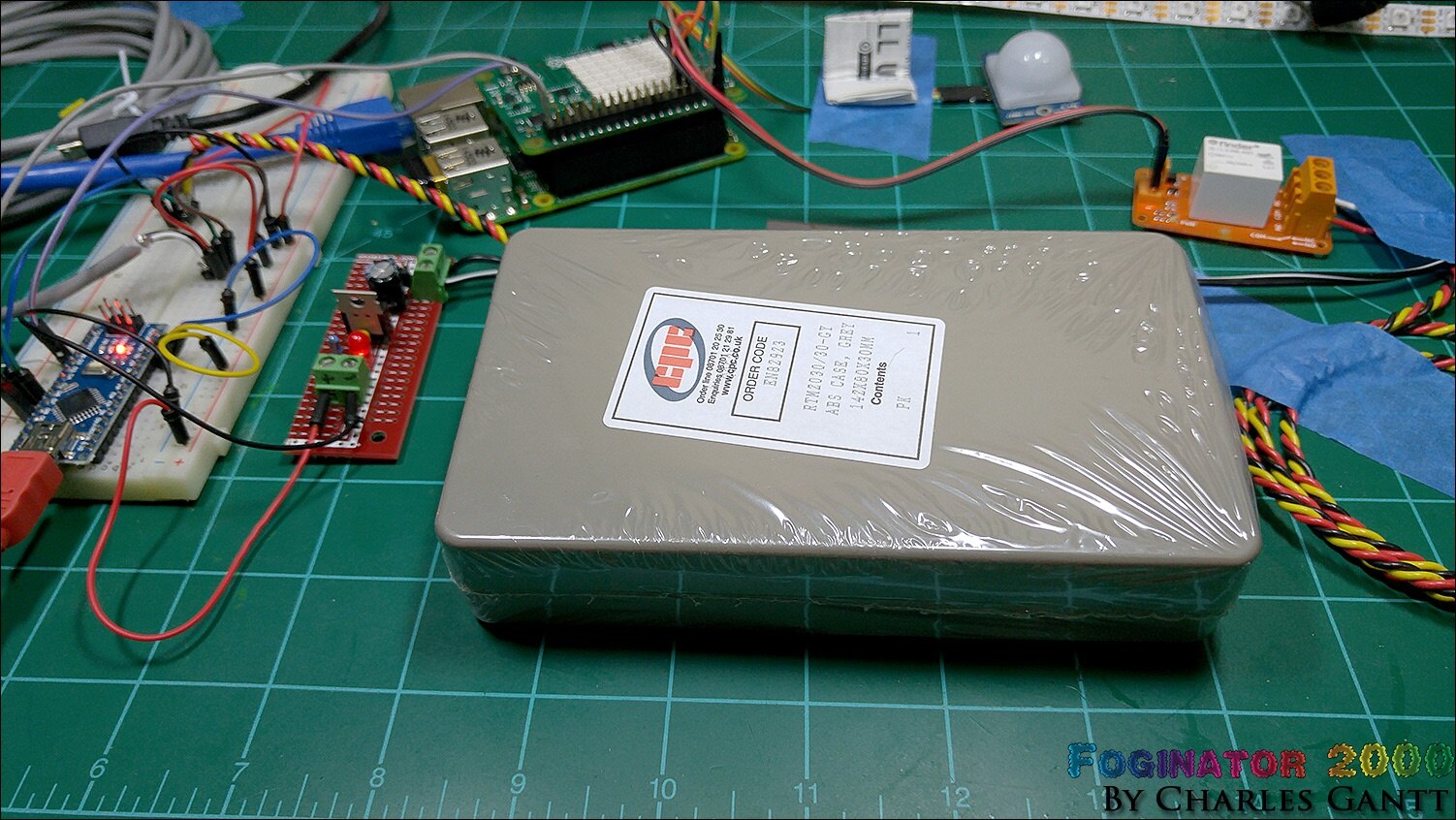
To get started let’s look at how the project box is laid out internally. Idealy, a 5” thick box would be used so that the Raspberry PI and Sense Hat could be placed in the enclosure as well. Unfortunately I was unable to find one large enough at Newark or MCM Electronics. So we are going to use this enclosure that is just large enough to house the rest of the electronics.
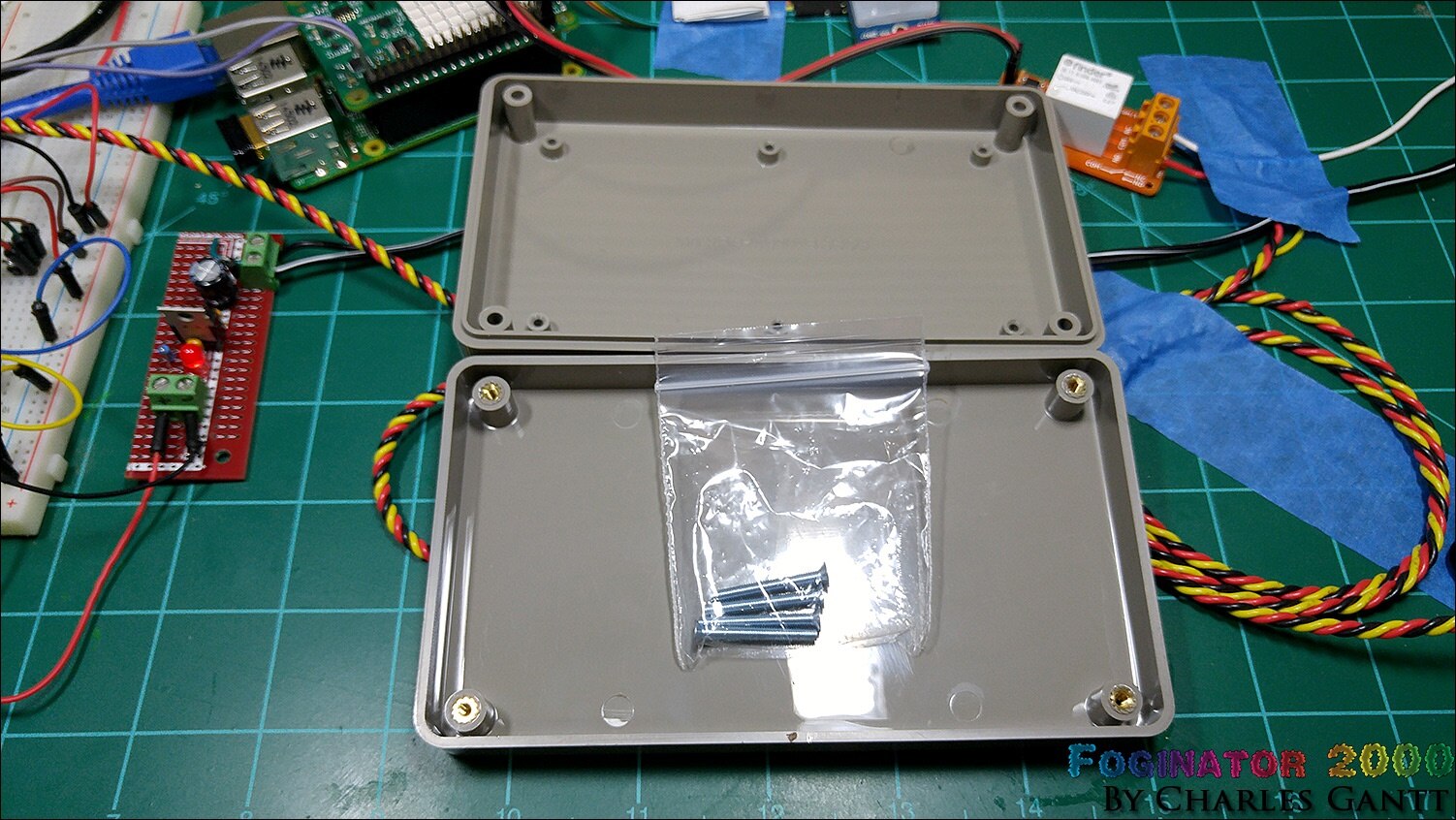
The inside of the project enclosure has several standoffs on one side, and just the enclosures screw standoffs on the other. I am going to use the clean side as the bottom of the box since none of my boards will align with the mounting standoffs on the other side.
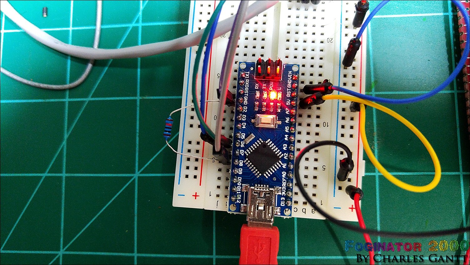
This is the main portion of what we need to move to a prototyping PCB. The Arduino Nano, a pulldown resistor, and the LED cable connections.
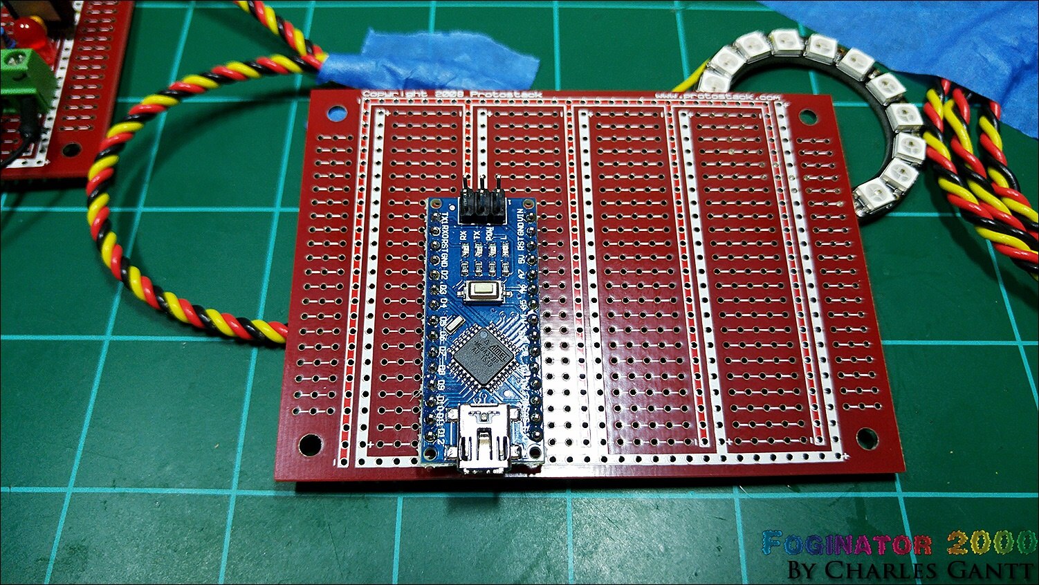
I am again using a Protostack protoboard as I have several laying around. You can use any prototyping board you would like though. I chose to only solder the pins that I was using as well as the 5V and GND pins.
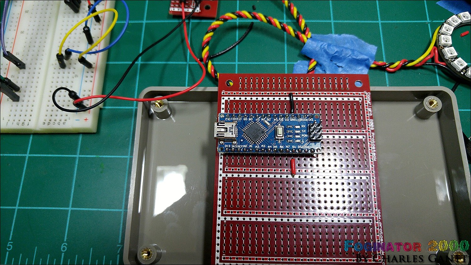
Here you can see that I used jumper wires to connect the GND and 5V lines on the Arduino Nano to the GND and VCC rails on the prototyping board. That is why I love these little boards from Prototstack. They are laid out like a breadboard, with five of the holes connected, and the power rails encircling everything.
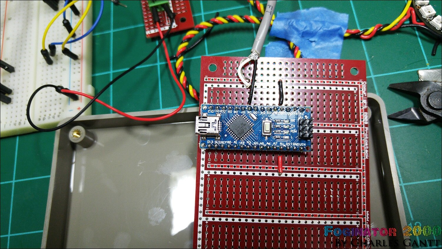
With the power connections made, I soldered in the Neopixel strip. I am not a fan of the microphone cable I used for the connection when soldering to these boards. Their holes are designed for smaller through hole pins, but with a little finesse it fits well. You will notice that I did not solder in the Neopixel ring. I think I killed it on accident, as I could not get it to light up at all.
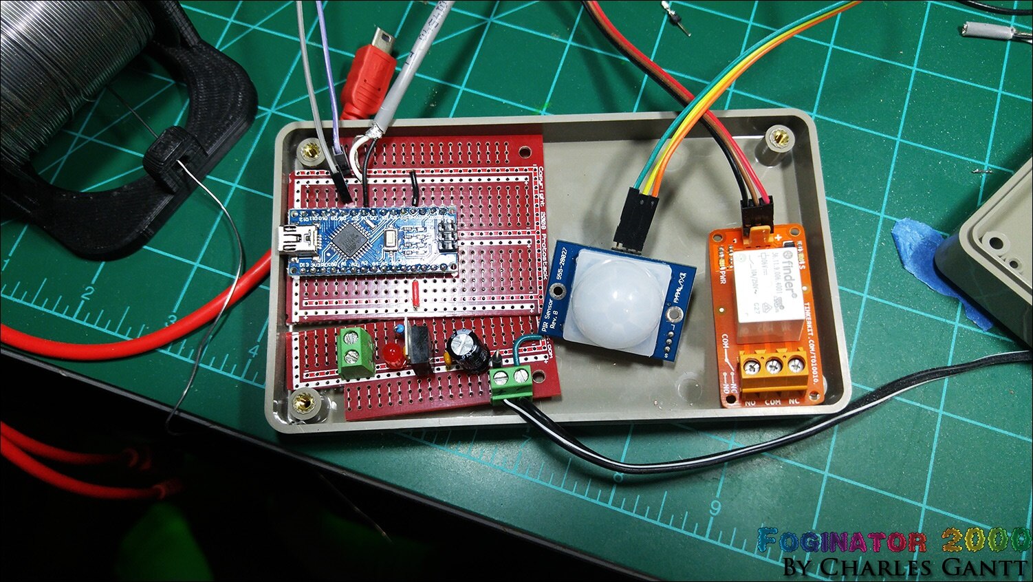
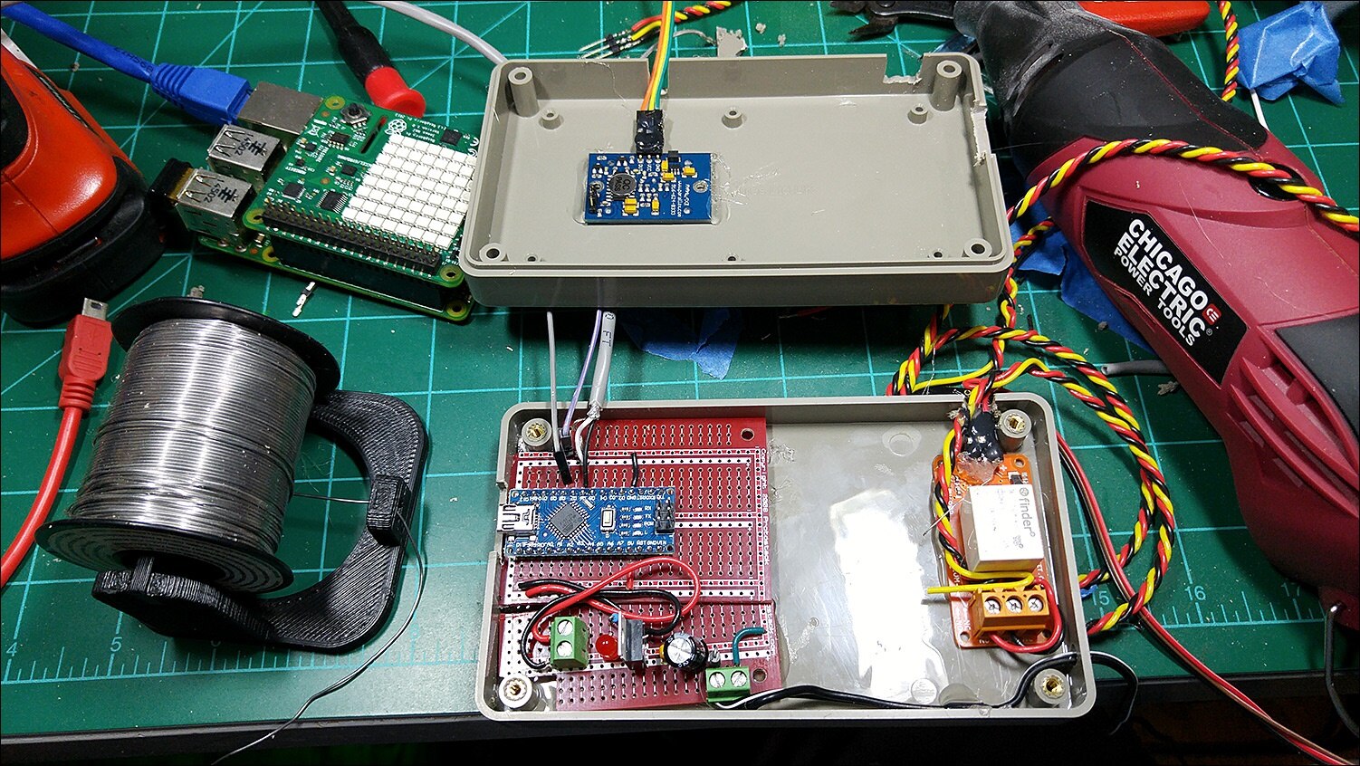
Here you can see the basic layout . Notice I notched both the Arduino protoboard and the 5V power supply board. I forgot to take pics of this process, but I used a hacksaw blade to cut them. A dremel would work too but it produces a lot of glass fiber dust that is very bad to breath. The relay sits on the right, and the PIR sensor will be placed in the top cover through a hole.
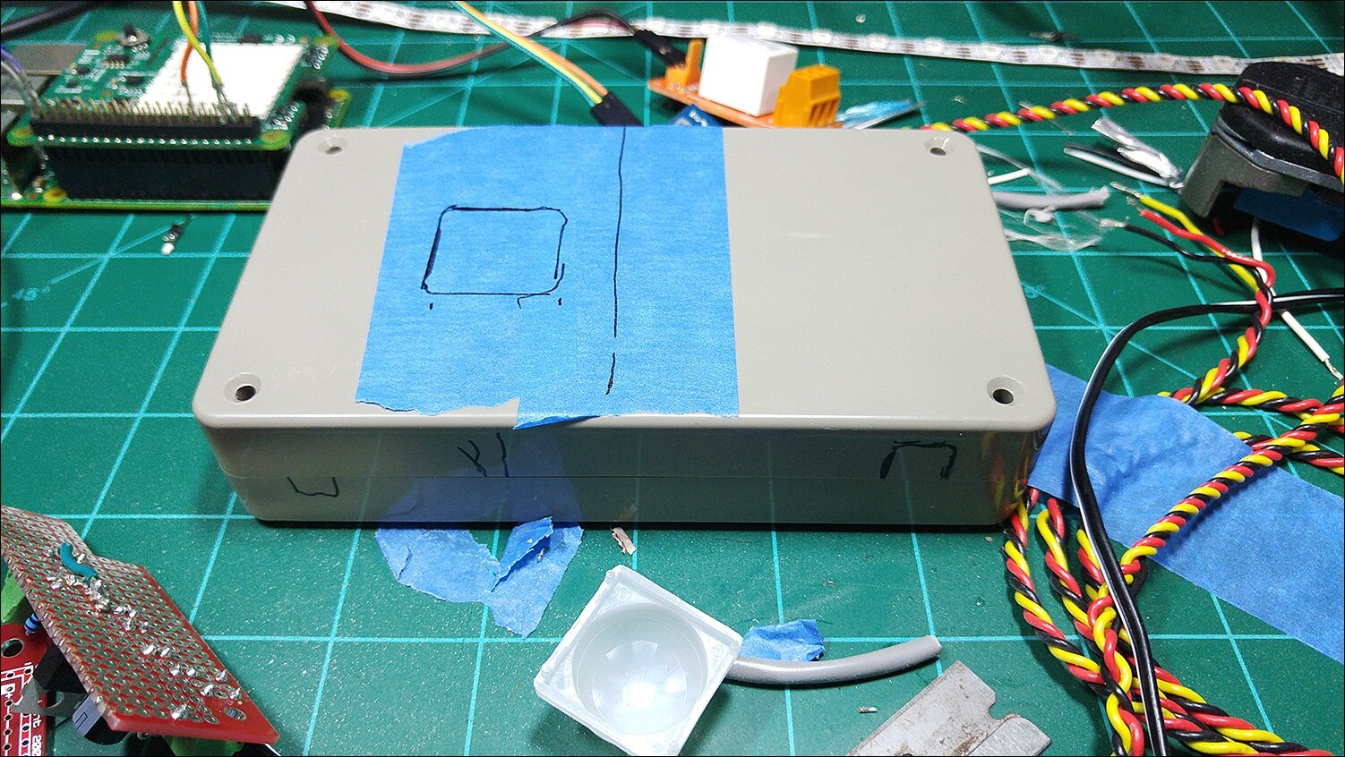
This enclosure needs several holes for the wiring to exit. Here you can see some of them laid out. I used a dremel tool, a drill and drill bit, and some hand files to create and clean up these holes.
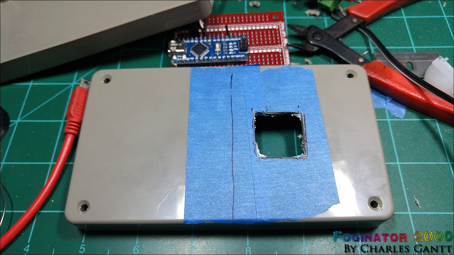
Here’s the hole roughed out for the PIR sensor. It is important to get the sensor mounting flush with the top of the case for space concerns inside.
Once everything is fitting nice and tight, I used hot glue to secure the PIR sensor to the case. Note that I hot glued the jumper wires to the pins as well. This prevents them from pulling loose later.
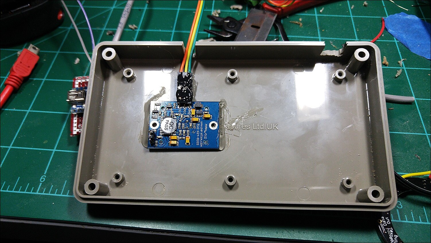
Here you can see everything glued into place, and the power wire ran to the power supply. Not pictured is the dobs of glue that I used to hold all the wires that exit the case in place.
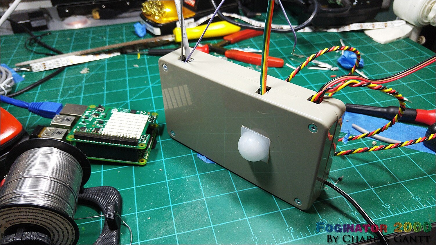
While it is not the most discrete motion sensing project enclosure ever made, it sure does look good once everything is closed up nice and tight.
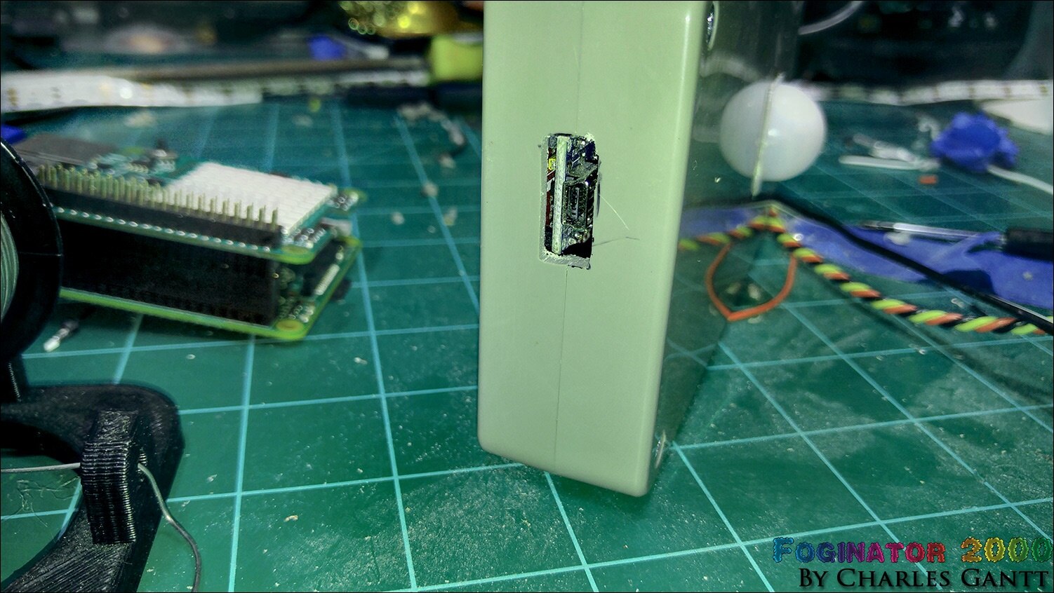
Thinking ahead in case I ever wanted to reprogram the Arduino, I cut a slot that would allow me to plug in a USB cable. I made the slot oversize as the USB cables I like to keep handy, have a bit of a thicker encasement around the tip.
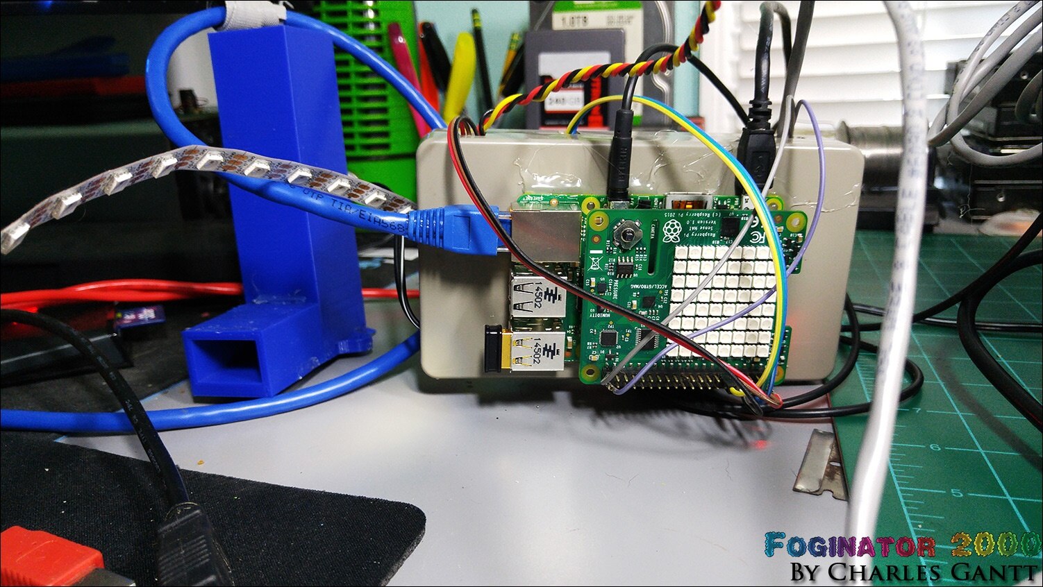
Unfortunately I was unable to fit the Raspberry Pi and Sense Hat inside this project enclosure as I had planned. I needed to keep the stack close to the peripheral boards, so I simply hot glued it to the back of the enclosure.
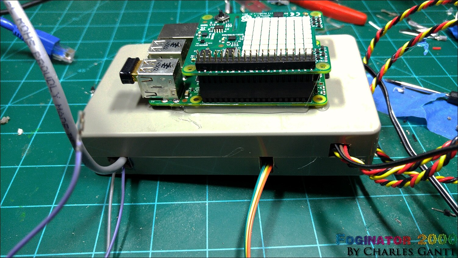
And a final shot of everything connected and ready to go! Note that the Raspberry Pi has been reoriented in this image. I forgot about the audio cable, and the original way I mounted it would not allow for it to be plugged in and the enclosure still be able to sit upright.
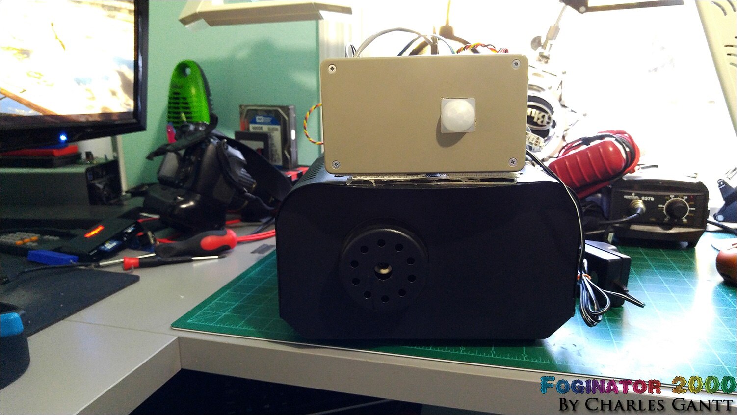
Due to a lack of time, I simply chose to mount the project enclosure on top of the fog machine using some velcro and hot glue. While this is not ideal, it does work quite well.
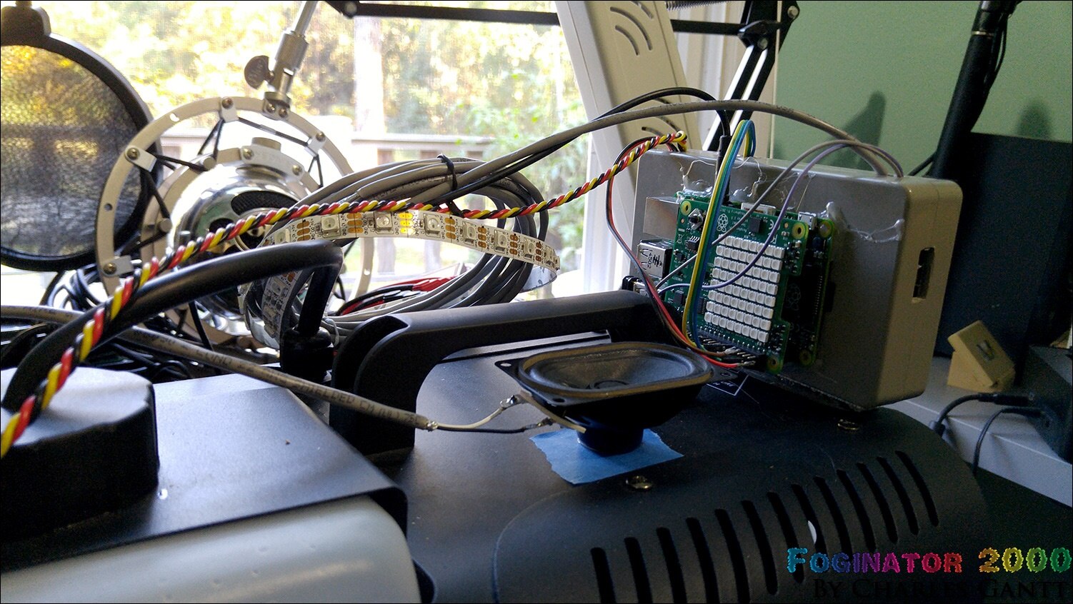
Looking at it from the back, you can see how starved for space this project is. Note the speaker. I found that for small things, blue tape on the fog machine’s surface helps hold the hot glue better.
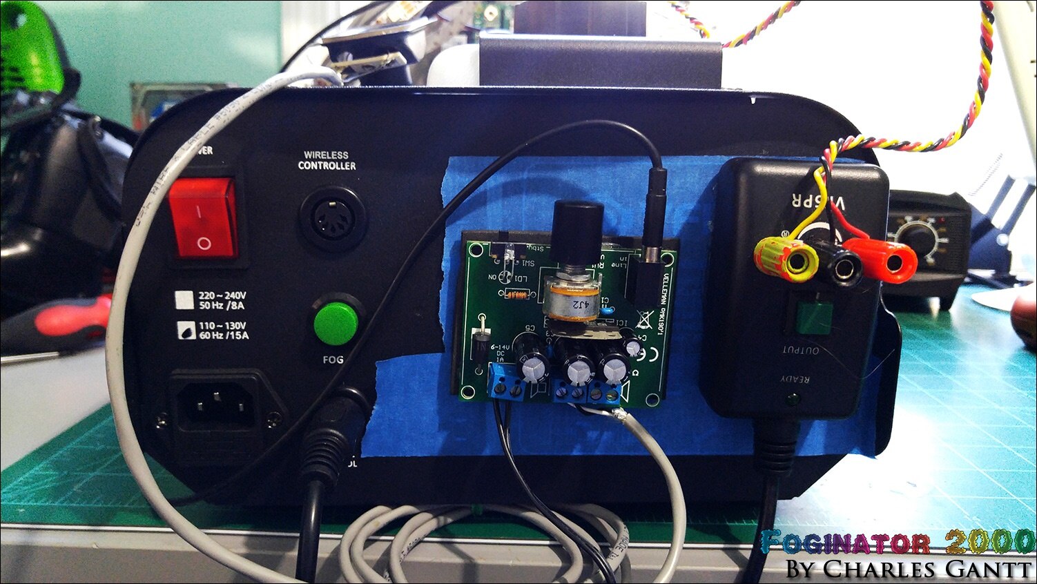
Looking at the back you can see how I mounted the audio amplifier and the fog machine remote switch. Again, blue tape came in handy here to help the hot glue stick better.
The Final Code
I have merged all of the code together and added in some print lines that help troubleshooting any issues. To record the data, you will need to sign up for an Initial State account, and then generate a new API key for your account. You can download this code from its Github Repository which can be found here.
__author__ = 'Charles Gantt'
# This code is part of the Foginator 2000 project developed for the Halloween15 Raspberry Pi Project event at Element14.com and can be found at http://bit.ly/foginator2000


import RPi.GPIO as GPIO
import time
import sys
from sense_hat import SenseHat
from ISStreamer.Streamer import Streamer


logger = Streamer(bucket_name="Foginator2000_Data_10/23/2015", access_key="zLahwAUqKbNKv6YvuT5JuO58EiUOavDa")


sense = SenseHat()
sense.clear()
sensing = True
fog_Armed = True


GPIO.setwarnings(False)
GPIO.setmode(GPIO.BCM)
GPIO.setup(4, GPIO.OUT)
GPIO.setup(17, GPIO.IN)
GPIO.setup(21, GPIO.OUT)


O = (0, 255, 0) # Green
X = (0, 0, 0) # Black


creeper_pixels = [
    O, O, O, O, O, O, O, O,
    O, O, O, O, O, O, O, O,
    O, X, X, O, O, X, X, O,
    O, X, X, O, O, X, X, O,
    O, O, O, X, X, O, O, O,
    O, O, X, X, X, X, O, O,
    O, O, X, X, X, X, O, O,
    O, O, X, O, O, X, O, O
]


black_pixels = [
    X, X, X, X, X, X, X, X,
    X, X, X, X, X, X, X, X,
    X, X, X, X, X, X, X, X,
    X, X, X, X, X, X, X, X,
    X, X, X, X, X, X, X, X,
    X, X, X, X, X, X, X, X,
    X, X, X, X, X, X, X, X,
    X, X, X, X, X, X, X, X
]


var = 0


def is_integration():
  while sensing == True:
        print "IS Start"
        temp = sense.get_temperature()
        temp = round(temp, 1)
        logger.log("Teperature C",temp)
        print "T1"
        humidity = sense.get_humidity()
        humidity = round(humidity, 1)
        logger.log("Humidity :",humidity)
        print "H1"
        pressure = sense.get_pressure()
        pressure = round(pressure, 1)
        logger.log("Pressure:",pressure)
        print "P1"
        logger.log("Trick Or Treat Event #",var)
        print "ToT Event Logged"
        sense.set_pixels(creeper_pixels)
        time.sleep(2)
        sense.set_pixels(black_pixels)
        sense.clear()
        print "IS Done"
        break


def fire_fog():
    while fog_Armed == True:
        print "Trick or Treat Event Sensed"
        print "Lights Start"
        GPIO.output(21,True)
        time.sleep(2)
        print "Relay Triggered"
        GPIO.output(4,True)
        time.sleep(10)
        print "Relay Disabled"
        GPIO.output(4,False)
        time.sleep(20)
        print "Lights Disabled"
        GPIO.output(21,False)
        is_integration()
        print "Trick or Treat Event Finished"
        time.sleep(10)
        print "Watching For Motion"
        break


while True:
    time.sleep(3)
    if GPIO.input(17)==True:
        var = var +1
        print ("var =", var)
        print "Motion Detected"
        fire_fog()
This code has been modified to run continuously while always looking for a motion trigger. To make this code run when you plug the Raspberry Pi in, you will need to set the python script to run on startup via the cron tab.
The Data
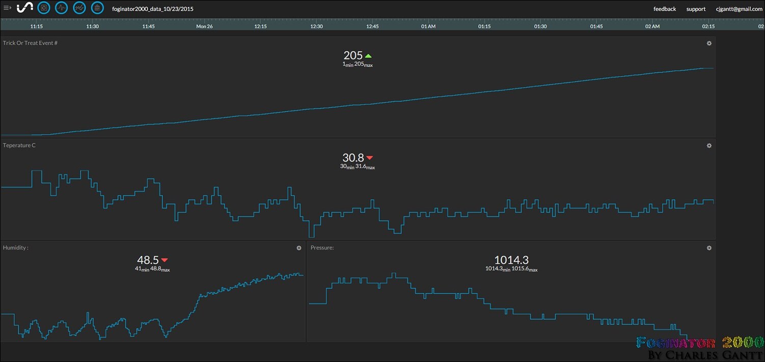
To recap, we are using the Sense Hat to record a few environmental data points including air temperature, humidity and air pressure. The Raspberry Pi then pushes that data to a remote server at Initial State, which then processes it, and displays it in nice graphs, and other visualizations. I have also added a fourth metric called “Trick or Treat Event” that simply increments by one every time a motion event is detected. As you can see in the image below, everything seems to be working perfectly. You can check out the full stream here.
In the video below, you can see me walking into the room, and the sensor tripping when the fog fires. If I have some free time on Halloween before the Trick or Treaters arrive, I am going to add in another meter or so of Neopixel strips to increase the illumination.
That is going to wrap up this installment. I will be back in just a few days with a complete wrap up of this whole project and the results from Halloween night!
- Project Introduction
- Fog Controller Hardware and Test
- Environment Sensing Coding & Testing
- Ambient Audio Hardware and Coding
- Lighting Coding and Testing
- Final Assembly and Testing
Originally published by Charles Gantt on Element14 Community