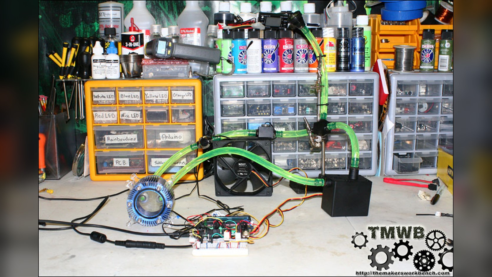
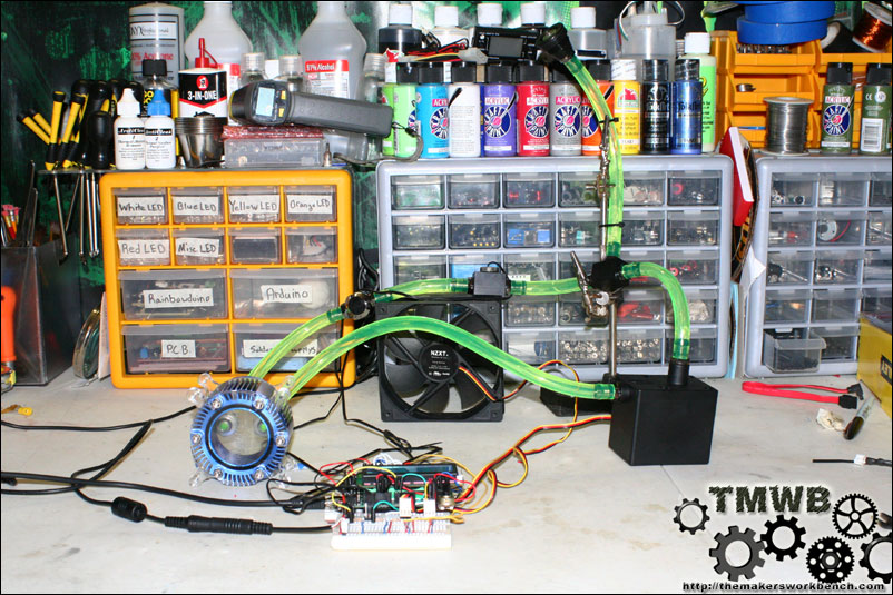
This is part of my Arduino Controlled PC Liquid Cooling Information Center I have been working on and I thought I would share it here since there have been a few threads on arduino.cc and seeedstudio.com on how to read water flow rate in liters per hour using the Water Flow Sensor found in the Seeed Studio Depo. It uses a simple rotating wheel that pulses a hall effect sensor. By reading these pulses and implementing a little math, we can read the liquids flow rate accurate to within 3%. The threads are simple G1/2 so finding barbed ends will not be that hard. I found some at Lowes for $1.89 each.
Parts Required
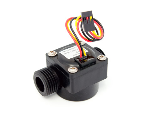
You will need
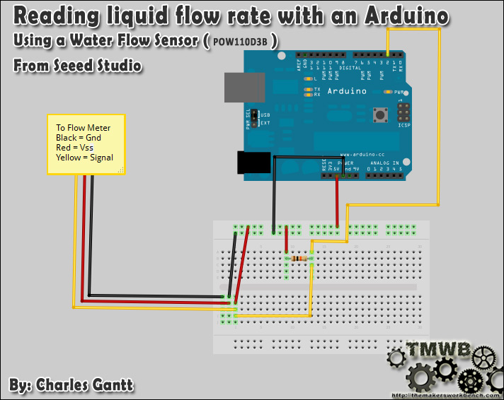
Wiring up the Water Flow Sensor is pretty simple. There are 3 wires: Black, Red, and Yellow.
- Black to the Seeeduino's ground pin
Red to Seeeduino's 5v pin
The yellow wire will need to be connected to a 10k pull up resistor.and then to pin 2 on the Seeeduino.
Here is a fritzing diagram I made to show you how to wire it all up.
Once you have it wired up you will need to upload the following code to your Seeeduino. Once it is uploaded and you have some fluid flowing through the Water Flow Sensor, you can open the serial monitor and it will display the flow rate, refreshing every second.
// reading liquid flow rate using Seeeduino and Water Flow Sensor from Seeedstudio.com
// Code adapted by Charles Gantt from PC Fan RPM code written by Crenn @thebestcasescenario.com
// http:/themakersworkbench.com http://thebestcasescenario.com http://seeedstudio.com

volatile int NbTopsFan; //measuring the rising edges of the signal
int Calc;
int hallsensor = 2;    //The pin location of the sensor

void rpm ()     //This is the function that the interupt calls
{
  NbTopsFan++;  //This function measures the rising and falling edge of the

hall effect sensors signal
}
// The setup() method runs once, when the sketch starts
void setup() //
{
  pinMode(hallsensor, INPUT); //initializes digital pin 2 as an input
  Serial.begin(9600); //This is the setup function where the serial port is

initialised,
  attachInterrupt(0, rpm, RISING); //and the interrupt is attached
}
// the loop() method runs over and over again,
// as long as the Arduino has power
void loop ()
{
  NbTopsFan = 0;	//Set NbTops to 0 ready for calculations
  sei();		//Enables interrupts
  delay (1000);	//Wait 1 second
  cli();		//Disable interrupts
  Calc = (NbTopsFan * 60 / 7.5); //(Pulse frequency x 60) / 7.5Q, = flow rate

in L/hour
  Serial.print (Calc, DEC); //Prints the number calculated above
  Serial.print (" L/hour\r\n"); //Prints "L/hour" and returns a  new line
}
I hope this helps someone out! Thank's to Seeed Studio for hooking me up with a sensor so I could develop this tutorial.