Originally published on the element14 Community by Charles Gantt. This archived edition preserves the original project text, images, and video links.
Part 1: Trick or Trivia Halloween Candy Dispenser #001 - Project Introduction

Halloween has always been one of my favorite holidays, so much so that I founded a business that makes professional-grade props and controllers for Haunted Houses. This naturally led to Element14 asking me to create a couple of projects that were easy enough for the community to follow along and replicate the project at home. For my first project, I am going to be creating a very unique halloween candy dispenser that utilizes a trivia game to dispense the candy.
The Concept
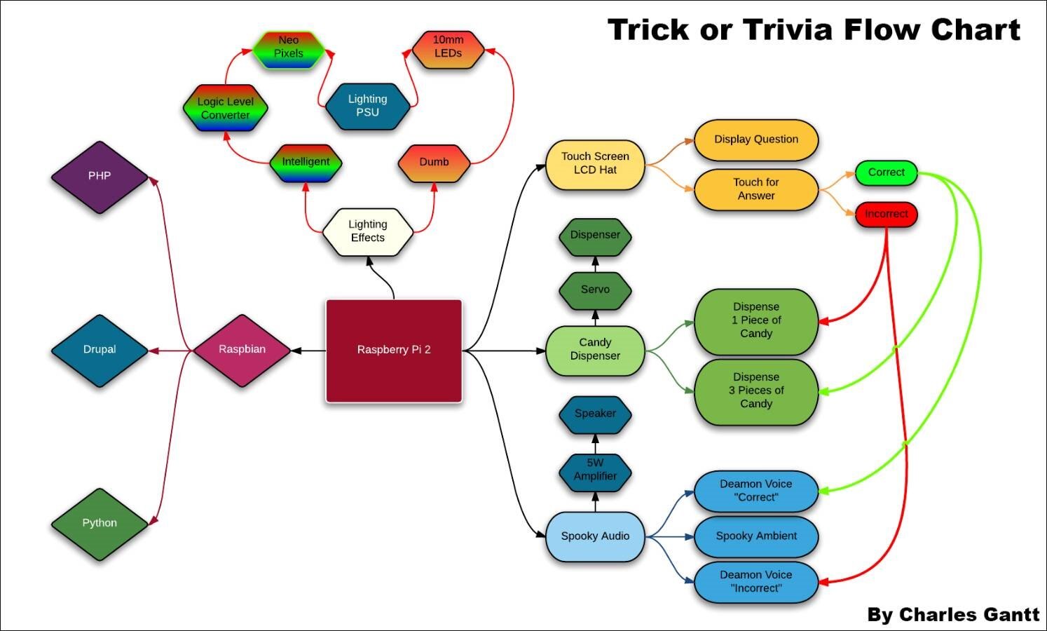
The idea behind this project is to create a halloween-based candy dispenser that requires the trick or treaters to answer a simple Halloween trivia question in order to obtain the maximum amount of candy. When the trick or treater steps in front of the candy cauldron, the Raspberry Pi will display a trivia question on the touch-screen LCD hat along with four answers. If the trick or treater gets the answer right, he or she will be rewarded with three pieces of candy. If the trick or treater gets the answer wrong, they will only receive a single piece of candy.
In addition to this functionality, the Raspberry Pi will play a “Correct” audio event if the answer is correct. Neopixel LEDs will illuminate and flash a pattern. If the answer is incorrect, the Raspberry Pi will play an “Incorrect” audio event and flash a different pattern on the neopixel LEDs. The Raspberry Pi will also control several “ambient” LEDs around the base and in another area of the device.
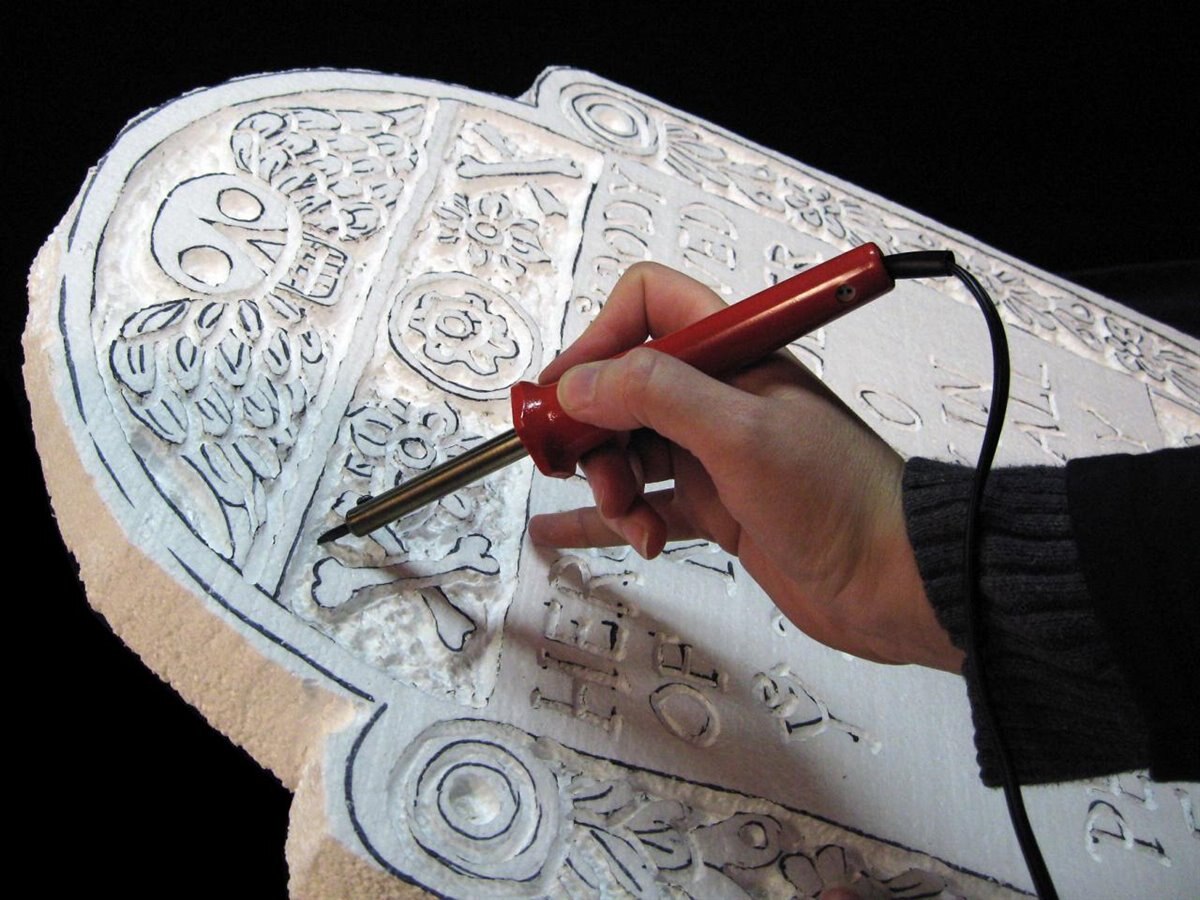
DIY Foam Tombstone. Image courtesy DiyNetwork.com
At the moment, I am planning on building a custom tombstone from pink insulation foam, and using either my X-Carve CNC to carve it out, or using a combination of an Exacto knife and an old soldering iron to carve and shape the tombstone. Originally I had plans on using a 4-foot to 5-foot Frankenstein statue, but was unable to locate one that was within my budget of $100 for the physical prop.
I will either be utilizing Drupal or straight PHP and Python to build the trivia interface. Alternatively I may use a combo of all three to get the job done. Basically I need to have the LCD display a question and have touch buttons for four different answers. When the correct answer is chosen, the Pi will need to activate the candy dispenser and kick out the appropriate number of pieces of candy.
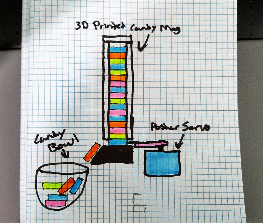
The candy dispenser will be a simple magazine design that holds Starburst candies which will be pushed out and dropped into a cauldron by a simple hobby servo. I will be 3D Printing the candy magazine and dispenser mechanism in the sake of saving some time, but I will include the sketchup design files so that those of you following at home can figure out how to construct this from wood, foam core, styrene, or some other material you are familiar with.
The Hardware.
Most of the electronic components for this project can be found in the Trick or Trivia kit found here at Element14, with some parts needing to be purchased from MCM Electronics.
This whole project is based around the new Raspberry Pi 7-inch DSI Touch Screen DisplayRaspberry Pi 7-inch DSI Touch Screen Display. This new screen is purposely designed for the Raspberry Pi, and utilizes the DSI port on the Raspberry Pi itself which frees up the HDMI port for other multimedia duties.
Newark.com
Newark Part No. | Notes | Qty | Manufacturer / Description |
36K745036K7450 | 5v coil relay | 1 | OMRON SPDT, 5 VDC, 10A Relay |
38Y646738Y6467 | RPi | 1 | RASPBERRY PI 2, MODEL B, |
38Y647038Y6470 | SD Card | 1 | RASPBERRY PI 8GB NOOBS MICRO SD CARD |
44W493244W4932 | PSU | 1 | POWER SUPPLY 5V, 1A |
06W104906W1049 | USB Cable | 1 | USB A PLUG TO MICRO USB B PLUG |
53W628553W6285 | WiFi Dongle | 1 | ADAFRUIT USB WIFI MODULE |
26Y846026Y8460 | Mood LEDs | 1 | ADAFRUIT NEOPIXEL Strip 1M 144LED |
26Y845526Y8455 | Ambient LED | 1 | ADAFRUIT NEOPIXEL STICK |
40P118440P1184 | Speaker | 1 | VISATON SPEAKER, 20 kHz, 8OHM, 4W |
87K702787K7027 | 10mm LEDs | 5 | LED, RED, T-3 (10MM) |
58K382758K3827 | Resistors | 5 | METAL FILM RESISTOR, 220 OHM, 250mW, 1% |
10M846410M8464 | Flyback Diode for Relay | 1 | 1N40011N4001 Rectifier Diode 50 V 1 A |
34C109234C1092 | PSU Vreg | 1 | 7805 LINEAR VOLTAGE REGULATOR, 5V, TO-220-3 |
58K379658K3796 | PSU LED Resistor | 1 | METAL FILM RESISTOR, 1KOHM, 250mW, 1% |
17F216517F2165 | PSU Filter Cap | 1 | CERAMIC CAPACITOR 0.1UF, 50V, X7R, 20% |
69K794969K7949 | PSU Filter Cap | 1 | ELECTROLYTIC CAPACITOR 47UF, 50V, 20% |
69K790769K7907 | PSU Filter Cap | 1 | ELECTROLYTIC CAPACITOR 100UF, 50V, 20%, |
14N941814N9418 | PSU LED | 1 | RED, T-1 3/4 (5MM) |
| 49Y171249Y1712 | 7-Inch Touch Screen | 1 | Raspberry Pi 7" Touch Screen Display |
MCM Electronics
MCM Part No. | Notes | Qty | Manufacturer / Description |
Servo | 1 | 28-17452 - TowerPro SG-5 Standard Servo | |
Audio Amp | 1 | Audio Amplifier Kit 2 X 5W RMS | |
Logic Level Converter | 1 | 8 Channel Logic Level Converter | |
Project Enclosure | 1 | ABS Case Gray - 5-5/8" x 3-1/8" x 1-3/16" |
As you can see, this project has quite a few components that are required, but there are a few that are totally optional. If you wanted to save a little money, you could purchase the 30 or 60 pixel per meter strips of neopixels and save a good bit. Also, you could forgo the NeoPixels all together and save close to $100.
In addition to these parts that you will need to order, you will also need to pick up two 4-foot x 8-foot sheets of 1-inch thick rigid home insulation foam from your local hardware store. If you live in a colder climate than I do, then you might be able to find rigid insulation foam up to three inches thick, and could skip having to laminate foam together. You will also need a few yards of 3-conductor wire, or 100 feet or more of single conductor wire that will need to be paired up for the NeoPixel and Audio components. Finally, you will need an 3.5mm audio extension cable, a ethernet patch cable, or a wifi router. A soldering iron will be needed to assemble parts of the kit, as well as to carve some of the tombstone. Other handtools such as screwdrivers, pliers, and wire cutters are needed.
If you have any questions, suggestions, or comments in general, please feel free to leave them below, or by sending me a private message here at Element14. If anyone chooses to follow along at home and build their own Trick or Trivia Candy Dispenser, please post photos, and even blog post if you can as I am very excited to see your work!
I will be posting an update every week with the project wrapping up on October 16th. I have taken the liberty of laying out each of the weekly milestones below.
Project Introduction
Building The Trivia Interface
- Interfacing Ambient and Triggered Audio Events
- Building The Candy Dispenser & Servo Coding
- Carve Foam Tombstone
- October 24th - Assembly and Testing
- October 28th - Project Wrap-up
Originally published by Charles Gantt on Element14 Community
Part 2: Trick or Trivia Halloween Candy Dispenser #002 - Building The Trivia Interface

Hello everyone! It’s been a week and I have been working hard at designing and writing the trivia interface for this project, and I am proud to say that after an absence of more than five years from Python, I was successful in getting a decent looking GUI built. Unfortunately I have yet to figure out how I will be randomizing the questions that the device ask trick-or-treaters, but that is something I can work on later in the project. So let’s jump in and take a look at how I created the trivia interface.
In my first post, I mentioned that I had planned on using the Drupal CMS to build the trivia interface. After some conversation with another Drupal developer, I came to the conclusion that using a PHP-based framework and building a database was way overkill when I wanted to just display a few questions on a screen. So I decided to just write the whole trivia interface in Python, a language I have not touched in more than five years. Unfortunately my entire Python experience was in the command line, and I had never tried writing a GUI before.
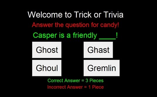
After some research I found out that it is extremely easy to create a simple, low-level user interface in Python by using a GUI library named Tkinter. For those of you who have never heard of Tkinter (like me), it’s Python's de-facto standard GUI (Graphical User Interface) package. It is a thin object-oriented layer on top of Tcl/Tk. Using Tkinter I was easily able to create a nice full-screen application that would clearly present the question and its answer buttons to the user.
Installing The Raspberry Pi 7-InchTouch Screen
Before I show you the interface and the code that created it, let’s take a look at what we will be displaying the code on. Element14 sent me the brand new Raspberry Pi 7-inch touch-screen LCDRaspberry Pi 7-inch touch-screen LCD to use in this project, and after spending a couple of weeks with this screen, all I can say is WOW. I have used several different screens with the Raspberry PiRaspberry Pi, and Beaglebone BlackBeaglebone Black boards, and none has been as easy as this screen was to use.
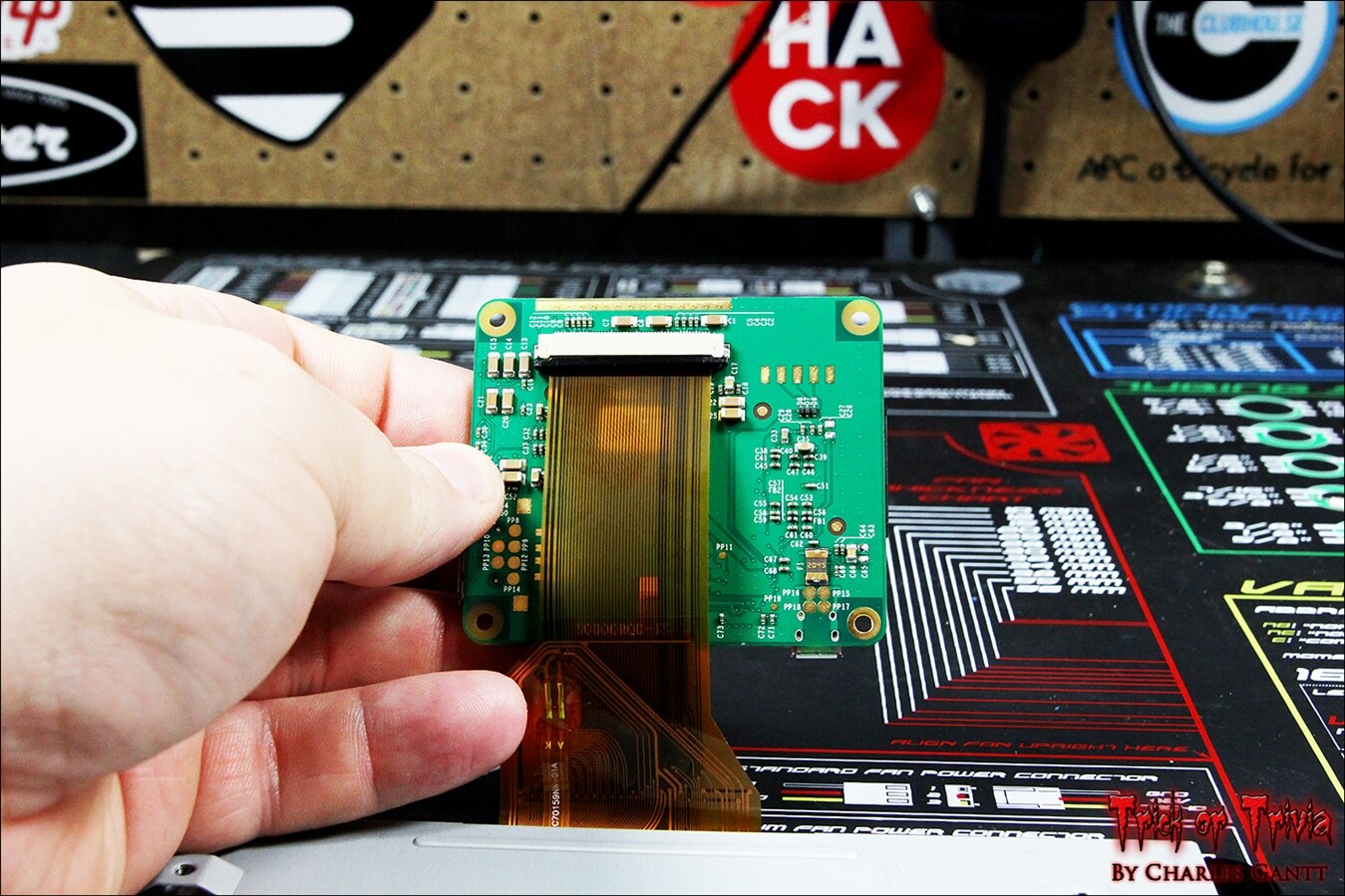
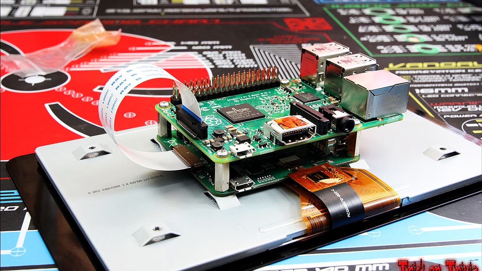
Getting the Raspberry Pi 7-inch Touch Screen up and running is as simple as connecting the large ribbon cable to the back of the driver board, and then securing the driver board to the screen with the provided hardware.
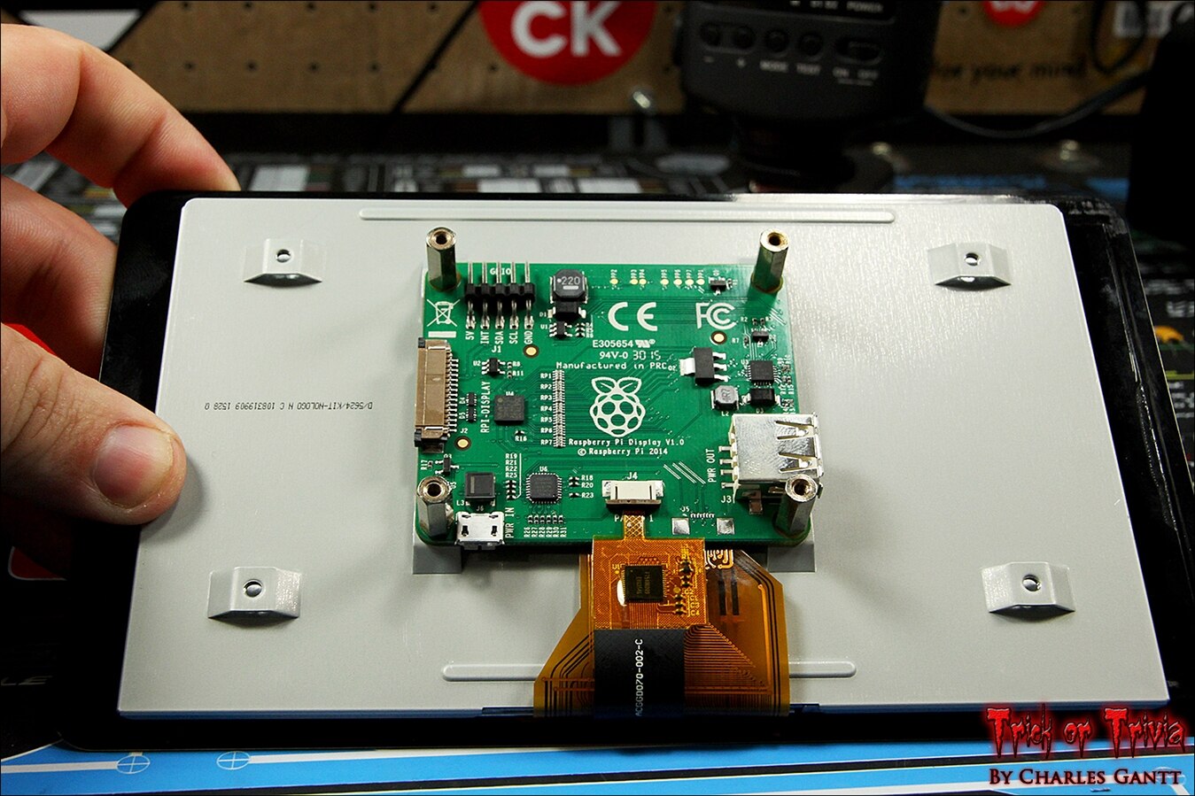
With the driver board mounted to the LCD screen, connect the smaller ribbon cable to the driver board. I found it was easier to do it this way since I have larger fingers.
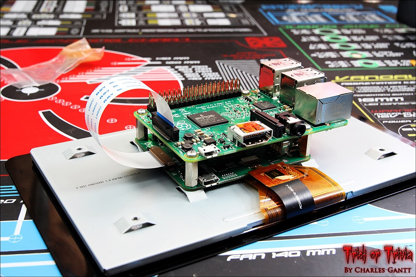
With thetwo LCD ribbon cables connected, mount the Raspberry Pi to the stand-offs, and then connect the DSI cable to both boards.
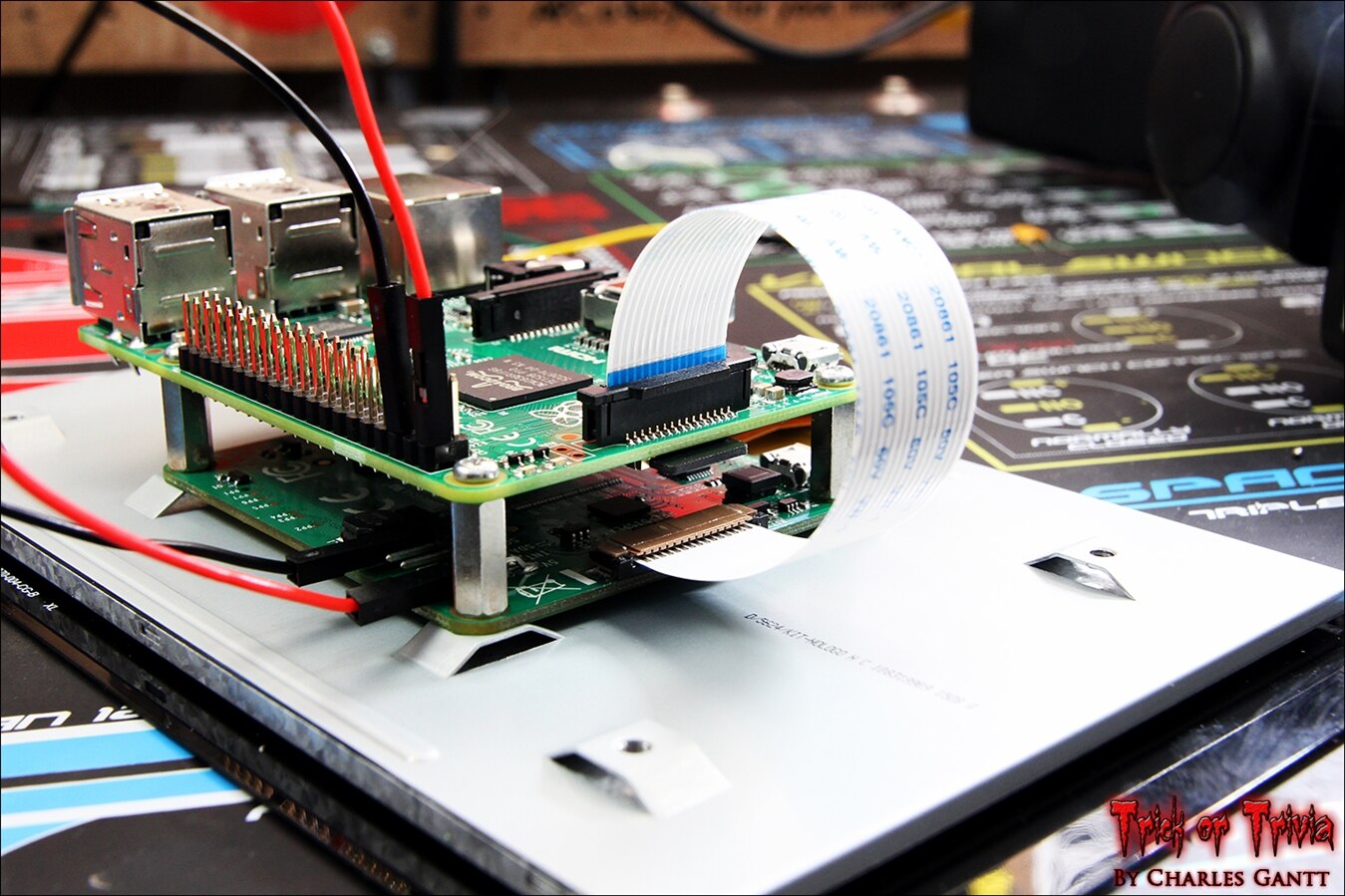
Now connect the two power jumper wires to both boards as shown in the above image. You will also want to insert the SD card into the Raspberry Pi. If you are running the latest version of raspbian, you can now plug a 5V 2A power source into the LCD screen’s driver board. If you do not have a 5V 2A power source, you can remove the power wires that connect the two boards, and then connect a single 5V 1A power source to the Raspberry Pi and One to the LCD screen’s driver board.
You will have to connect your Raspberry Pi to video source via the HDMI port for this process, or SSH into the Pi if you know it’s IP address. If you are using the NOOBs SD card that comes with the kit for this tutorial, you will have to update to the latest Raspbian, as the one installed on it is out of date.
To see which version of Raspbian your Pi is running, use the following command in the terminal:
uname -a
Which should return something that looks like this.
Linux raspberrypi 4.1.6-v7+ #810 SMP PREEMPT Tue Aug 18 15:32:12 BST 2015 armv7l GNU/Linux
If your version of Raspbian is out of date, run the following commands in the terminal:
sudo apt-get update
Then
sudo apt-get upgrade -y
With the update and upgrades ran, you can now restart your Raspberry Pi, and the LCD screen should now work and display the login screen.
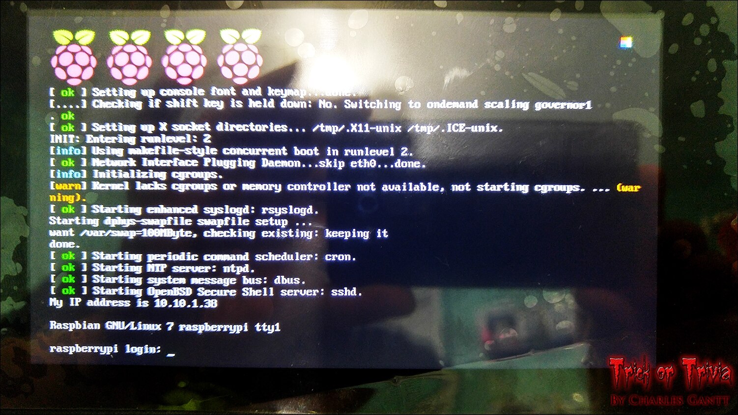
Enter the desktop GUI by typing the following command after logging in.
startx
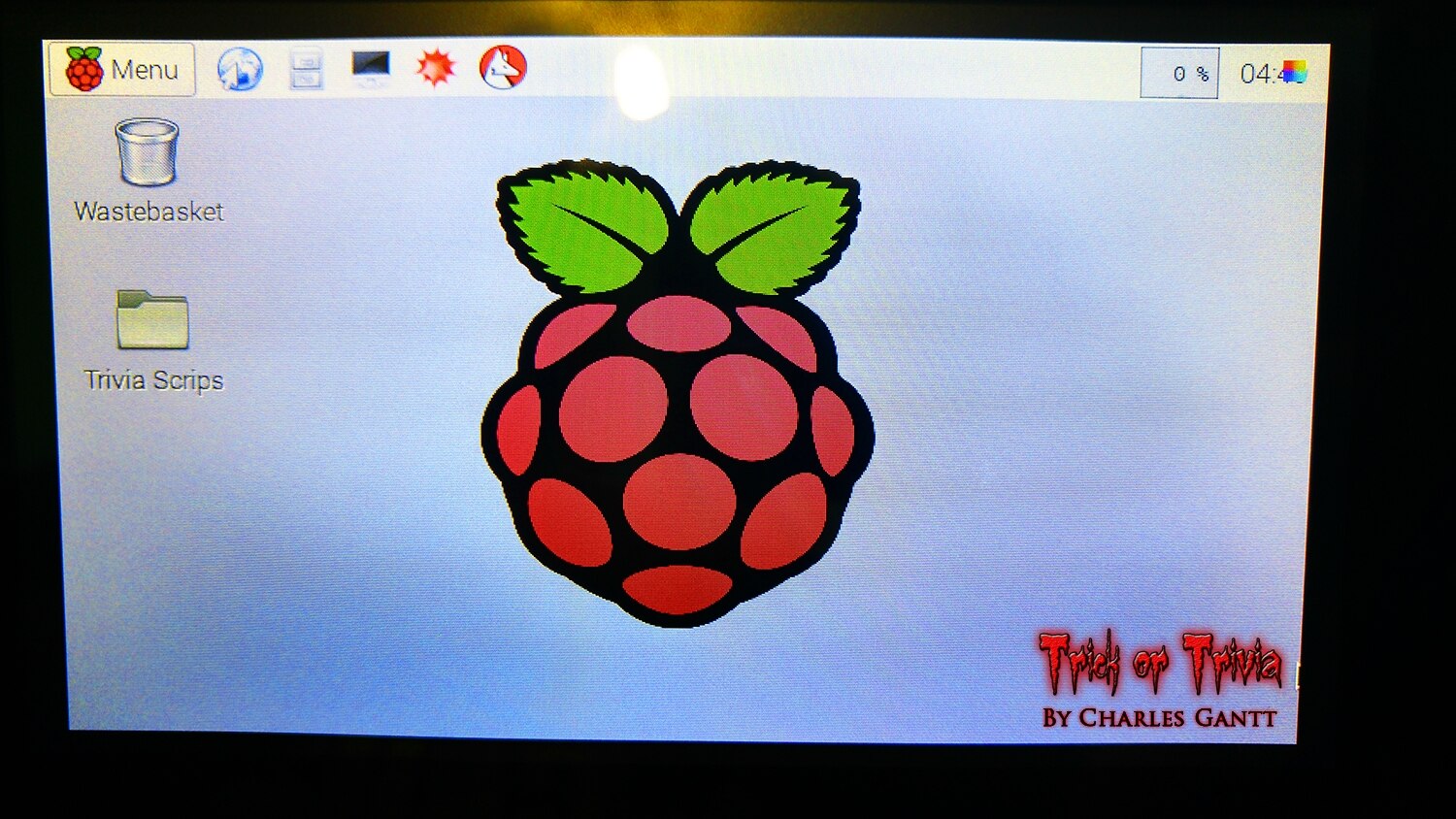
Now that you are on the desktop, let’s look at how I built the trivia GUI.
GUI Build UsingTkinter

As I mentioned above, I decided to write my own GUI instead of using a heavy framework like Drupal to create a simple quiz interface. I looked at a few options and finally decided on a GUI solution that was already built into Python called Tkinter. I chose this because it was very lightweight which would save loading times, and because it seemed very simple to use.
The Knowledge
One of the biggest sellers for me on Tkinter was the sheer amount of documentation that is available online. New Mexico Tech has a great Tkinter reference on their website which was very helpful when troubleshooting, but the best resource I found was a series of Videos on YouTube from a user named TheNewBoston. I would highly recommend heading to his channel and watching his tutorial series on using Tkinter.
I ended up watching the entire series, but if you only have time to watch a few, everything up to video six will give you the knowledge needed to complete this project. Watch the videos if you are following along at home, and check out my code below which I have broken out to better explain what each section does.
The Code
We need to import Tkinter, the Raspberry Pi GPIO as GPIO, Time, and system libraries.
from Tkinter import *
import RPi.GPIO as GPIO
import time
import sys
Here we set up the GPIO pins. For the purpose of this tutorial I turn GPIO warnings to off. Then we need to set the GPIO Pinout to the BCM layout. Finally we need to define two output pins that will turn on a pair of LEDs.
GPIO.setwarnings(False)
GPIO.setmode(GPIO.BCM)
GPIO.setup(26, GPIO.OUT)
GPIO.setup(19, GPIO.OUT)
For those of you who do not know, the Raspberry PI’s GPIO sins can be configured two different ways, GPIO.board and GPIO.bcm. When setting the GPIO pins mode, you are telling it what numbering scheme your code will be adhering too. Unfortunately the pin numbering between each of the different modes changes on various models and revisions of the Raspberry PI. So if you are not running a Model B+ or Raspberry Pi 2, you will need to search the internet for the proper pinouts for the mode you select.
- The GPIO.BOARD option specifies that you are referring to the pins by the number of the pin the the plug - i.e the numbers printed on the board (e.g. P1) and in the middle of the diagram below.
- The GPIO.BCM option means that you are referring to the pins by the "Broadcom SOC channel" number, these are the numbers after "GPIO" in the green rectangles around the outside of the diagram below.
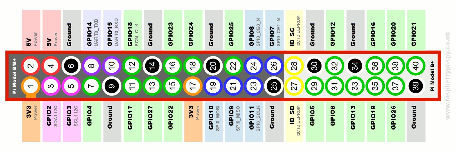
Raspberry Pi B+ and Raspberry Pi 2 GPIO Pinout.
We need to set the state to True
state = True
This section defines a function called blink_led. At the end of this script I add a sys.exit line that is executed three seconds after I turn off the GPIO pin for the last time. This exits out of the quiz script, allowing us to reset for the next trick-or-treater.
def blink_led():
# endless loop, on/off for 1 second
    while True:
        GPIO.output(26,True)
        time.sleep(1)
        GPIO.output(26,False)
        time.sleep(1)
        GPIO.output(26,True)
        time.sleep(1)
        GPIO.output(26,False)
        time.sleep(1)
        GPIO.output(26,True)
        time.sleep(1)
        GPIO.output(26,False)
        time.sleep(1)
        GPIO.cleanup()
        time.sleep(3)
        sys.exit()
This section sets up another function that blinks the same pattern, but this time we name the function blink_led_2.
def blink_led_2():
# endless loop, on/off for 1 second
    while True:
        GPIO.output(19, True)
        time.sleep(1)
        GPIO.output(19, False)
        time.sleep(1)
        GPIO.output(19, True)
        time.sleep(1)
        GPIO.output(19, False)
        time.sleep(1)
        GPIO.output(19, True)
        time.sleep(1)
        GPIO.output(19, False)
        time.sleep(1)
        GPIO.cleanup()
        time.sleep(3)
        sys.exit()
Now we need to set up Tkinter. The first thing we need to do is set up a basic box that will hold the elements of our GUI. We do this by telling the program that root=Tk().
root = Tk()
Now we need to set the window to not have a border, title, or any of the normal minimize, maximize, and close buttons.
root.overrideredirect(True)
This line tells the program to set the window to full screen and auto size it to the screens resolution.
root.geometry("{0}x{1}+0+0".format(root.winfo_screenwidth(), root.winfo_screenheight()))
Now we need to tell the program to set the focused window to this one.
root.focus_set()
We also need to set the window’s background to black.
root.configure(background='black')
With the basic GUI window setup we can move on to setting up the elements that will appear in the z. This consist of three labels on top that span three rows of a grid, followed by two answer buttons on the next row spaced apart by two columns, and another row with two buttons and the same spacing below it. Finally we need to add two more labels to the bottom that describe what the rewards are for correct and incorrect answers. You will see that I have styled the elements inline with basic styling options, and placed the elements using Tkinter's .grid Geometry Manager.
Setting up the Labels.
In each of these three labels you can see that I have placed them in the root box, and included font, font size, background color, and foreground color attributes. and the set each of the labels to display using the .grid method followed by some placement style and padding attributes.
label_1 = Label(root, text="Welcome to Trick or Trivia", font=("Helvetica", 36), bg="black", fg="white")
label_1.grid(columnspan=6,padx=(100, 10))
label_2 = Label(root, text="Answer the question for candy!", font=("Helvetica", 28), bg="black", fg="red")
label_2.grid(columnspan=6, pady=5, padx=(100, 10))
label_3 = Label(root, text="Casper is a friendly ____!", font=("Helvetica", 32), bg="black", fg="green")
label_3.grid(columnspan=6, pady=5, padx=(100, 10))
Setting up the Buttons
Just like the Label elements, I defined the buttons by placing them into the root window, adding text, and including attributes for font type and font size. Here is a reference (http://effbot.org/tkinterbook/button.htm). What makes the buttons special is the “command” attribute I included at the end of the button setup line. This calls the function it names, which in our case is one of the two blink_led functions we wrote earlier. Finally I displayed the button using the .grid method with some styling attributes.
button_1 = Button(root, text="Ghost", font=("Helvetica", 36), command=blink_led)
button_1.grid(row=4, column=2, pady=5, padx=(100, 10))
button_2 = Button(root, text="Ghast", font=("Helvetica", 36), command=blink_led_2)
button_2.grid(row=4, column=4, sticky=W, padx=(100, 10))
button_3 = Button(root, text="Ghoul", font=("Helvetica", 36), command=blink_led_2)
button_3.grid(row=5, column=2, pady=5, padx=(100, 10))
button_4 = Button(root, text="Gremlin", font=("Helvetica", 36), command=blink_led_2)
button_4.grid(row=5, column=4, sticky=W, padx=(100, 10))
Finally I added two more labels with the same styling and placement attributes as before.
label_4 = Label(root, text="Correct Answer = 3 Pieces", font=("Helvetica", 20), bg="black", fg="green")
label_4.grid(columnspan=6, padx=(100, 10))
label_5 = Label(root, text="Incorrect Answer = 1 Piece", font=("Helvetica", 20), bg="black", fg="red")
label_5.grid(columnspan=6, padx=(100, 10))
Finally we need to tell the program to stay in the event loop until we close the window.
root.mainloop()
Putting It All Together
Here is what the code looks like as a whole. You can download this code from my Github repo for this project or by clicking here.
from Tkinter import *
import RPi.GPIO as GPIO
import time
import sys


GPIO.setwarnings(False)
GPIO.setmode(GPIO.BCM)
GPIO.setup(26, GPIO.OUT)
GPIO.setup(19, GPIO.OUT)


state = True


def blink_led():
# endless loop, on/off for 1 second
    while True:
        GPIO.output(26,True)
        time.sleep(1)
        GPIO.output(26,False)
        time.sleep(1)
        GPIO.output(26,True)
        time.sleep(1)
        GPIO.output(26,False)
        time.sleep(1)
        GPIO.output(26,True)
        time.sleep(1)
        GPIO.output(26,False)
        time.sleep(1)
        GPIO.cleanup()
        time.sleep(3)
        sys.exit()


def blink_led_2():
# endless loop, on/off for 1 second
    while True:
        GPIO.output(19, True)
        time.sleep(1)
        GPIO.output(19, False)
        time.sleep(1)
        GPIO.output(19, True)
        time.sleep(1)
        GPIO.output(19, False)
        time.sleep(1)
        GPIO.output(19, True)
        time.sleep(1)
        GPIO.output(19, False)
        time.sleep(1)
        GPIO.cleanup()
        time.sleep(3)
        sys.exit()


root = Tk()
root.overrideredirect(True)
root.geometry("{0}x{1}+0+0".format(root.winfo_screenwidth(), root.winfo_screenheight()))
root.focus_set()  # <-- move focus to this widget
root.configure(background='black')
root.config(cursor="none")


label_1 = Label(root, text="Welcome to Trick or Trivia", font=("Helvetica", 36), bg="black", fg="white")
label_1.grid(columnspan=6,padx=(100, 10))
label_2 = Label(root, text="Answer the question for candy!", font=("Helvetica", 28), bg="black", fg="red")
label_2.grid(columnspan=6, pady=5, padx=(100, 10))


label_3 = Label(root, text="Casper is a friendly ____!", font=("Helvetica", 32), bg="black", fg="green")
label_3.grid(columnspan=6, pady=5, padx=(100, 10))


button_1 = Button(root, text="Ghost", font=("Helvetica", 36), command=blink_led)
button_1.grid(row=4, column=2, pady=5, padx=(100, 10))


button_2 = Button(root, text="Ghast", font=("Helvetica", 36), command=blink_led_2)
button_2.grid(row=4, column=4, sticky=W, padx=(100, 10))


button_3 = Button(root, text="Ghoul", font=("Helvetica", 36), command=blink_led_2)
button_3.grid(row=5, column=2, pady=5, padx=(100, 10))


button_4 = Button(root, text="Gremlin", font=("Helvetica", 36), command=blink_led_2)
button_4.grid(row=5, column=4, sticky=W, padx=(100, 10))


label_4 = Label(root, text="Correct Answer = 3 Pieces", font=("Helvetica", 20), bg="black", fg="green")
label_4.grid(columnspan=6, padx=(100, 10))


label_5 = Label(root, text="Incorrect Answer = 1 Piece", font=("Helvetica", 20), bg="black", fg="red")
label_5.grid(columnspan=6, padx=(100, 10))


root.mainloop()
Copy and paste this code into a new file on your Raspberry Pi’s desktop, or from the command line enter the following commands.
cd Desktop
sudo nano TrickorTriviaQuiz.py
Then right click to paste the copied code into the new file, and exit nano.
Setting up the LEDs
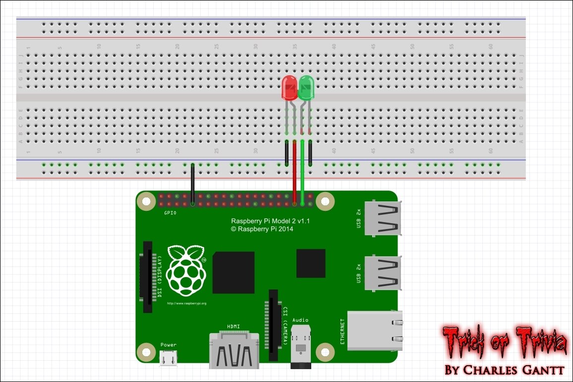
Follow the diagram above and wire up your LEDs to GPIO pins 19 and 26 . Since the Pi’s GPIO pins output a 3.3v signal, you do not need resistors if you are using a single red, green LEDs.
Running the program
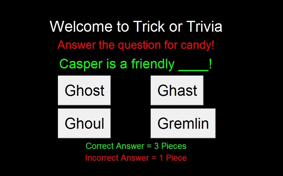
Now from the desktop, open the terminal (if you were not in the GUI or pasting the code remotely. With the terminal open, navigate to the desktop directory and enter the following command to run your new quiz program.
sudo nano TrickorTrivia.py
The trivia screen should pop up like in the video below. If you select a correct answer, then the green LED will illuminate and flash three times. If an incorrect answer is selected, then the red LED will illuminate and flash three times.
The LEDs used in this tutorial are just for troubleshooting purposes, and are not part of the kit. You can use any LEDs you have laying around, or two of the red 10mm LEDs included in the kit. In a future update, I will show you how to write a function that rotates a servo via the GPIO pins and we will replace the blink_led calls with this. For now this proves that the quiz script works, and that we are okay moving forward with the next step in the project. Check back next week for another update, and until then, Hack the World and Make Awesome!
Project Introduction
Building The Trivia Interface
- Interfacing Ambient and Triggered Audio Events
- Building The Candy Dispenser & Servo Coding
- Carve Foam Tombstone
- October 24th - Assembly and Testing
- October 28th - Project Wrap-up
Originally published by Charles Gantt on Element14 Community
Part 3: Trick or Trivia Halloween Candy Dispenser #003 - Interfacing Ambient and Triggered Audio Events

Welcome back to the Trick or Trivia Blog. In this installment, I am going to show you how I managed to get the audio portion of this project up and running. I hit a slight bump in the road shortly after setting down to figure all of this out. I had planned on having several different layers of sound playing at once, but have only managed to get a background and foreground set of layers working together, and I think that will be enough.
I had originally planned on running the background / ambient audio from within the same python script that the main program was in, but I slowly realized that this was not only a bad idea, but it simply might not work with the way I plan on randomizing questions. I will confess that I spent more than a few hours trying to get the ambient audio working in a subprocess, and several other parallel processing methods, but failed miserably, and decided to run the ambient audio another way. I decided to take the easy route, and just write a separate python script that would allow me to play the ambient audio loop when the Raspberry PiRaspberry Pi booted up. By removing this process from my main TrickOrTrivia.py script, I was able to move on to getting the audio working with the buttons. Before we get into how I did that, let’s take a quick look at the hardware that is used in this installment of Trick Or Trivia.
The Hardware
Below you will see a list of the hardware used to build out the audio portion of this project. In addition to these components, you will need the following tools: a soldering iron, solder, flush cutters, wire strippers, 3-10 feet of 2-pair cable, and a 6-inch or longer 3.5mm to 3.5mm audio extension cable.
Newark.com
Newark Part No. | Notes | Qty | Manufacturer / Description |
38Y646738Y6467 | RPi | 1 | RASPBERRY PI 2, MODEL B, |
38Y647038Y6470 | SD Card | 1 | RASPBERRY PI 8GB NOOBS MICRO SD CARD |
44W493244W4932 | PSU | 1 | POWER SUPPLY 5V, 1A |
06W104906W1049 | USB Cable | 1 | USB A PLUG TO MICRO USB B PLUG |
53W628553W6285 | WiFi Dongle | 1 | ADAFRUIT USB WIFI MODULE |
40P118440P1184 | Speaker | 1 | VISATON SPEAKER, 20 kHz, 8OHM, 4W |
| 49Y171249Y1712 | 7-Inch Touch Screen | 1 | Raspberry Pi 7" Touch Screen Display |
MCM Electronics
MCM Part No. | Notes | Qty | Manufacturer / Description |
Audio Amp | 1 | Audio Amplifier Kit 2 X 5W RMS |
Building the Velman 2x5W Amplifier
One of the major things that I have learned from being in the Haunted Attraction industry is that lighting and sound are two of the biggest “make it or break it” features of a successful prop. When I was putting together the kit for this project, I knew I wanted audio to be a big part of the project. The Raspberry Pi makes it quite easy to add audio to a project, but unfortunately, unless your project makes use of earbuds, you will need to add an amplifier to the project to drive more powerful speakers.
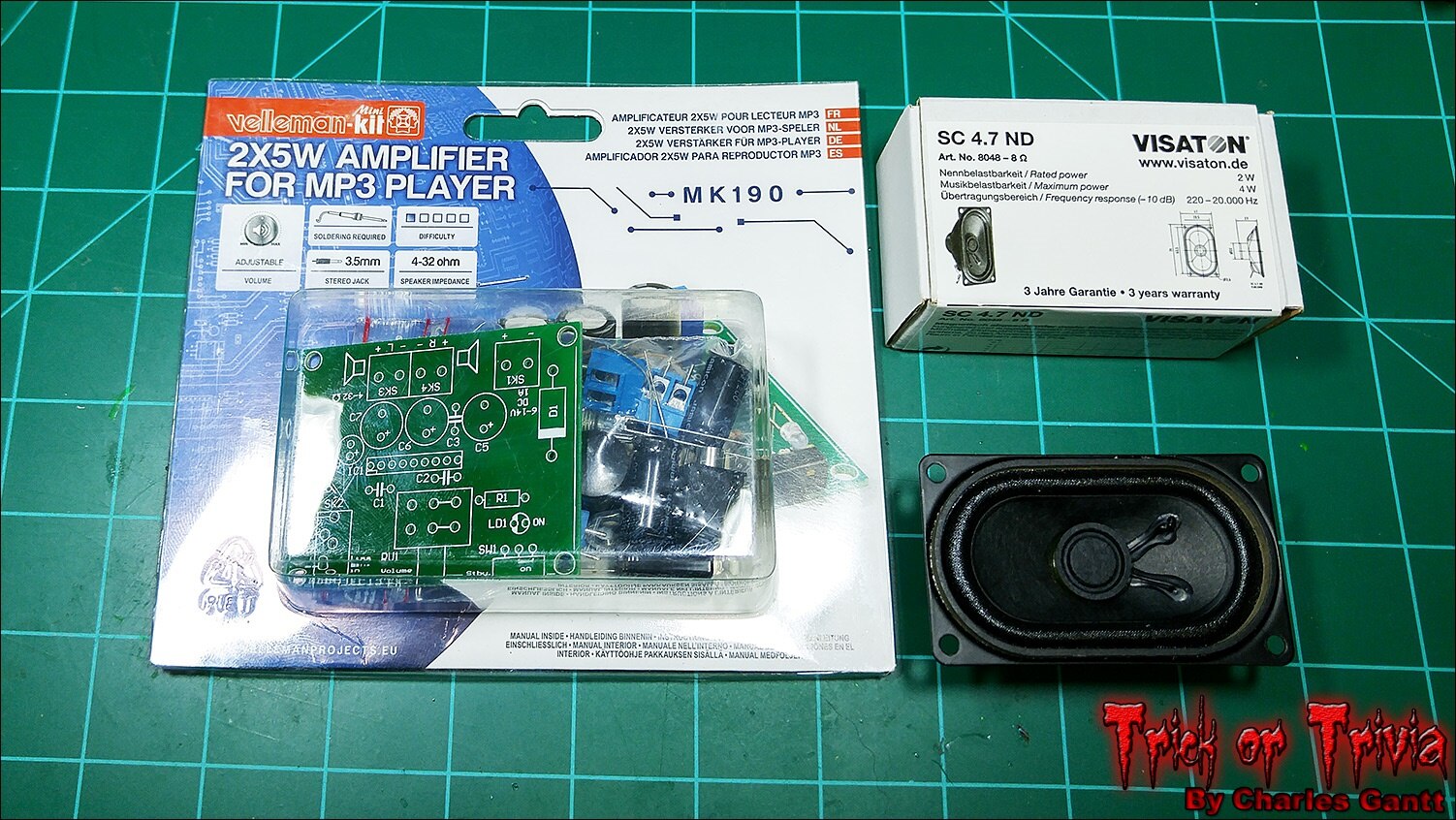
For this project, I chose the Velleman 2x5W Amplifier kit from MCM Electronics. This kit is designed for even the most novice maker to be able to assemble, and it’s quite powerful for its small size. I also chose to use a single small three-inch, eight-Ohm speaker from Visatoneight-Ohm speaker from Visaton. This speakers is a little undersized for this project and this amp, but it works just fine as long as you do not max out the amp’s volume control.
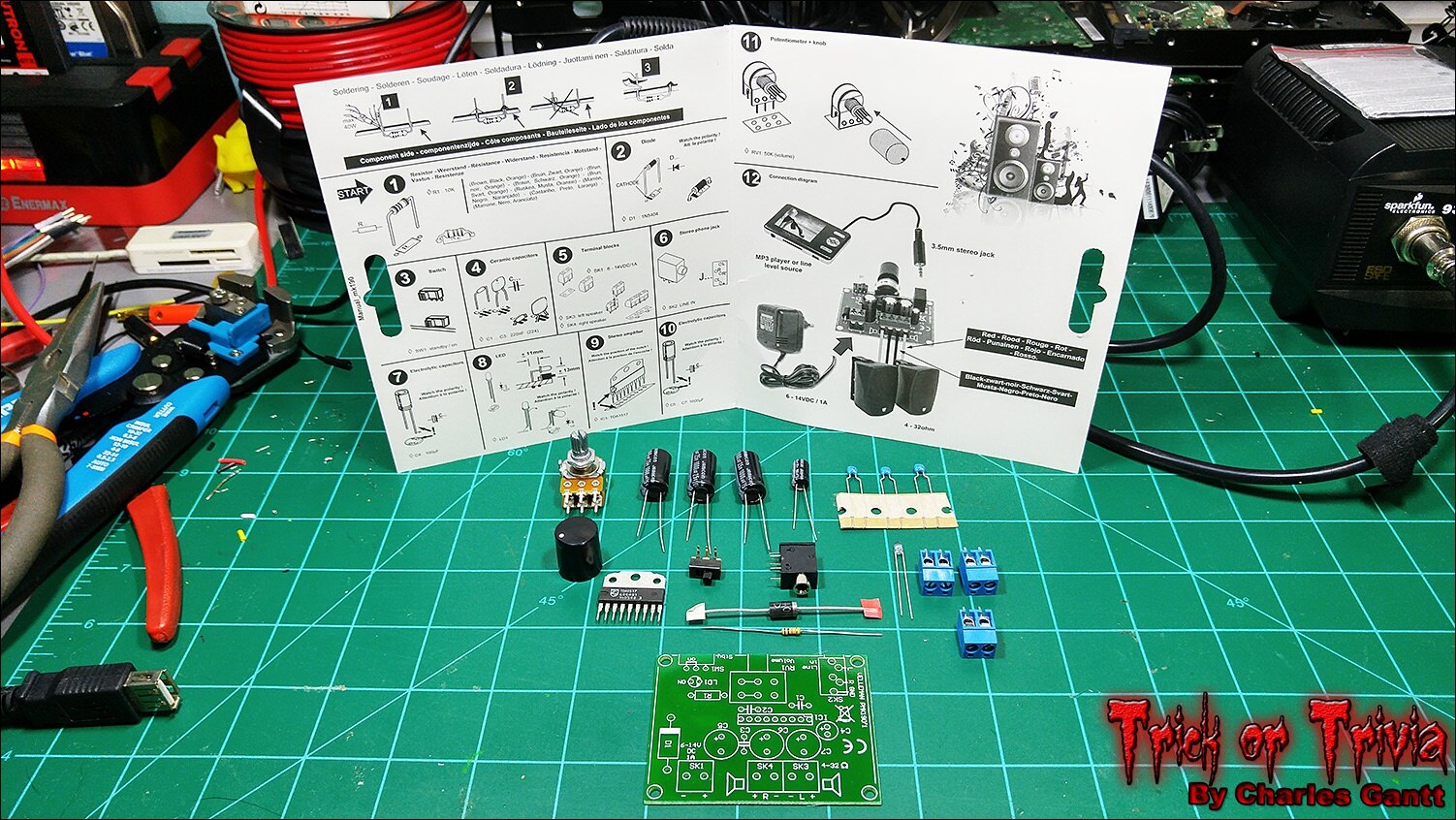
The kit is very straight forward, does not include any confusing, hard-to-identify parts, nor does it utilize any SMD parts that would make it hard to solder. The toughest part to solder in the whole kit is the power indicator LED, as you need to bend it at a very specific point if you want to follow the build instructions 100% word-for-word. I built this entire board in less than 10 minutes.
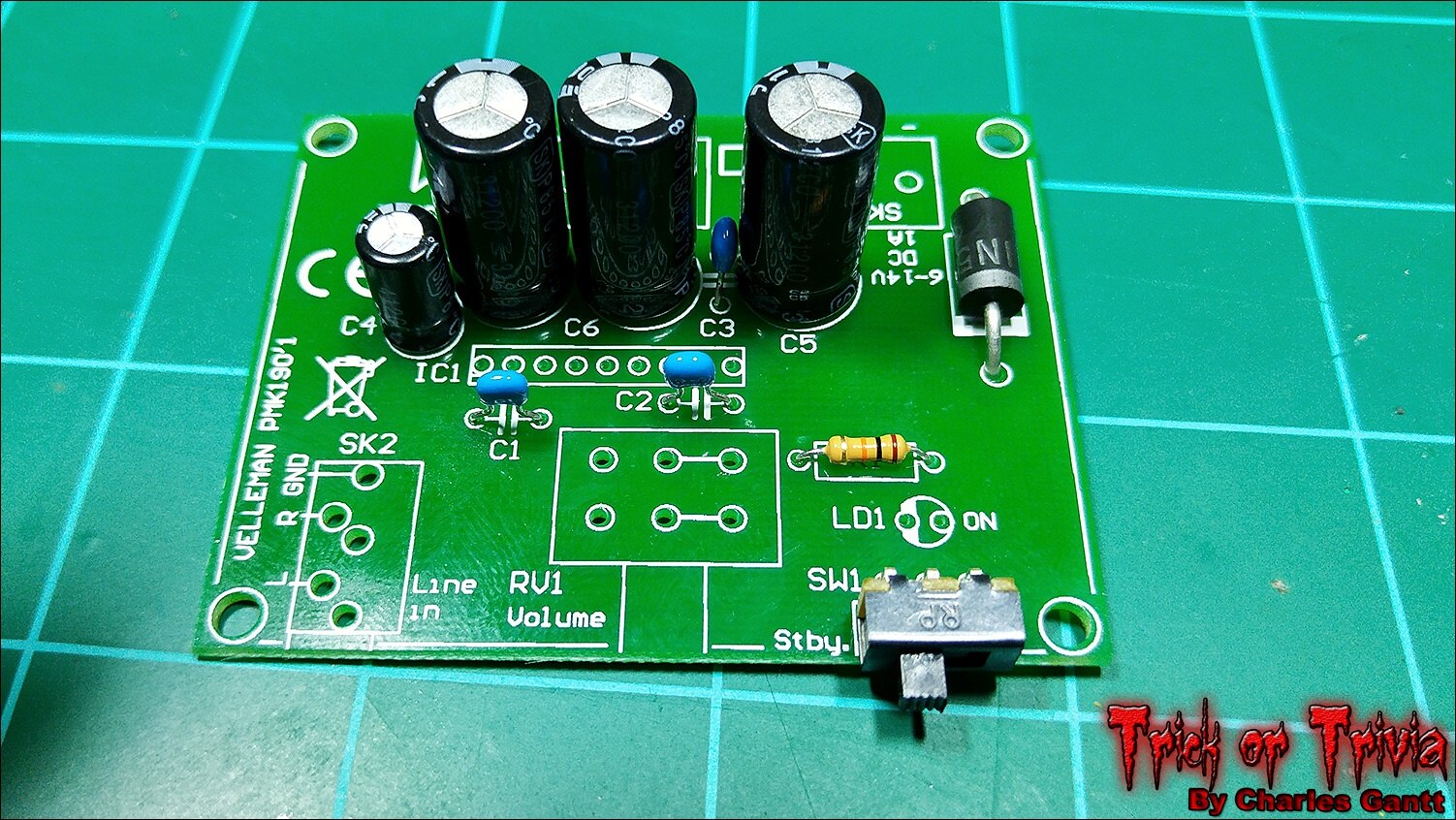
I sort of went off script and soldered up several of the amp’s components at once. If you follow the directions, you will solder each type of component step by step. This was way to slow for me, and I have hand soldered so many SMD boards in the past few months, that I can solder a through-hole board like this with my eyes closed.
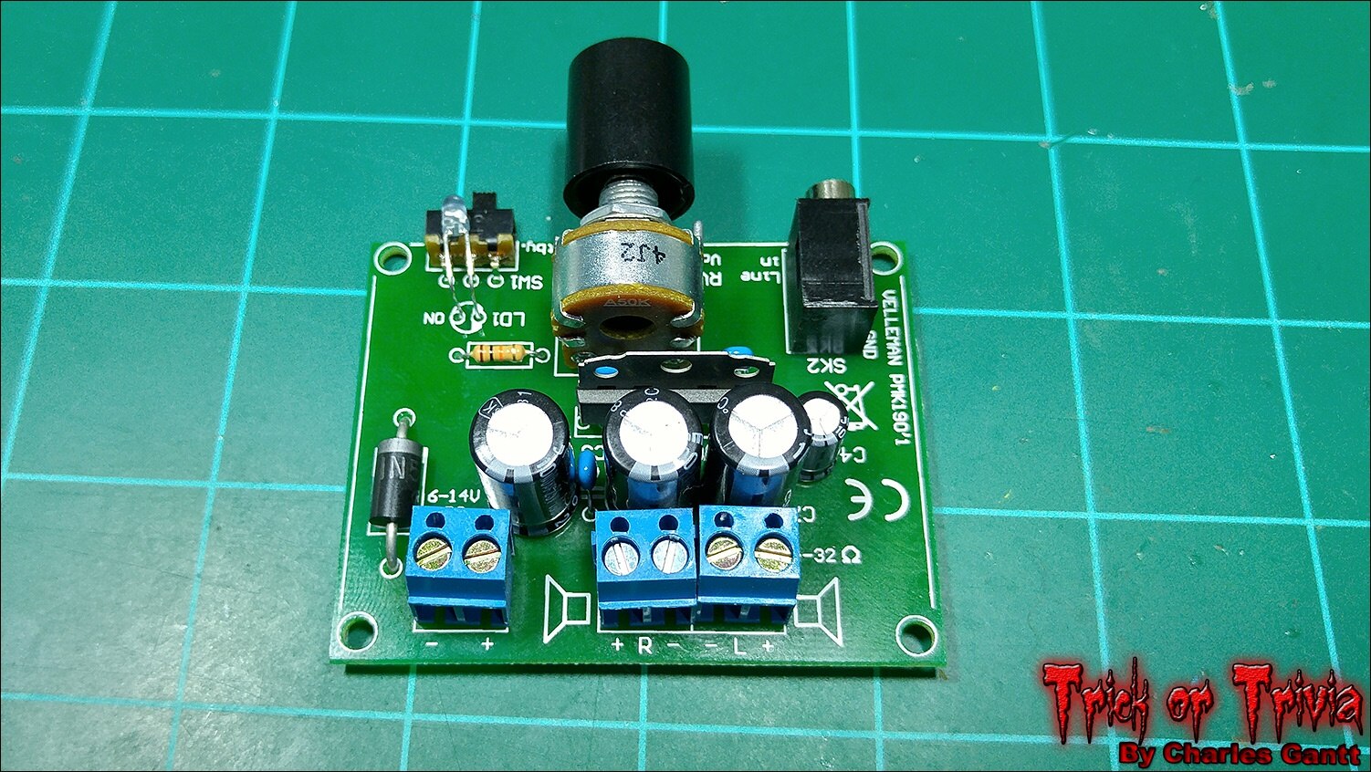
I finished up the board with a second round of soldering. This time I soldered the IC, and other large / heavy components. When soldering terminal blocks, ICs, and other components that are hard to keep in place, or that have several leads, I like to solder one of the leads on an end of the component first. This lets me lock the component in place, then I can use my fingers to re-align the part while re-heating that single solder joint.
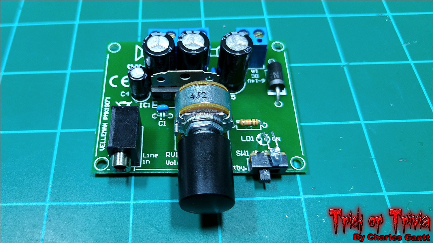
It’s hard to see in this photo, but I set the potentiometer all the way to the left, then placed the knob on it with the indicator dot down in the bottom left corner. This will place the dot almost perfectly opposite this position when the volume is turned to max.
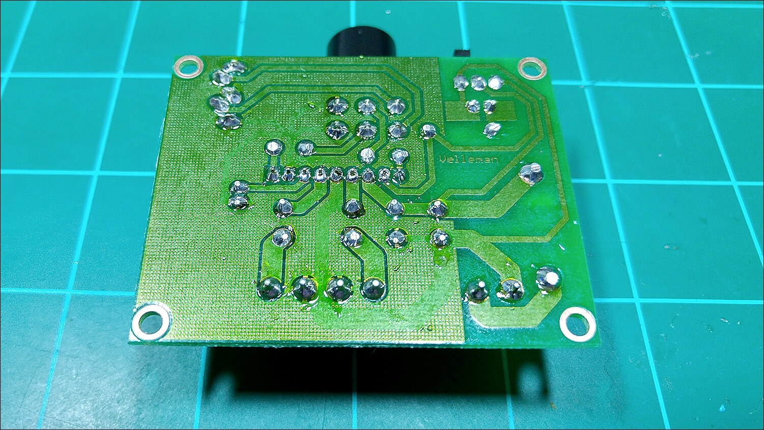
The one thing I always say about soldering is that flux is your friend. Velleman must know this as well because they coated the entire bottom of the PCB in a very sticky resin-based flux. I still used my flux pen on a per-joint basis as I like flux on the component leads I am soldering as well.
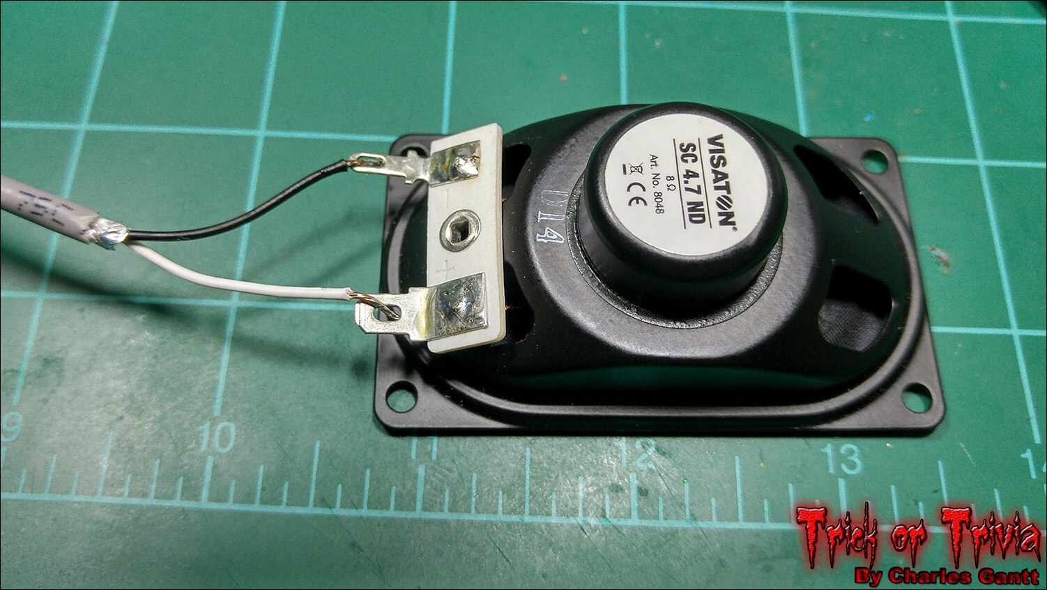
Wiring up the speaker is pretty straight forward as Visaton was kind enough to mark the leads with + and - symbols to identify its leads. For those wondering, the + lead is almost always the larger of the two leads. Rumor has it, that this was adopted as common practice first in the automotive industry back in the 1970s. You will note that I used some spare two-conductor, shielded microphone wire. You can use any two-conductor wire you have, just pay attention to the polarity. The speaker will work even if it’s reversed, but the best sound quality comes from a properly wired speaker.
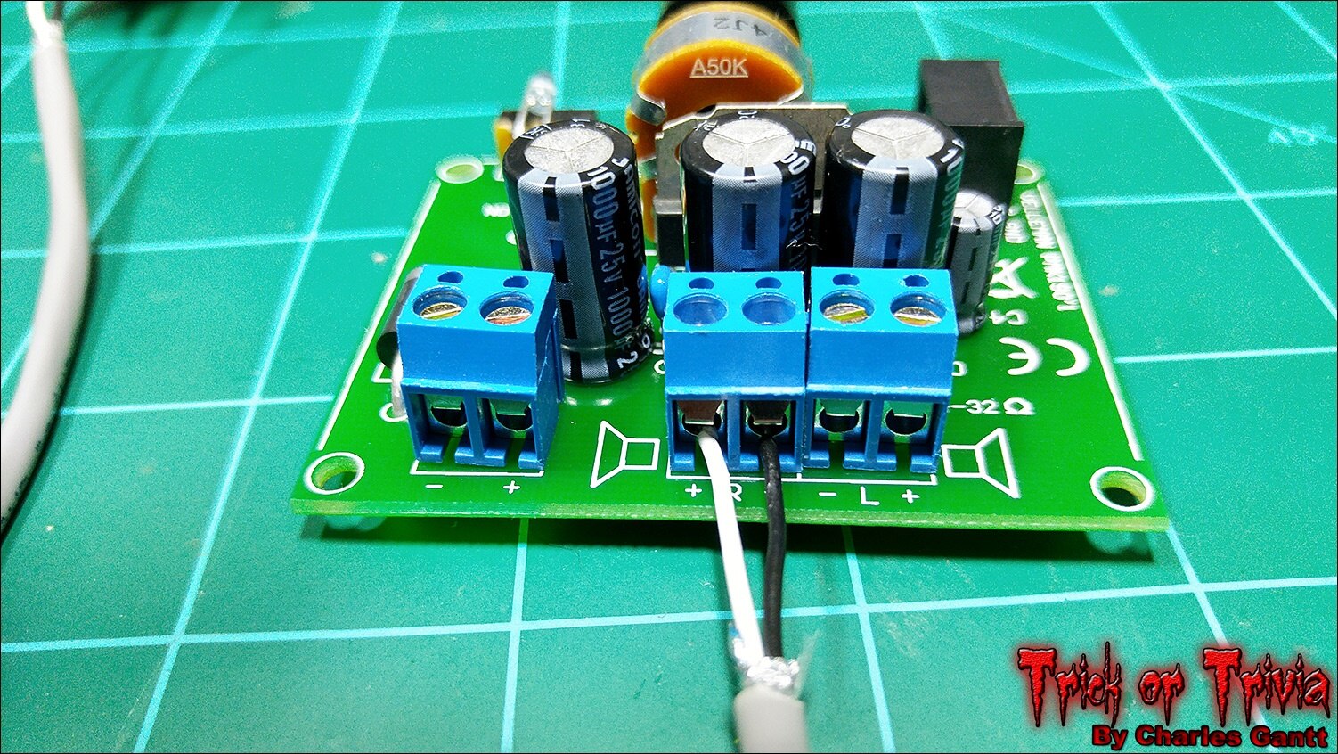
Connect the other end of the speaker wire to the amp while paying attention to the polarity. You can also connect the power cable to the screw terminals to the left at this point. The amp requires a 6-14v 1A DC power source. You can power this with an old 9v or 12v wall-adapter, or even a 9-volt battery, but the battery will struggle to output enough current to keep the amp at full capacty.
The Ambient Audio Code
To start off let's quickly cover the background / ambient audio working and how I set it up to begin when the Raspberry Pi Boots. Below is the Python script that I wrote to play the mp3 file I selected as the ambient source. I have broken out each section, and commented on what it does.
To get started we need to import the pygame library. I know a lot of you would have liked to see me use OMXplayer, but there were some things I could not get to work as they should, and I just chose to use something I was familiar with instead.
import pygame
Next we need to define the path to the ambient.mp3 file, and give it a name.
audio_path = '/home/pi/Desktop/audio/ambient.mp3'
Now we need to set a variable to True
var = True
Now we need to write a while-loop to play our mp3 file, and set it to only play if var is equal to True.
while var ==True:
Now we need to initialize PyGame.
pygame.mixer.init()
Then we need to load the MP3 file we want to play.
pygame.mixer.music.load(audio_path)
Now we need to set the pygame player’s volume. The range is between 0.0 and 1.0 so a setting of 0.5 would be half way.
pygame.mixer.music.set_volume(1.0)
Finally we need to tell pygame to play the MP3 file, and set it to loop five times.
pygame.mixer.music.play(5)
The full code is pasted below. Alternatively you can download this code used in this tutorial at the Github repository for this project. The audio files are available for download from here. If you do not want to modify the code, create a folder in the Desktop directory called “audio” and move all three of the mp3 files into it.
import pygame

audio_path = '/home/pi/Desktop/audio/ambient.mp3'

var = True

while var ==True:
    pygame.mixer.init()
    pygame.mixer.music.load(audio_path)
    pygame.mixer.music.set_volume(1.0)
    pygame.mixer.music.play(5)
Navigate to the Open a new file called ambient.py using the Nano text editor by entering the following command
sudo nano ambient.py
Then copy and paste the code above into the file. Save and exit, and then use the following command to test the pi.
sudo python ambient.py
You should hear the ambient.mp3 file begin to play if you have the amplifier / speaker combo we just built hooked up via a 3.5mm to 3.5mm audio cable from the amp to the Raspberry Pi. To get this python script to run on boot, we need to add it to the Raspberry Pi’s crontab. Enter the following command in the terminal to create a new crontab entry.
sudo crontab -e
Now paste the following line at the bottom of the crontab.
@reboot sudo python /home/pi/Desktop/TriviaScrips/ambient.py
then save and exit out of the file. Reboot the Raspberry Pi using the command below. When the Pi reboots, you should hear the ambient.py file playing after you login.
sudo reboot
If the audio is quite low despite the amplifier’s volume being maxed out, you will need to turn the Raspberry Pi’s volume up. This is as simple as entering the small command found below, into the terminal.
amixer cset numid=1 -- 400
The range of amixer’s volume is -10200 and +400 in centi-dB units. Since we are using an external amplifier, we can set the Raspberry Pi’s volume to its max setting at +400, and adjust the volume on the amp accordingly.
Correct and Incorrect Answer Audio
I plan on changing out the audio files used for the correct and incorrect answer triggers, but for now the two that are in the download will work just fine. I wish I had time to get the Correct and Incorrect audio recorded and mastered, but I have not had time to sit down and hook up my recording gear.
The first thing we need to do is open the TrickorTrivia.py script and make some modifications. This script is the same as the one we used in the last installment of this tutorial, but has a new name. With that said, I am not going to go over every single line of code. Just the few bits and pieces we need to add.
The first thing we need to do is import the pygame library.
import pygame
Now we need to define two audio paths and give them names.
correct_audio_path = '/home/pi/Desktop/audio/correct.mp3'
incorrect_audio_path = '/home/pi/Desktop/audio/incorrect.mp3'
Finally we need to edit the blink_led functions, to make the LED illuminate once when the correct and incorrect answers are selected. We also need to add in a few lines to play the correct and incorrect answer audio files. For a more precise breakdown of this audio code, see the ambient code written earlier in this post.
def blink_led():
    # endless loop, on/off for 1 second
    while True:
        GPIO.output(26,True)
        pygame.mixer.init()
        pygame.mixer.music.load(correct_audio_path)
        pygame.mixer.music.set_volume(1.0)
        pygame.mixer.music.play(5)
        time.sleep(10)
        GPIO.output(26,False)
        GPIO.cleanup()
        pygame.quit()
        sys.exit()
def blink_led_2():
    # endless loop, on/off for 1 second
    while True:
        GPIO.output(19, True)
        pygame.mixer.init()
        pygame.mixer.music.load(incorrect_audio_path)
        pygame.mixer.music.set_volume(1.0)
        pygame.mixer.music.play(5)
        time.sleep(10)
        GPIO.output(19,False)
        GPIO.cleanup()
        pygame.quit()
        sys.exit()
That’s all that we have to modify in this script to get the audio files playing when a button is pressed. When the correct answer is chosen, the green LED will illuminate, the correct.mp3 file will play, and when done, the LED will turn off and the script will exit. The same goes for the incorrect answer. The red LED will illuminate, the incorrect.mp3 file will play, and then when finished the LED will turn off and the script will exit. Below is the full code.
To test if the code works, enter the Desktop GUI by typing the following command:
startx
Then open LXterminal, and navigate to the TrickorTrivia.py script.
cd /home/pi/Desktop/TriviaScrips
Then run the TrickorTrivia.py scrip with the following command:
sudo python TrickorTrivia.py
This should open the trivia interface and when you select the answer, the corresponding LED should light up and audio file play.
I really wish I could have gotten the ambient audio working on a sub-process, but it will work just fine the way I set it up by running on boot via crontab. I will admit that the speaker is a little underpowered, and I am not utilizing the Amp to its full potential. This is an easy fix, if you have an old set of small bookshelf speakers laying around. That is going to wrap this installment of Project: Trick or Trivia. Check back in a few days for the next installment. Until then, remember to Hack The World, and Make Awesome!
Project Introduction
Building The Trivia Interface
- Interfacing Ambient and Triggered Audio Events
- Building The Candy Dispenser & Servo Coding
- Carve Foam Tombstone
- October 24th - Assembly and Testing
- October 28th - Project Wrap-up
Originally published by Charles Gantt on Element14 Community
Part 4: Trick or Trivia Halloween Candy Dispenser #004 - Building The Candy Dispenser & Servo Coding

Welcome back to the Trick or Trivia Blog. In this installment, I am going to cover the candy dispensing mechanical assembly, as well as the coding to get the servo up and running on the Raspberry Pi 2. Up until now, all of the parts needed to build this project were able to be purchased from Newark.com or MCM Electronics, but this portion will require a 3D printer or some handy inguinuity and minor skills with wood working equipment. I have included both the printable .STL files as well as the sketchup design files so that anyone following along at home can recreate, improve, or modify things to fit their needs.
When I came up with the concept of the Trick or Trivia candy dispenser, I spent hours trying to figure out the best way to autonomously dispense Halloween candy one piece at a time, and mocked up a few designs in sketchup. After a lot of thought, I came to the conclusion that the candy needed to be very compact and pretty uniform and consistent in size. It was also important that the candy be very tightly wrapped as loose packaging caused jams. I finally settled on Starburst candies as they fit all of the requirements. Starburst were actually my second choice, with Now & Later candies being my first. Unfortunately I could not find any of them locally, and know that Starburst are found throughout the US and abroad. Let’s get into the meat of things, and talk about the hardware needed for this project.
The Hardware
Below you will see a list of the hardware used to build out the candy dispenser portion of this project. In addition to these components, you will need the following tools: a soldering iron, solder, flush cutters, wire strippers, 12-inches or more of 3-conductor wire, 16 Gauge Galvanized Steel Wire (found at hobby stores), and a bag of Starburst candies.
Newark.com
Newark Part No. | Notes | Qty | Manufacturer / Description |
38Y646738Y6467 | RPi | 1 | RASPBERRY PI 2, MODEL B, |
38Y647038Y6470 | SD Card | 1 | RASPBERRY PI 8GB NOOBS MICRO SD CARD |
44W493244W4932 | PSU | 1 | POWER SUPPLY 5V, 1A |
06W104906W1049 | USB Cable | 1 | USB A PLUG TO MICRO USB B PLUG |
53W628553W6285 | WiFi Dongle | 1 | ADAFRUIT USB WIFI MODULE |
58K382758K3827 | Resistors | 1 | METAL FILM RESISTOR, 220 OHM, 250mW, 1% |
10M846410M8464 | General Purpose Diode | 1 | 1N40011N4001 Rectifier Diode 50 V 1 A |
34C109234C1092 | PSU Vreg | 1 | 7805 LINEAR VOLTAGE REGULATOR, 5V, TO-220-3 |
17F216517F2165 | PSU Filter Cap | 1 | CERAMIC CAPACITOR 0.1UF, 50V, X7R, 20% |
69K790769K7907 | PSU Filter Cap | 1 | ELECTROLYTIC CAPACITOR 100UF, 50V, 20%, |
14N941814N9418 | PSU LED | 1 | RED, T-1 3/4 (5MM) |
| 49Y171249Y1712 | 7-Inch Touch Screen | 1 | Raspberry Pi 7" Touch Screen Display |
| 66H746266H7462 | Strip Board | 1 | VECTOR ELECTRONICS-8022-PCB, Tracks(Strip Board) |
| 21M490921M4909 | Screw Terminal | 2 | MOLEX-39543-0002-TERMINAL BLOCK |
MCM Electronics
MCM Part No. | Notes | Qty | Manufacturer / Description |
Servo | 1 | Micro Servo |
3D Printing The Candy Dispenser Assembly
I chose to 3D print the parts for the candy dispenser simply because I have a few 3D Printers at my disposal at home, and could quickly design everything in Sketchup. If you do not have a 3D printer, you could easily build this assembly from wood or even foam core. The most important thing to remember is to leave enough clearance on all moving parts to negate any candy size anomalies.
Download all of the .STL files and the Sketchup design file from Thingiverse.com.
To keep this blog at a somewhat reasonable length, I am not going to post any images of the parts being 3D printed but as you can see from the image below, they print well at a 0.25mm layer height. I used Voltivo Excelfil PLA Filament as the printing medium as PLA is more food-safe than ABS. Since the candy is wrapped in wax-coated paper, PLA is fine to make the dispenser out of.

I mocked up the candy dispenser on a scrap box from a previous Newark order, and used hot glue to temporarily stick everything together. This was a very important step as I realized that the plunger tube was about 2mm taller than the magazine was despite being exactly the same in the sketchup file. I printed the tube again and the second try was perfect. I suspect a slicing error to be the cause of the first tubes difference. I apologize for the low-quality image, I simply got so wrapped up in getting this to work, that I forgot to take one, and had to use a screen cap from a video of everything working.
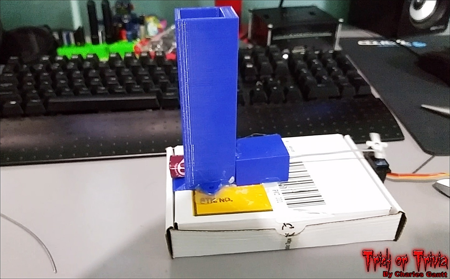
In the image above you can see that I have the servo mounted to the back of the box, with the push-rod made from the 16 gauge wire pushing the plunger into the tube. It took a little trial and error to get the length right, and to get the servo’s horn placed just right, so that it would push candy out and not bind on the return stroke.
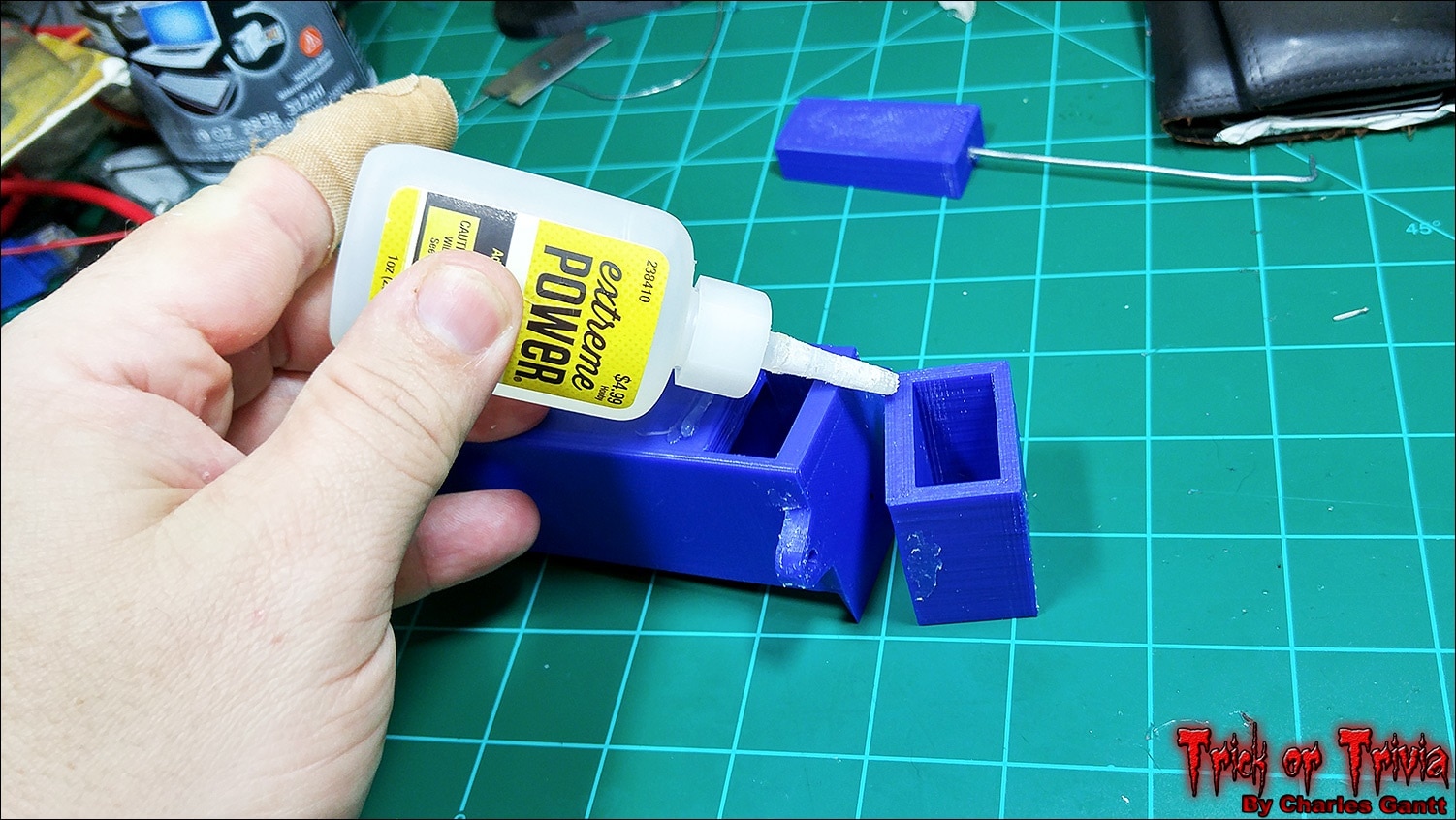
With everything lined up and secure, I tested the dispenser for over an hour until I was confident that everything would work fine. I then super glued the plunger tube to the candy magazine using a thick, gel-like super glue. If this were ABS plastic I would have solvent-welded it together using acetone instead.
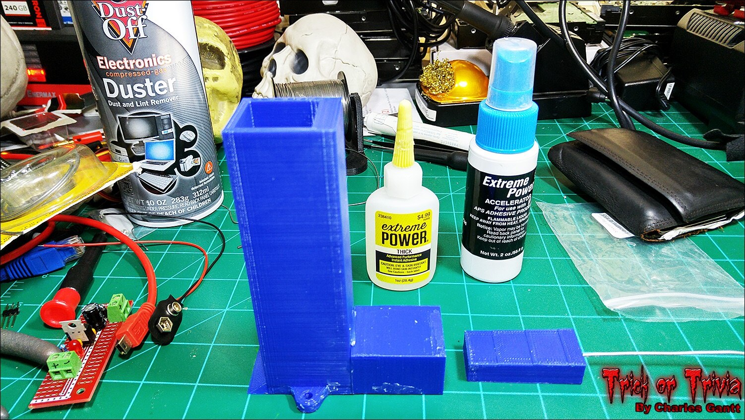
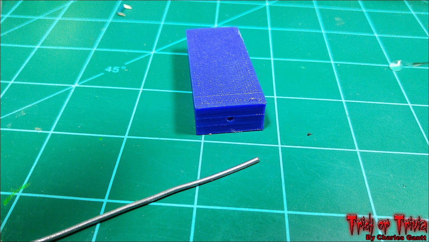
I then glued the steel rod into the plunger block using hot glue. I chose hot glue as it is easier to remove if I need to change its length.
With the easy part done, it was time to move on to getting the code for the servo working.
Wiring and Coding the Servo.
When designing the original kit for this project I listed a normal-sized hobby servo as I thought it’s extra power would be needed, but as it turns out, a smaller 9g servo works much better. This is due to the fact that the candy sometimes binds in the tube if it’s wrapper is coming loose, and when it binds, the bigger servo will actually bend the steel push rod. The 9g servo simply stalls out, preventing the rod from bending.
The servo I am using is a small 9g metal-gear servo from Hobby King’s Turnigy line, but the one listed in the parts list at the top of this post will work just as good. I also had issues trying to drive the original Tower Pro servo from the Raspberry Pi 2, even with a 6-volt, 5-amp power supply hooked to it. The smaller 9G servos worked just fine with the 5V power supply we will build later in this post.
The PIGPIO Library
To drive the servo and retain audio output I chose to install the pigpio library. Installing it is as easy as entering the following commands into the terminal one by one.
wget abyz.co.uk/rpi/pigpio/pigpio.zip
unzip pigpio.zip
cd PIGPIO
make
sudo make install
Then restart the Raspberry Pi with the following command.
sudo reboot
Once the Pi is back up and running, we need to start the pigpio module using the following command.
sudo pigpiod
This command will need to be ran every time the Raspberry Pi reboots. I simply added it to the crontab, just like we did with the command that plays the ambient audio on boot. In the event you need to stop the pigpio module, simply run the commands below. To find out more about what the pigpio module can do, check out its info-page.
sudo killall pigpiod
Servo Control Code
I chose the pigpio module because it not only allows the user to utilize all of the Raspberry Pi’s GPIO pins as PWM pins, but because it does not block audio like some of the other servo control solutions do. An added bonus is how easy it is to program servo control using Python with this library. Below is a breakdown of the servo code, followed by the full TrickOrTrivia code with the servo control integrated. As always, you can find the full code for this project at its Github repo.
First we need to import the time and pigpio libraries.
import time
import pigpio
Next we need to define which GPIO pin is connected to the servo.
servos = 4 #GPIO number
Now we need to initialize the pigpio library
pi = pigpio.pi()
This next block of code is the function that makes the candy dispenser’s plunger move back and forth to dispense three pieces of candy upon a correct answer. We are telling the servo to move hard right with a pulsewidth of 2500, and then move a little more than 90 degrees left with a pulsewidth of 1300. We wait 0.5 seconds between each move. When finished, we turn the servo off by setting a pulse width of 0, and telling the pigpio module to stop. Finally we break out of this function.
def correct_servo ():
        while True:
            pi.set_servo_pulsewidth(servos, 2500)
            time.sleep(.5)


            pi.set_servo_pulsewidth(servos, 1300)
            time.sleep(.5)


            pi.set_servo_pulsewidth(servos, 2500)
            time.sleep(.5)


            pi.set_servo_pulsewidth(servos, 1300)
            time.sleep(.5)


            pi.set_servo_pulsewidth(servos, 2500)
            time.sleep(.5)


            pi.set_servo_pulsewidth(servos, 1300)
            time.sleep(.5)


            pi.set_servo_pulsewidth(servos, 0);
            pi.stop()
            break
The same code works for the incorrect answer, but only dispenses a single piece of candy.
def incorrect_servo ():
    while True:
        pi.set_servo_pulsewidth(servos, 2500)
        time.sleep(.5)


        pi.set_servo_pulsewidth(servos, 1300)
        time.sleep(.5)


        pi.set_servo_pulsewidth(servos, 0);
        pi.stop()
        break
In the full code below, you will see that I call each of these functions in the Blink_LED functions.
from Tkinter import *
import RPi.GPIO as GPIO
import time
import sys
import pygame
import pigpio

GPIO.setwarnings(False)
GPIO.setmode(GPIO.BCM)
GPIO.setup(26, GPIO.OUT)
GPIO.setup(19, GPIO.OUT)

servos = 4 #GPIO number
pi = pigpio.pi()

state = True

correct_audio_path = '/home/pi/Desktop/audio/correct.mp3'
incorrect_audio_path = '/home/pi/Desktop/audio/incorrect.mp3'

def correct_servo ():
        while True:
            pi.set_servo_pulsewidth(servos, 2500)
            time.sleep(.5)
            pi.set_servo_pulsewidth(servos, 1300)
            time.sleep(.5)
            pi.set_servo_pulsewidth(servos, 2500)
            time.sleep(.5)
            pi.set_servo_pulsewidth(servos, 1300)
            time.sleep(.5)
            pi.set_servo_pulsewidth(servos, 2500)
            time.sleep(.5)
            pi.set_servo_pulsewidth(servos, 1300)
            time.sleep(.5)
            pi.set_servo_pulsewidth(servos, 0);
            pi.stop()
            break

def incorrect_servo ():
    while True:
        pi.set_servo_pulsewidth(servos, 2500)
        time.sleep(.5)
        pi.set_servo_pulsewidth(servos, 1300)
        time.sleep(.5)
        pi.set_servo_pulsewidth(servos, 0);
        pi.stop()
        break

def blink_led():
    # endless loop, on/off for 1 second
    while True:
        GPIO.output(26,True)
        pygame.mixer.init()
        pygame.mixer.music.load(correct_audio_path)
        pygame.mixer.music.set_volume(1.0)
        pygame.mixer.music.play(5)
        time.sleep(10)
        correct_servo()
        GPIO.output(26,False)
        GPIO.cleanup()
        pygame.quit()
        sys.exit()

def blink_led_2():
    # endless loop, on/off for 1 second
    while True:
        GPIO.output(19, True)
        pygame.mixer.init()
        pygame.mixer.music.load(incorrect_audio_path)
        pygame.mixer.music.set_volume(1.0)
        pygame.mixer.music.play(5)
        time.sleep(10)
        incorrect_servo()
        GPIO.output(19,False)
        GPIO.cleanup()
        pygame.quit()
        sys.exit()

root = Tk()
root.overrideredirect(True)
root.geometry("{0}x{1}+0+0".format(root.winfo_screenwidth(), root.winfo_screenheight()))
root.focus_set()  # <-- move focus to this widget
root.configure(background='black')

label_1 = Label(root, text="Welcome to Trick or Trivia", font=("Helvetica", 36), bg="black", fg="white")
label_1.grid(columnspan=6,padx=(100, 10))
label_2 = Label(root, text="Answer the question for candy!", font=("Helvetica", 28), bg="black", fg="red")
label_2.grid(columnspan=6, pady=5, padx=(100, 10))
label_3 = Label(root, text="Casper is a friendly ____!", font=("Helvetica", 32), bg="black", fg="green")
label_3.grid(columnspan=6, pady=5, padx=(100, 10))
button_1 = Button(root, text="Ghost", font=("Helvetica", 36), command=blink_led)
button_1.grid(row=4, column=2, pady=5, padx=(100, 10))
button_2 = Button(root, text="Ghast", font=("Helvetica", 36), command=blink_led_2)
button_2.grid(row=4, column=4, sticky=W, padx=(100, 10))
button_3 = Button(root, text="Ghoul", font=("Helvetica", 36), command=blink_led_2)
button_3.grid(row=5, column=2, pady=5, padx=(100, 10))
button_4 = Button(root, text="Gremlin", font=("Helvetica", 36), command=blink_led_2)
button_4.grid(row=5, column=4, sticky=W, padx=(100, 10))
label_4 = Label(root, text="Correct Answer = 3 Pieces", font=("Helvetica", 20), bg="black", fg="green")
label_4.grid(columnspan=6, padx=(100, 10))
label_5 = Label(root, text="Incorrect Answer = 1 Piece", font=("Helvetica", 20), bg="black", fg="red")
label_5.grid(columnspan=6, padx=(100, 10))

root.mainloop()
Building a 5V Regulated Power Supply
The 9g servo we are using requires a 5V power source, and while the Raspberry Pi is capable of powering it for free movement, the servo could pull 2-3 amps if it binds up. The Pi is not capable of sourcing this much current through its GPIO, and it could cause damage to the Pi. So we are going to build a quick and simple regulated 5V power supply. This power supply will not supply 2-3 amps, but can sustain 1-amp without a heatsink.
To build this PSU you will need the following components, as well as a soldering iron, flush cutters, and a 12-30V DC power source.
58K382758K3827 | Resistors | 1 | METAL FILM RESISTOR, 220 OHM, 250mW, 1% |
10M846410M8464 | General Purpose Diode | 1 | 1N40011N4001 Rectifier Diode 50 V 1 A |
34C109234C1092 | PSU Vreg | 1 | 7805 LINEAR VOLTAGE REGULATOR, 5V, TO-220-3 |
17F216517F2165 | PSU Filter Cap | 1 | CERAMIC CAPACITOR 0.1UF, 50V, X7R, 20% |
69K790769K7907 | PSU Filter Cap | 1 | ELECTROLYTIC CAPACITOR 100UF, 50V, 20%, |
14N941814N9418 | PSU LED | 1 | RED, T-1 3/4 (5MM) |
| 49Y171249Y1712 | 7-Inch Touch Screen | 1 | Raspberry Pi 7" Touch Screen Display |
| 66H746266H7462 | Strip Board | 1 | VECTOR ELECTRONICS-8022-PCB, Tracks(Strip Board) |
| 21M490921M4909 | Screw Terminal | 2 | MOLEX-39543-0002-TERMINAL BLOCK |
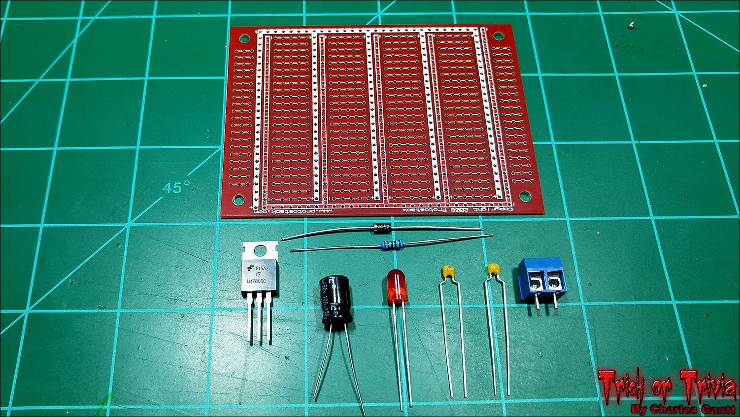
A 5V regulated power supply circuit is quite simple to build thanks to the fairly common LM7805 voltage regulator, and requires just five components to get up and running. A 100uF capacitor, two 0.1pF ceramic capacitors, a 1N004 diode, and the LM7805 regulator. I am adding two screw terminals, and an indicator LED to the mix. I want to design a pcb for this, but for now a piece of protoboard will work just fine.
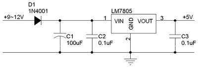
Following the schematic above, build the power supply and solder in each component. The protoboard I am using is different from the one listed above as I have a big supply of these from Protostack.com, so I just used one of mine.
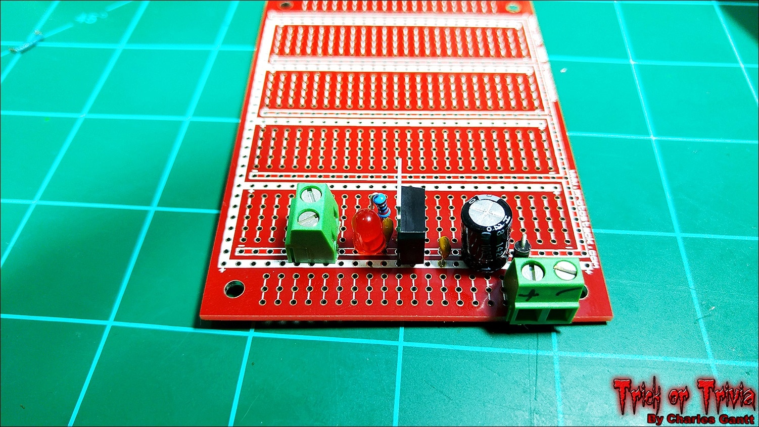
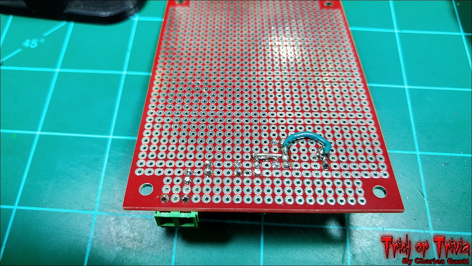
With all of the components soldered together, I made the necessary jumps from each component to the next. I lucked out with the Protostack board as it has integrated power and ground rails. This cut down on the number of jumps I needed to make.
With everything soldered up, I trimmed the board down to reduce its size, and connected a 12v 1amp power source. The red LED lit up and I confirmed 5V out with a multimeter.
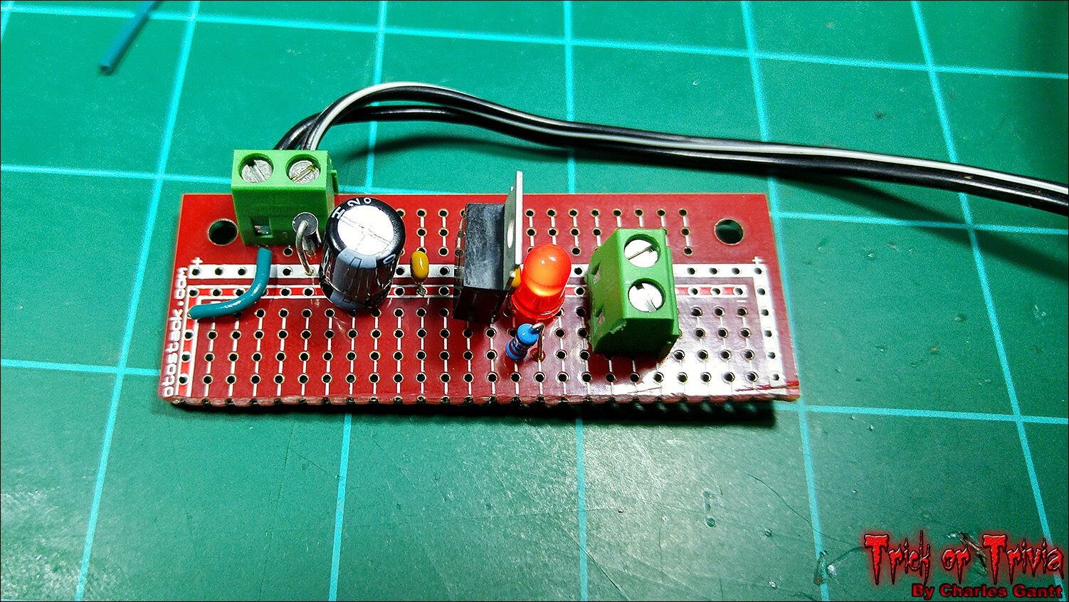
With the power supply built and working, we can move on to testing our servo!
Testing the Servo
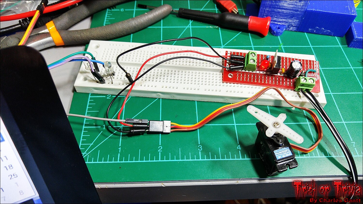
Connect the servo to the power supply as shown. Then connect the servos signal wire to the Raspberry Pi’s GPIO Pin 4 using the BCM schema. You also need to connect the power supply’s ground to the Raspberry Pi’s ground. You can see that I have done that here with the GND rail on a breadboard I am using to power the mock-up’s LEDs.
To test the servo, let’s create a new test script with Python. Using the Nano text editor create a new file within the Trivia Scripts directory using the following commands.
cd /home/pi/Desktop/TriviaScrips
nano servo_test.py
Now paste the following code into the file you just created. Then exit out of the file, saving the changes.
import time
import pigpio
import sys

servos = 4 #GPIO number

pi = pigpio.pi()
#pulsewidth can only set between 500-2500

def correct_servo ():
        while True:
            pi.set_servo_pulsewidth(servos, 2500)
            time.sleep(.5)
            pi.set_servo_pulsewidth(servos, 1300)
            time.sleep(.5)
            pi.set_servo_pulsewidth(servos, 2500)
            time.sleep(.5)
            pi.set_servo_pulsewidth(servos, 1300)
            time.sleep(.5)
            pi.set_servo_pulsewidth(servos, 2500)
            time.sleep(.5)
            pi.set_servo_pulsewidth(servos, 1300)
            time.sleep(.5)
            pi.set_servo_pulsewidth(servos, 0);
            pi.stop()
            break


def incorrect_servo ():
    while True:
        pi.set_servo_pulsewidth(servos, 2500)
        time.sleep(.5)
        pi.set_servo_pulsewidth(servos, 1300)
        time.sleep(.5)
        pi.set_servo_pulsewidth(servos, 0);
        pi.stop()
        break

correct_servo()
incorrect_servo()
sys.exit
To run the script, use the following command.
sudo python servo_test.py
The servo should move back and forth a few times before finishing up, and the script terminating. If it worked, copy the full foginator code that I posted earlier in this post, and edit the foginator2000.py script. Delete the existing code and paste the new code into it. Save and exit. Now you should be able to run the Foginator2000.py script and when you select the correct answer, three pieces of candy will be ejected from the magazine like in the video below.
I apologize for this post being so late, but as you might know, South Carolina got hit by a pretty massive rainstorm over the last few days. That has seriously hindered my ability to work on anything, but we are back to blue skies now. I hope you enjoyed this installment of my Trick or Trivia project, and I hope that you learned a thing or two about the Raspberry Pi and servos. That is going to wrap this installment of Project: Trick or Trivia. Check back in a few days for the next installment. Until then, remember to Hack The World, and Make Awesome!
Project Introduction
Building The Trivia Interface
- Interfacing Ambient and Triggered Audio Events
- Building The Candy Dispenser & Servo Coding
- Carve Foam Tombstone
- October 24th - Assembly and Testing
- October 28th - Project Wrap-up
Originally published by Charles Gantt on Element14 Community
Part 5: Trick or Trivia Halloween Candy Dispenser #005 - Building The Tombstone

Welcome back to the Trick or Trivia Blog. In this installment, I am going to lightly document the process I used to build the faux tombstone that will be used to hold the Raspberry Pi 7-inch touchscreen. My original plan was to buy a 5-foot tall Frankenstein statue, or some other tall halloween figure. Unfortunately I was unable to find anything locally that fit within my budget of $100 for this segment. After talking to a few friends, and watching several videos on YouTube, I decided to just build my tombstone from 1-inch thick construction foam insulation.
During the planning of this project, I realized I needed to make the tombstone thicker than 1-inch as the foam is quite weak. This led me to search for 2-inch thick foam, and while it exist, it seems to not be sold anywhere in South Carolina. In the end, I wish I would have been able to find the 2-inch thick foam as gluing the sheets together proved to take a lot longer than I anticipated. However, the end result was still quite amazing, and I find myself still wondering how I managed to pull off such a realistic looking tombstone.
The Hardware and Tools Needed
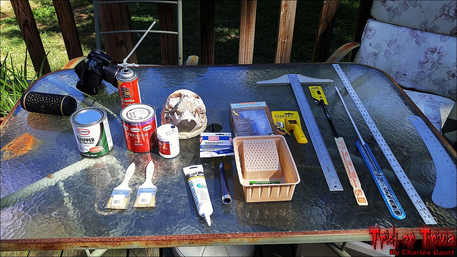
Below you will see a list of the hardware and tools used to build the tombstone that we will use to hold our 7-inch touchscreen. All of these tools and materials can be purchased at your local home improvement store, and most can even be found online. The only thing that is brand specific is the Glidden Gripper primer that is used as a glue. This primer / sealer is what many foam tombstone builders use to glue their models together as it is cheap, dries without exposure to air, and it carves easily.
-
- Glidden Gripper Primer / Sealer (Used as glue to glue the foam together.
- Stone Grey Latex Paint
- Black Latex Paint
- 2oz acrylic craft paint White
- 2oz acrylic craft paint OD Green
- 2oz acrylic craft paint Desert Tan
- Acrylic Caulking
- Great Stuff Foam In A Can
- 1-inch Closed Cell Insulation Foam sheet. 4’x8’
- Xacto / Hobby Knife
- Jigsaw with 2” 32TPI blade or 32TPI Hacksaw blade
- 2x 2-inch Chip Brushes
- Old Soldering Iron or Wood Burning Iron Kit
- Popsicle Sticks or Wooden BBQ Skewers
- 5-inch Prop Skull
- 1-meter straight-edge
- Curve Ruler
- Compass / Circle Ruler
- Fine Point Sharpie
- Acetone / Acetone-based fingernail polish remover
- Hot Glue Gun
- Stanley Sureform Foam Shaping Rasp
The Design

I chose to go with a mix between a traditional tombstone, and something you might find in a classic B-grade horror flick. After quickly scratching out a general outline on a piece of paper, I sat down in Sketchup and modeled what the tombstone would look like. As you can see, it borrows from traditional, gothic, and horror-movie tombstone designs. The overall height is about 5.5-feet, and places the touchscreen at a height that most children can easily access it.
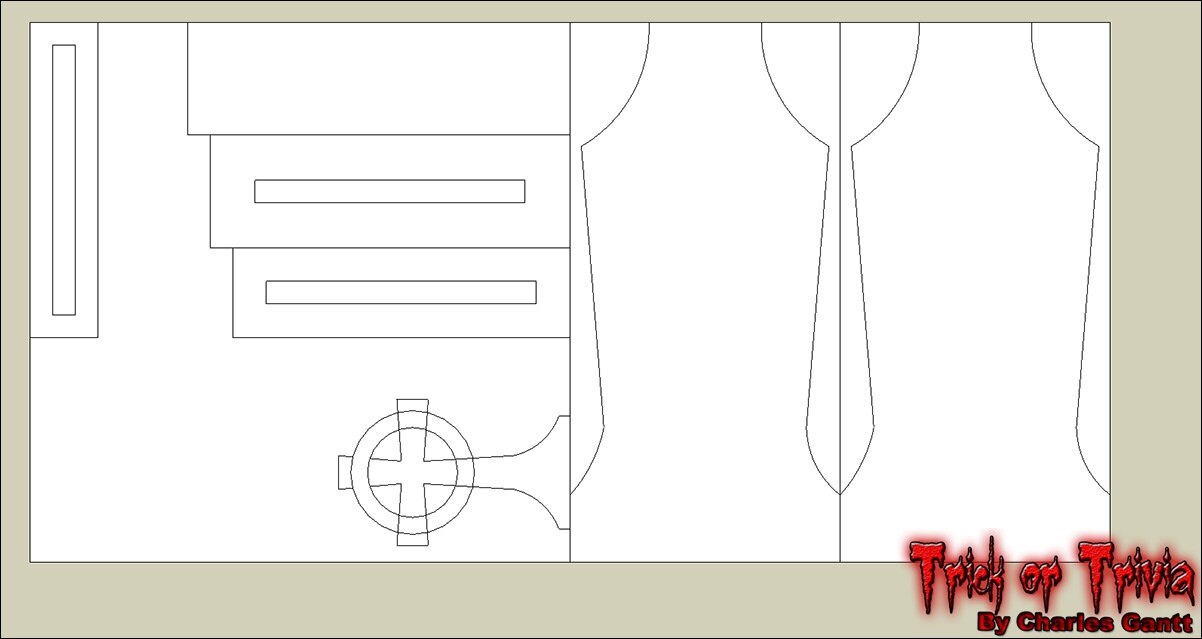
This design fits entirely from one 4’x8’x1” sheet of pink / green / blue insulation foam from any big-box home improvement store. I do suggest gluing the two main tombstone pieces together before hand and cutting them out once they are dry.
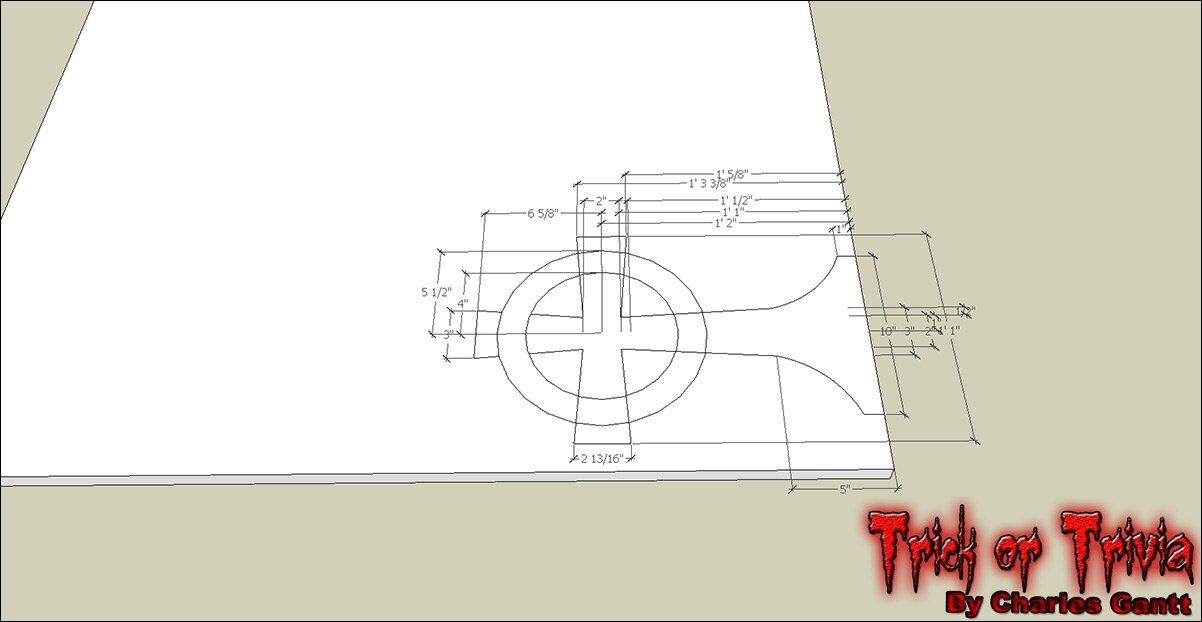
You can download the Sketchup design file for this project which includes 3D models of the finished tombstone, layouts with dimensions, etc, from here. Use this file to get the dimensions you will need for each piece. I simply printed out each design on a normal sheet of paper, and used them to layout each part onto the foam.
The Build
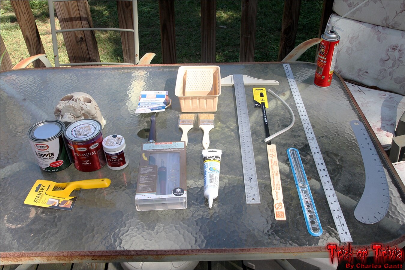
I like to start all of my projects by laying out any tools, components and materials neatly so that I can quickly and easily access them when needed.
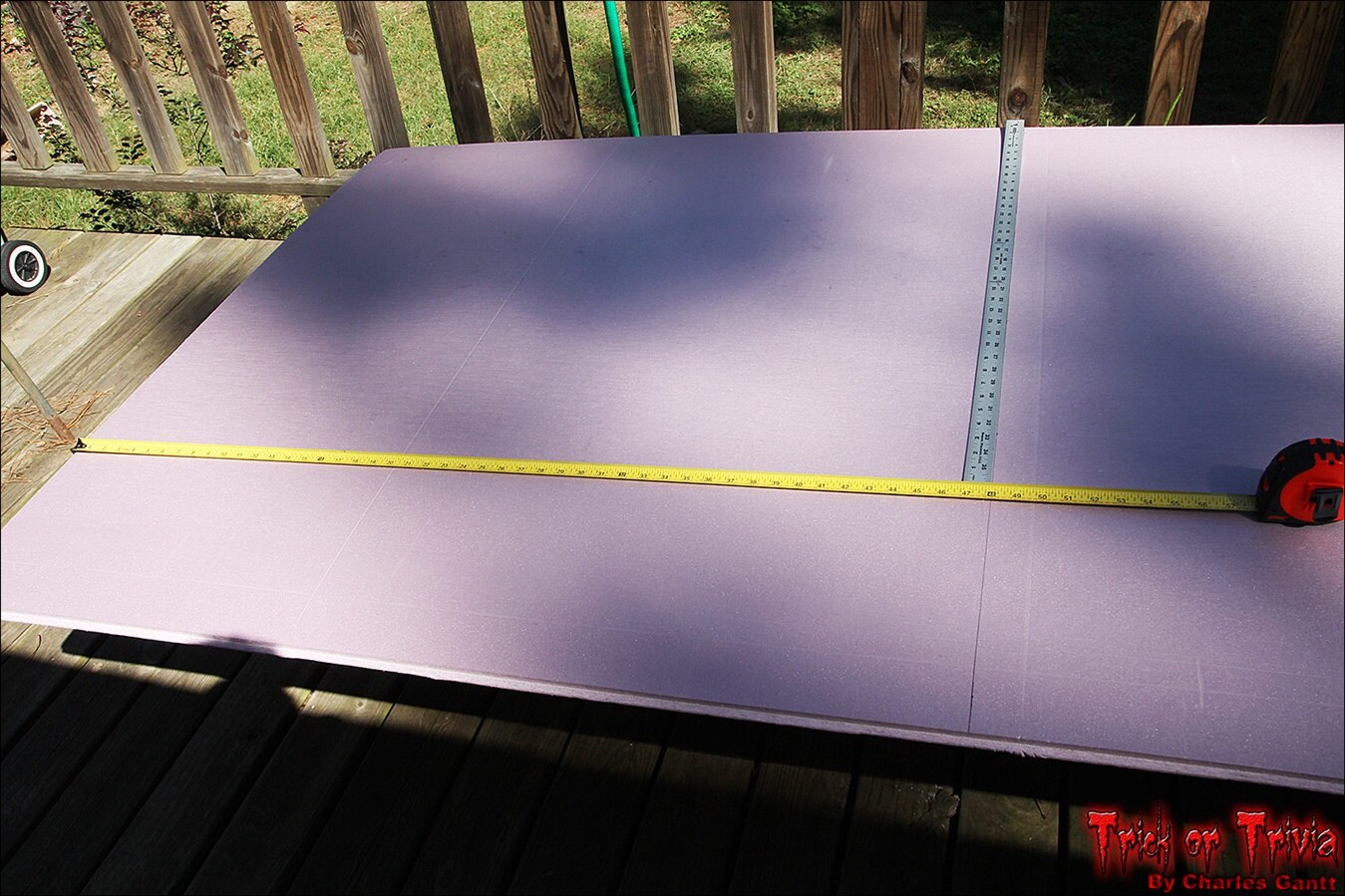
With all of the tools and materials laid out, I decided that the easiest thing to do would be to cut the large foam sheet into halves, and then half one of the halves again. This would give me two 2-foot by 4-foot pieces which I could then glue together and set aside while the glue dries.

I do not have a photo of the actual glue application process as it was fairly warm outside, and the Glidden Gripper was drying almost instantly. The basic method I used is exactly the same as you would use when painting a wall. Use a small roller brush to apply a very liberal coat of the Gripper onto one side of one of the sheets of foam. Then place the other sheet on top of the freshly “painted” surface. Align things so that at least two edges align at a right angle.
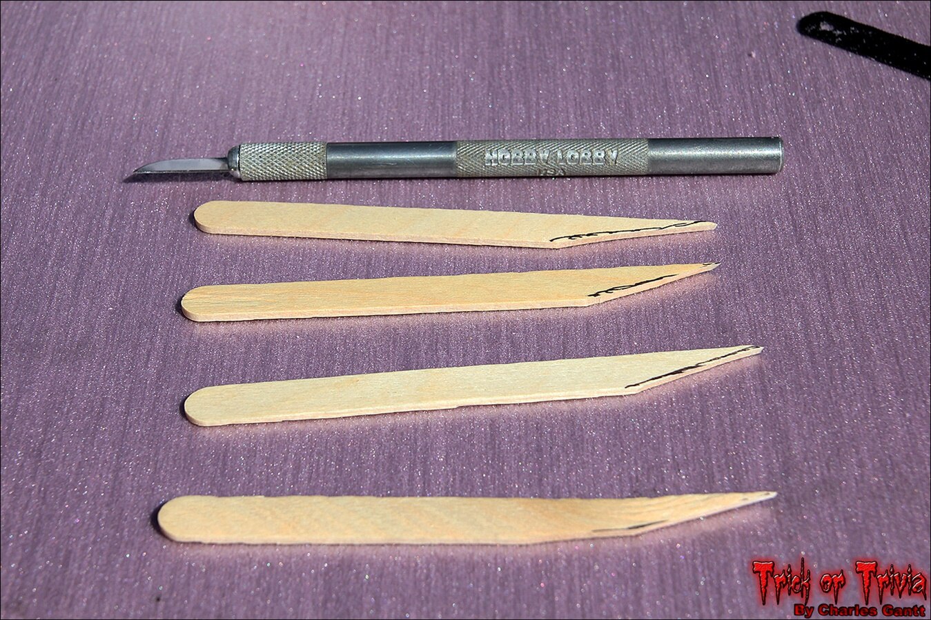
I knew I would need a way to index the two sheets of foam together, and after searching for toothpicks for about half an hour, I found some craft sticks that would work just fine if I cut a point onto them with my hobby knife. Place one of these sticks in each corner of the foam sheets, and push down until you are sure that both layers have been penetrated.
Now set the laminated foam sheets to the side, placing heavy objects on top of them. This will help apply enough pressure so that the sheets get a good bond when the Glidden Gripper dries. I used two drink coolers filled with water, which applied about 200lbs of pressure.

With the two large pieces drying, let’s move onto cutting out the base of the tombstone. We will need to glue it together as well. As I mentioned earlier, I printed out the design files for each element of this build, and I used a yardstick to transfer the dimensions over.
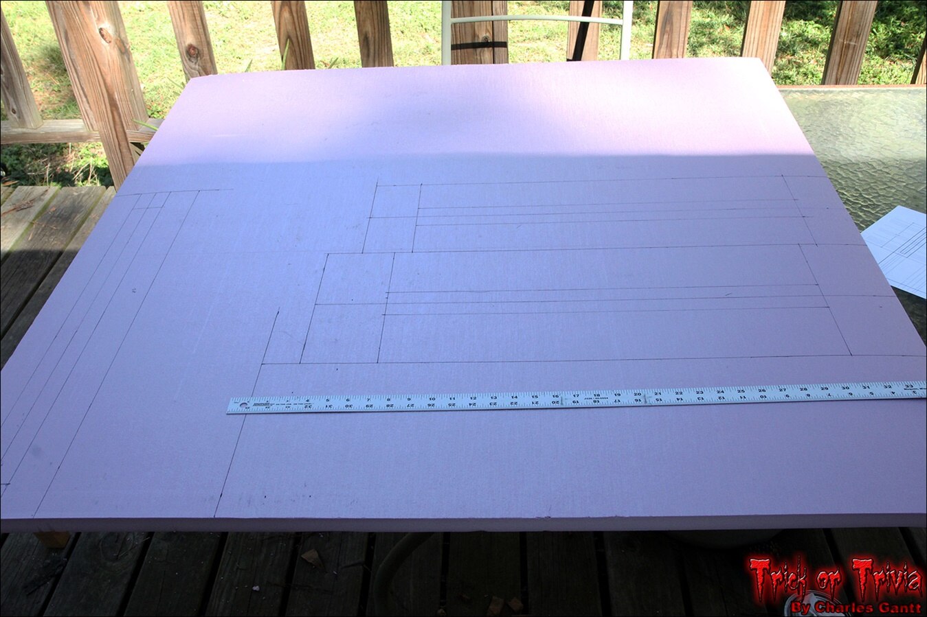
It is important to remember to pull your measurements from one of the factory-square edges. This will ensure that everything aligns nice and square in the end.
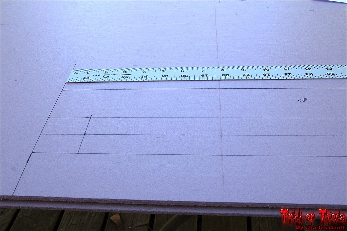
Here you can see one of the major issues with construction insulation foam. It’s built on a tongue and groove design that greatly speeds up installation, and improves its efficiency. This groove is problematic if you plan on using the full 4-foot dimensions of the sheet though. I simply chose to place this piece facing the back so that it is not seen.
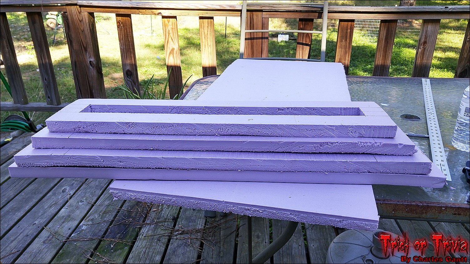
With all of the pieces cut out, I dry-stacked them to test for proper fit. As you can see, the foam warped a little, but since this is supposed to be a 100+ year old tombstone, I am ok with the less-than-perfect look. Before I glue things up though, I need to rough the edges up a little so that they look like they have been exposed to the elements for the last century.
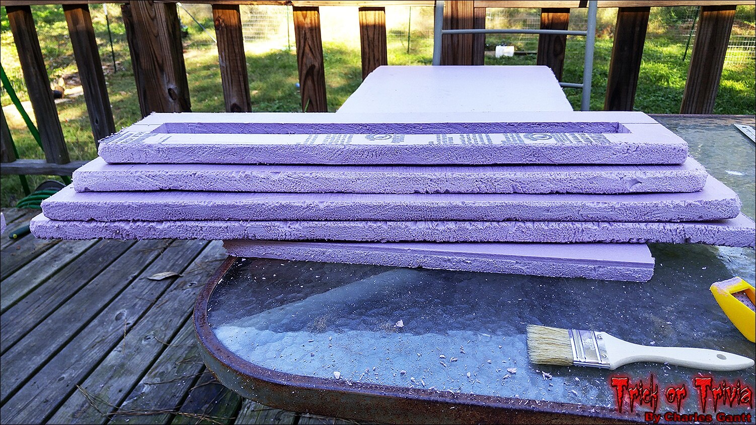
To rough the edges I used the Stanely Shureform Foam Rasp. I practiced on a scrap piece of foam and found a stroke that would not rip the foam, but shave it. After about 10-minutes I was quite pleased with the results.

Now it’s time to glue the base layers together. Again using a liberal coating of Glidden Gripper, I coated each layer, then stacked them together using sharpened popsicle sticks to hold the alignment. Just like the two larger pieces, place this to the side and stack something heavy on top to ensure a proper bond while the glue dries.
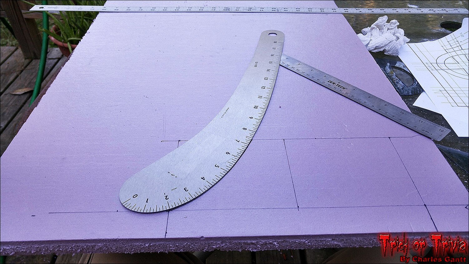
With the base out of the way, it’s time to get to work on the cross that will adorn the top of the tombstone. I began transferring the design over, and used a curve ruler to get the clean lines the base of the cross calls for.
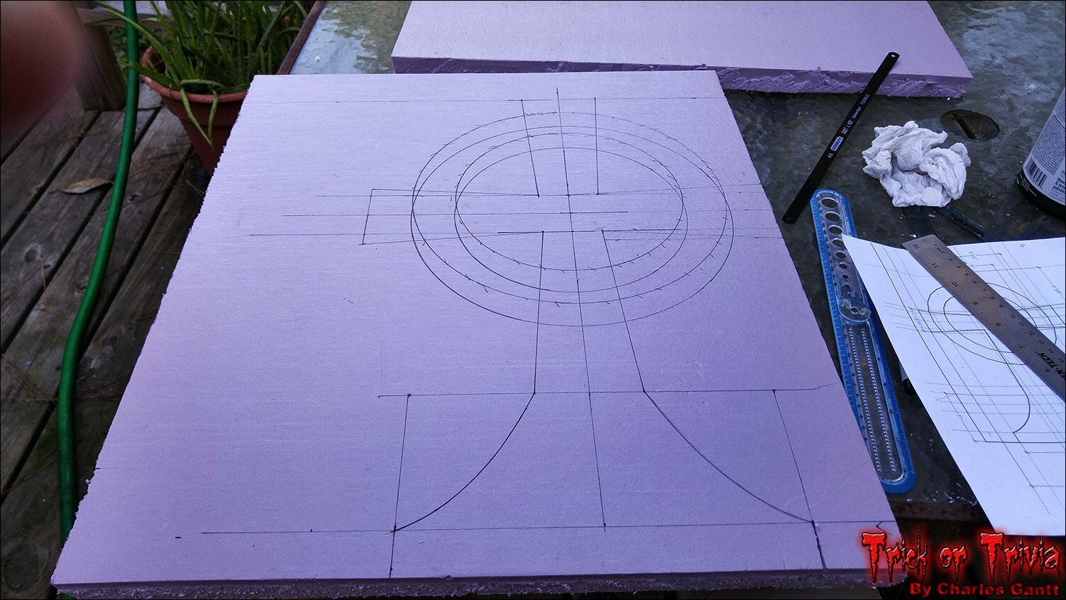
As you can see, I goofed my layout a little, but caught the mistake before cutting anything out. Remember to measure once, and cut twice! I used the blue ruler off to the right to draw the circle. I bought it on amazon years ago, and this was the first time I ever used it. I like it because it allows you to quickly draw a circle of any size up to 12” diameter.
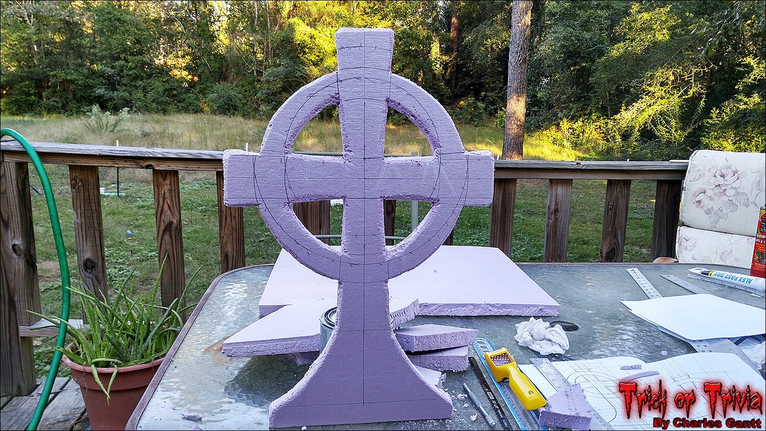
I used a hacksaw blade and hobby knife to cut the cross out. In hindsight I should have used my jigsaw as it would have turned this 25-minute task into a three-minute job. Here you can see that I have already roughed the edges with the rasp, and shaped the cross a little. Now it’s time to add some faux cracks and surface blemishes.
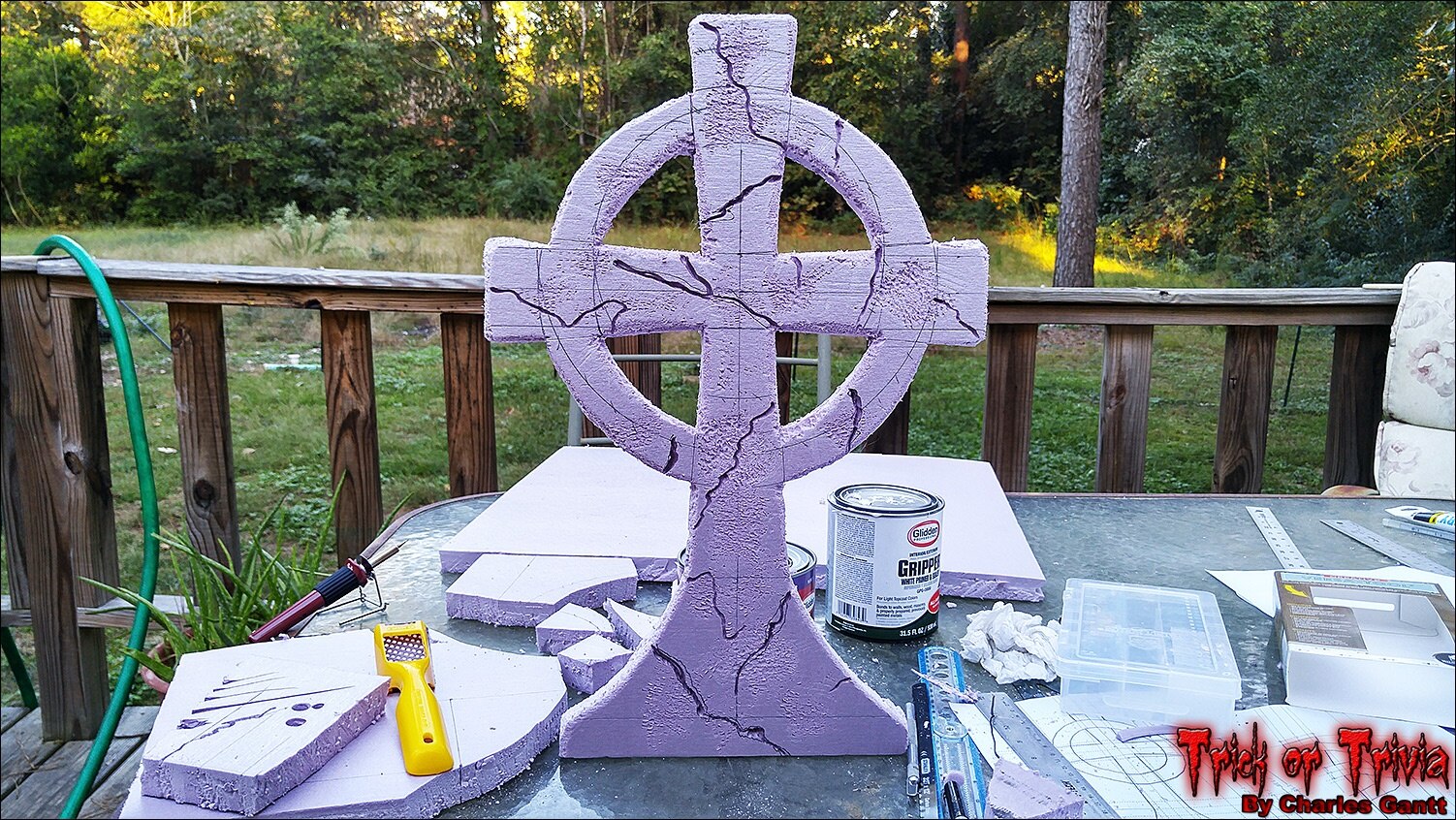
Using a wood-burning tool, and the rasp, I added several cracks and surface blemishes to the cross. This was actually pretty fun, and I was able to really add some fine detail with the conical tip on the wood-burning tool. The surface blemishes were created by pressing the rasp into the surface and twisting it from side to side while pushing up or down at the same time.

I started painting the cross with the stone grey paint. The surface blemishes along with the cracks proved to make this process a little more difficult as the paint had to be “pushed” into the small crevices. I found that the best method was to sort of stab the paintbrush into the cracks, and “wiggle” it on the surface blemishes.
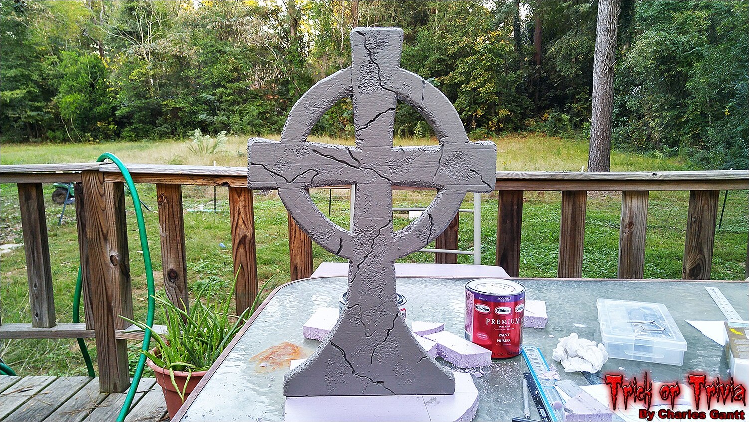
With the cross painted, I sat it aside and let it dry for about 12 hours before applying a second coat. One thing to be aware of is that latex paint will not dry if the humidity is too high, and if any dew falls on the paint before it dries, the paint will stay wet.
I let the cross, the base, and the main tombstone body dry overnight, and well into the next day. I would estimate that things dried for about 14 hours, and unfortunately the Glidden Gripper had not fully dried by the time I got around to laying out the tombstone body. In hindsight, I would much prefer using something like a non-solvent based contact cement to glue the two sheets together. Glidden Gripper is pretty common for gluing foam together, but in general, you should wait about 48-72 hours before it is fully cured.
I was highly frustrated at this point and I forgot to take photos of the tombstone’s layout on the uncut laminated foam sheet. I used the same method to lay it out as I did everything else. I also cut it out using a jigsaw this time as two sheets proved to be a little too difficult to cut with a hacksaw blade by hand.
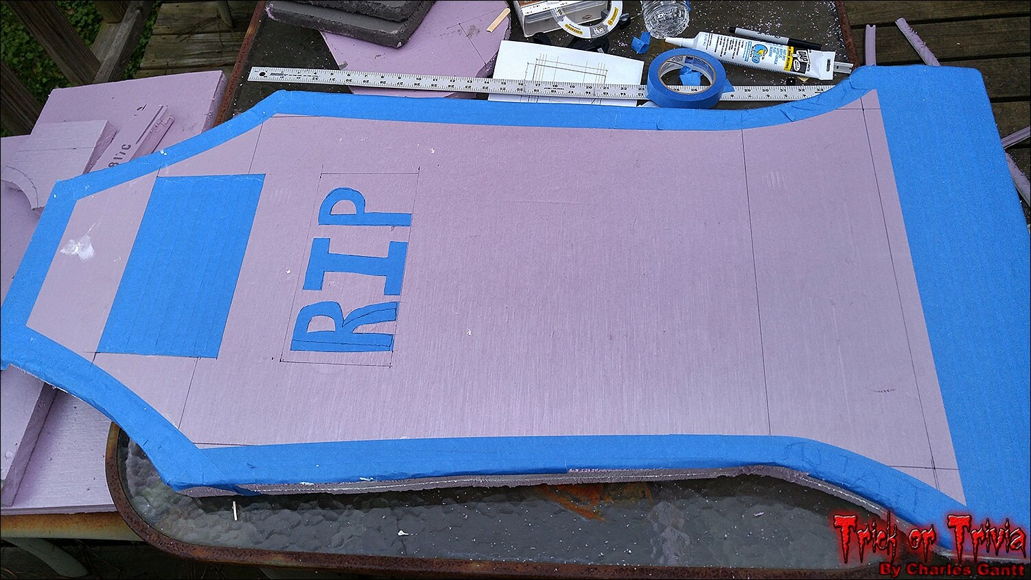
I then lined the edges with blue painters tape, masking off between 1.5 and 2-inches. This was part of a failed experiment to use acetone to melt a significant portion of the surface which would create a relief cut look. As I later found out, new insulation foam like this is coated in a solvent-resistive film that prevents things like construction adhesives, spray-paint and other solvent laced things from eating it away. The big blank spot at the top is where the LCD will mount.
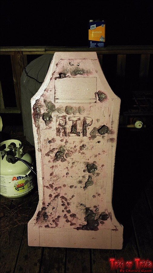
Again being frustrated, I failed to take photos of the next process. I decided to use my plunge router to remove the first ¼-inch of the surface where I wanted the acetone to etch away. Unfortunately, even pure acetone had a hard time etching the majority of the surface, but I did notice that large puddles would eat away portions of the foam, leaving these cool craters behind. So with this new found knowledge I dripped puddles of acetone onto the surface and used the rasp to speed up the chemical reaction by etching where I wanted the craters. As you can see, it gave the tombstone a really cool, aged look. I did make sure to hose the tombstone down to help nullify any remaining acetone residue that might have been hiding.
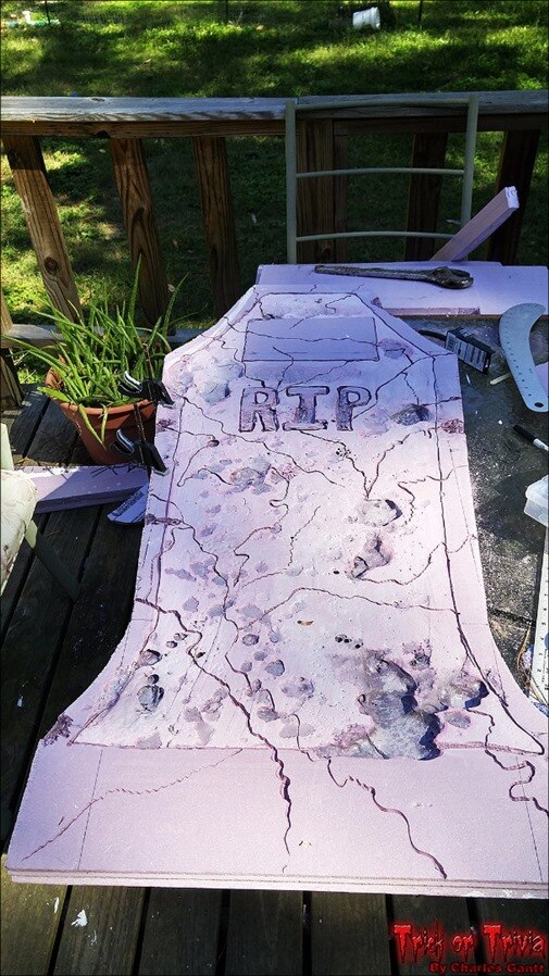
The next morning I set up the wood burning tool again and began creating more faux cracks into the surface of the tombstone. I also took the tool and used it to define the line between the letters, edges, and LCD mounting spot. This made the inside portion really stand out. While it’s not pictured here, I also used the rasp to create more surface blemishes to tie in the tombstone body to the cross.
Before I get to the next part, I want to show you how I prepped the small 5-inch prop skull to be mounted onto the tombstone.
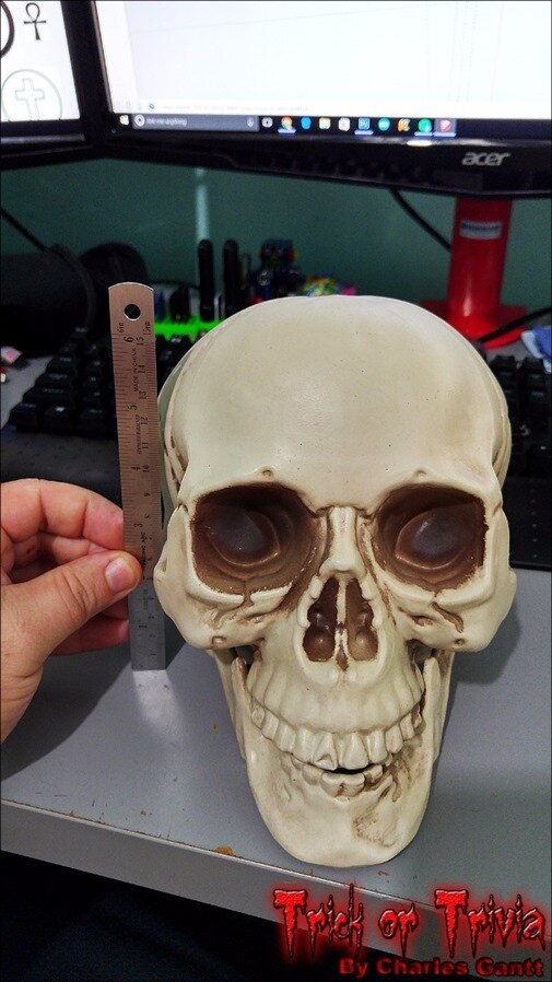
The skull was purchased at Target for about $3, and was the perfect size for a tombstone of this size. I wanted a foam skull, but unfortunately almost every skull you find in the USA is blow-molded.
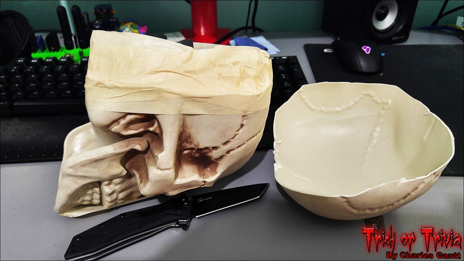
Since I needed a way to firmly attach the skull to the tombstone, I decided to fill it with Great Stuff foam in a can. To allow the foam to expand (it expands by 3-4 times the volume used) I cut the back of the skull off, and then created a 1.5” dam with masking tape. This would ensure that the foam rose high enough above the cut line that I could get a good flat cut later on.
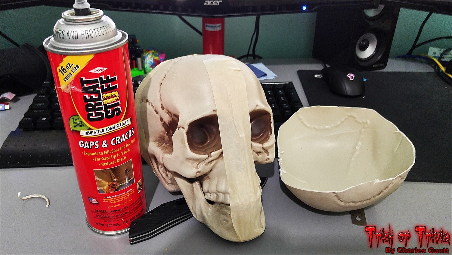
Since the skulls jaw is moveable, I taped it shut in the event that the great stuff foam glued it into place.
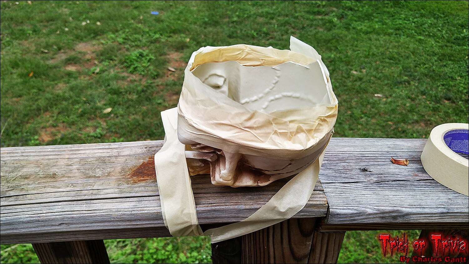
I then taped the skull to the railing on my homes back deck. This allowed me to use both hands when filling it with foam. In hindsight I should have wrapped this rail in plastic from a trash bag or something. I got lucky and no foam dripped off, but it could have turned into a disaster. Great Stuff literally sticks to anything and everything, and is almost impossible to remove.
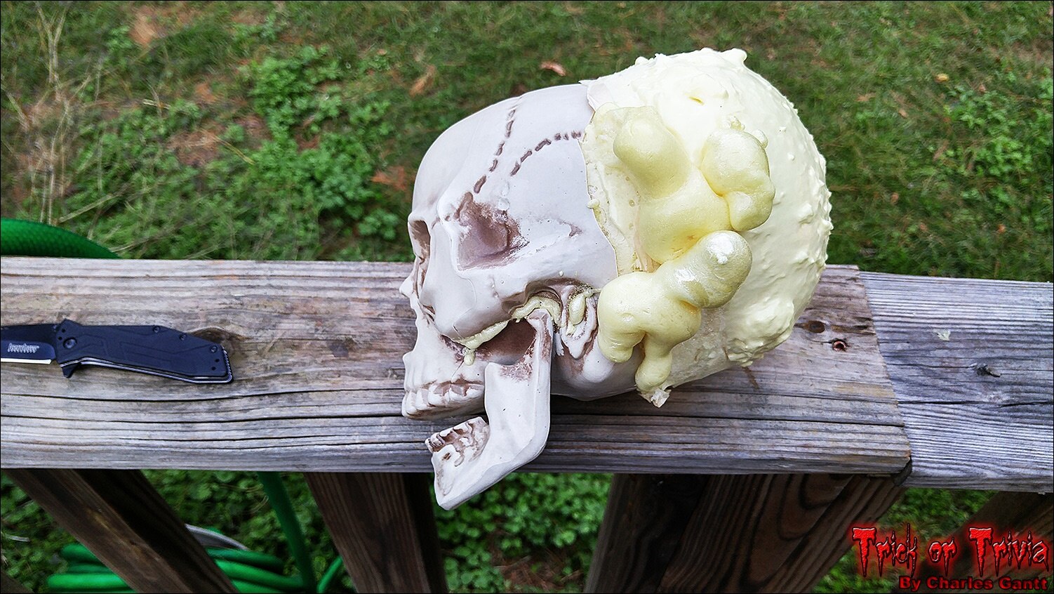
Here you can see the foam expanded. I only filled the skull about half way with the wet foam, and once dry, it was significantly larger in volume. I mistakenly thought that it was fully cured here, and cut the top off at the tape line.
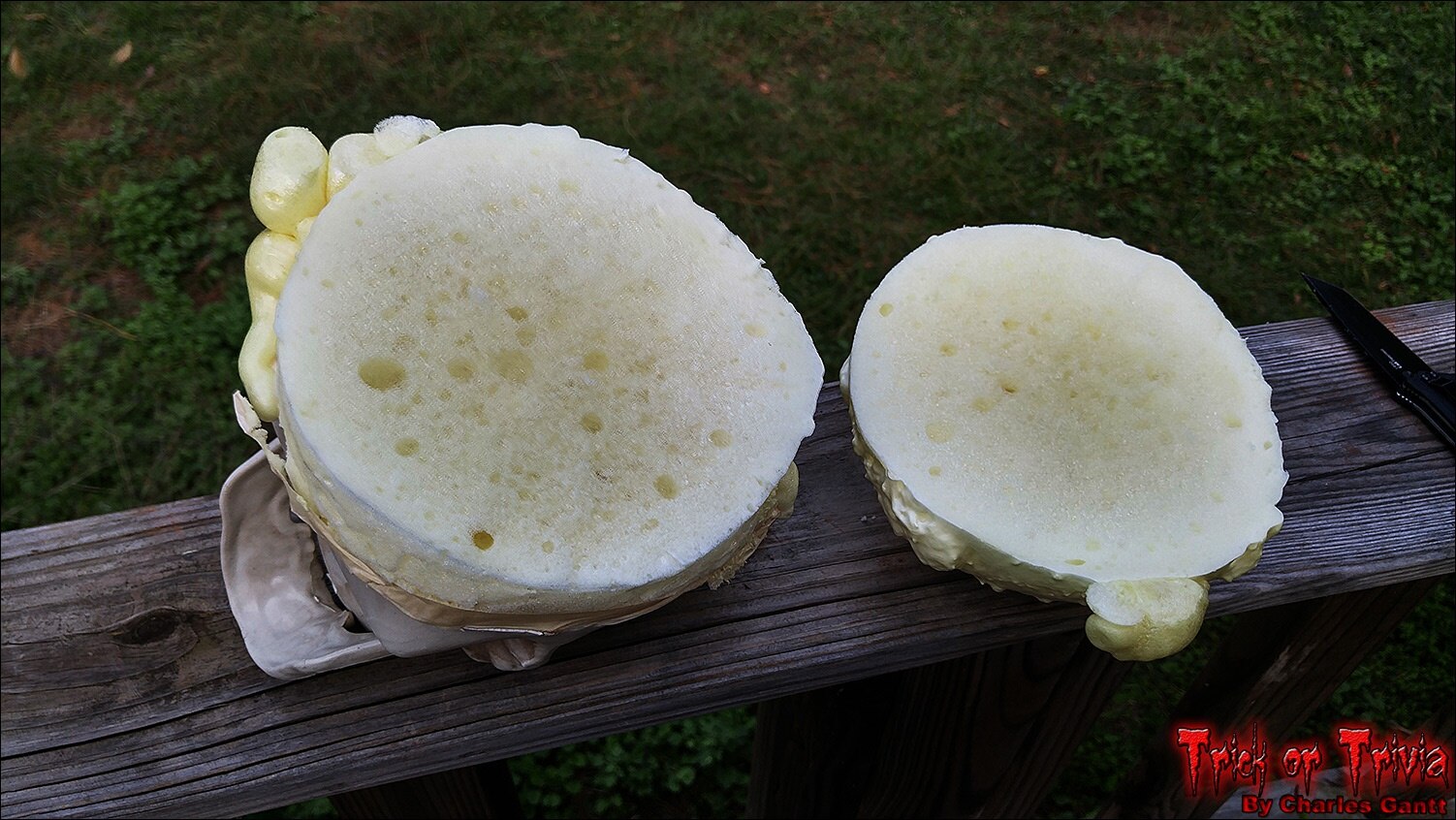
What I did not know was that the foam inside that had not been exposed to air was still liquid. After I took this photo I laid the skull in a box and to my surprise it had expanded more overnight and the foam had squirted out of any crack it could find. This process repeated itself three times. I later found out that I could have layered in wet paper towel strips every inch or so of foam. this would allow moisture to wick in and help cure the foam faster.
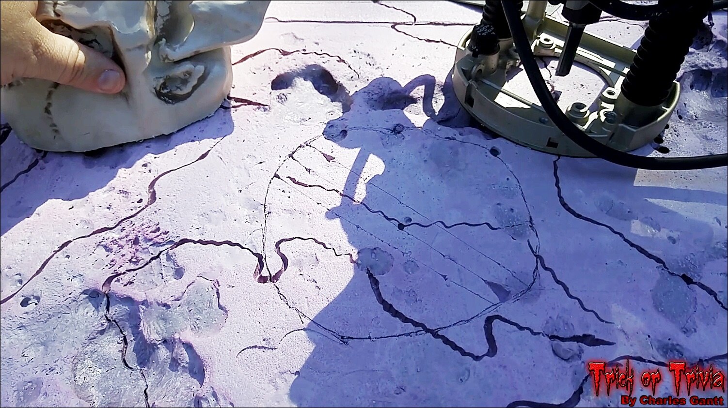
With the foam skull finally cured, I traced its outline onto the tombstone, and used my router to “hog out” the material by about ¾-inch deep.
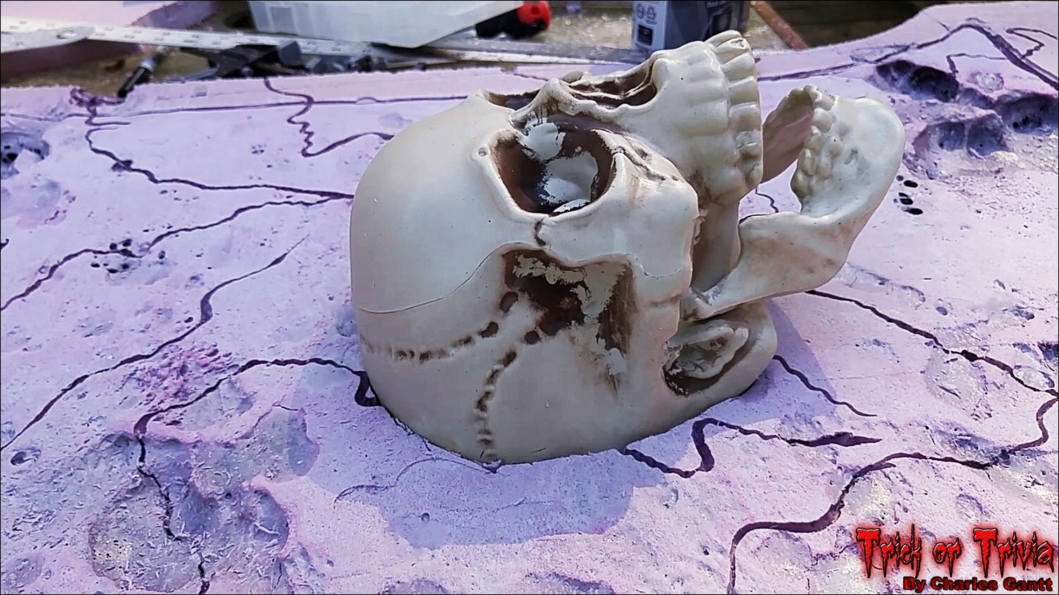
Then I used a low-temp hot glue gun to secure the skull to the tombstone. I used this method because when I tried a few other glues, they did not seem to stick well to the Great Stuff foam as it was very porous. Hot glue worked great, and dried almost instantly.
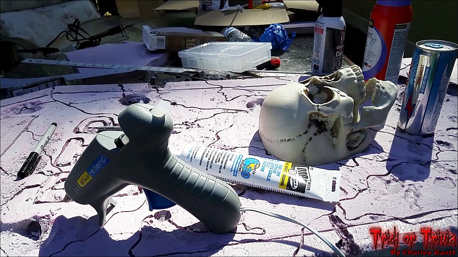
With the skull recessed about ¾-inch into the surface of the tombstone, I used a latex / silicone blend caulking to seal the edges and give it a nice transition to make it appear as if it is part of the stone.
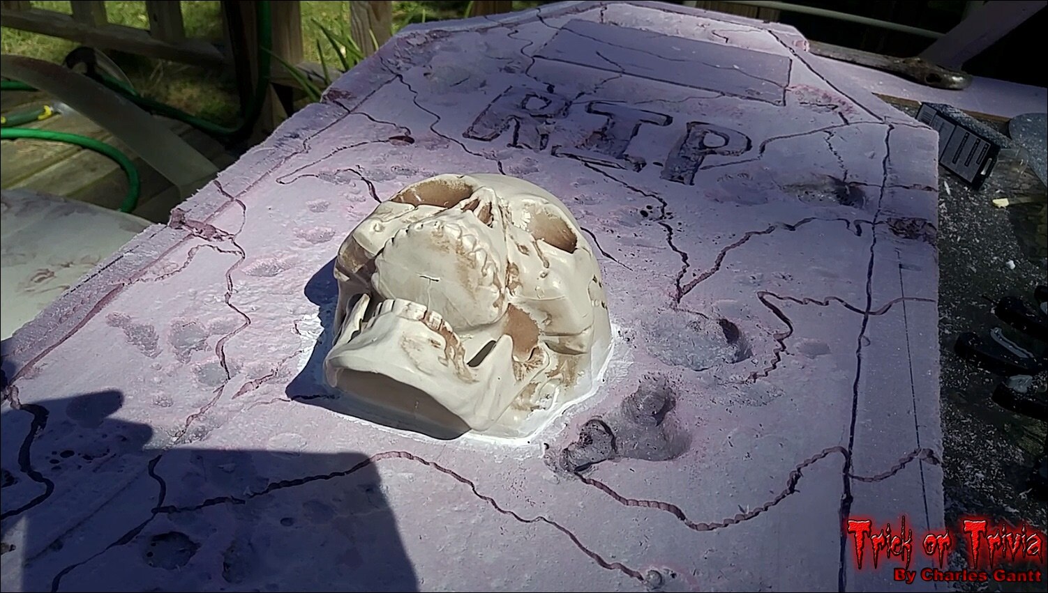
With the skull in place, I could finally begin painting the whole tombstone. Just like the cross, painting in the cracks and surface blemishes proved to be a tough task. I spent two hours making sure that everything was properly coated, and that no pink from the foam was showing.

I apologize for not getting any good shots of the painting process, but it was getting late and I was in a hurry to beat the fast-setting sun. The image above was taken after two coats had been applied, and let dry for about 24 hours.
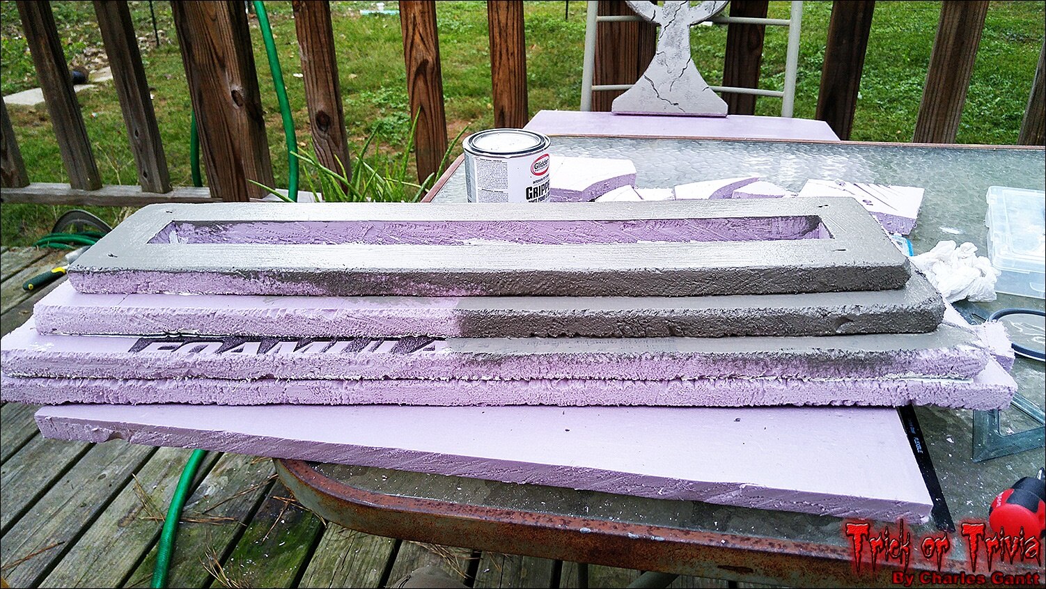
Now it’s time to paint the base. Much like the tombstone and cross, getting paint into this rough surface was challenging, but after about an hour and two coats later, I managed to get everything covered.
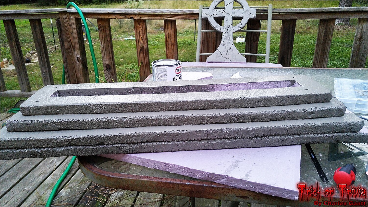
One important thing to mention is that when painting rough surfaces like this, it is paramount that you rotate the piece and check it from every angle. Even after two coats, I still found a few tiny pink spots that I missed.
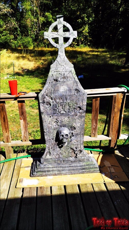
Once again, I do not have any photos of the finishing process. I took about 30 photos of the dry and wet brushing techniques my Girlfriend and myself used to detail the tombstone, but for some reason I lost all 30 of them and four videos I had recorded as well. There are dozens of videos on YouTube and thousands of tutorials on the web that detail these techniques though, so if you are interested in these processes, search for “dry brush technique” and “wet brushing” or “paint washing technique” on YouTube.
Building this tombstone took way more time than I thought it would. All in all, I think I have about 14 hours into its design and construction, and about $140 in materials, tools, and other things I bought for it. While my budget was only $100, I feel that $140 is a fair number since I got some tools, and enough paint to do another 1-2 of these. The biggest thing is the time it took be to build it. Including the waiting times for things like glue and paint to dry, the project took about 4.5 days to complete, which put me way behind on its posting schedule.
That is going to wrap this installment of Project: Trick or Trivia. Check back in a few days for the next installment, where we finally mate the screen to the tombstone, and permanently mount the candy dispenser mechanism. Until then, remember to Hack The World, and Make Awesome!
Project Introduction
Building The Trivia Interface
- Interfacing Ambient and Triggered Audio Events
- Building The Candy Dispenser & Servo Coding
- Carve Foam Tombstone
- October 24th - Assembly and Testing
- October 28th - Project Wrap-up
Originally published by Charles Gantt on Element14 Community
Part 6: TrickOrTrivia #006: Constructing the Candy Dispensing System

Welcome back to the Trick or Trivia Blog. In this installment, I will show off how I built the candy dispenser that will set beside the tombstone. Unfortunately this part of the project did not turn out as I had planned because I could not find the type of bowls I was looking for. I did managed to cobble something together that works, and I will be able to build a better version for next Halloween.
My original idea was to use faux concrete flower urns that typically can be found beside tombstones. I got the idea from some flower vases I saw at the local Hobby Lobby back in July, but was unable to find them again at any store I visited. So I improvised and bought two cheap Halloween Candy bowls, and hacked them into something that would work. While this is not the most refined solution, it worked well in the end.
The Hardware and Tools Needed
Below you will see a list of the hardware and tools used to build the candy dish that catches the dispensed candy.
- Two large bowls of similar size
- 15-20 Sticks of Hot Glue
- Hot Glue Gun
- 6”x6” Square of Plywood
- Knife or Scribe
- Shims Made from Scrap Cardboard.
Installing The Touchscreen
Before we get started on the candy dispenser, I wanted to quickly show you how I installed the touch screen into the Tombstone. I spent a lot of time mulling over how to mount the screen, and after several different mockups, I decided on just using hot glue to secure it. Unfortunately during the time I moved to my new home, and the time I began working on this (a week later) I found that the Raspberry Pi Screen had cracked after a heavy box had been stacked on top of the box the screen was wrapped up in. So I had to order a new screen and wait on it to arrive.
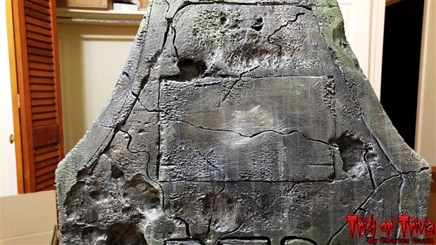
You might remember that when I carved out the tombstone, I left a square patch near the top, fairly blank. This is the place where I cutting out the recess for the screen.
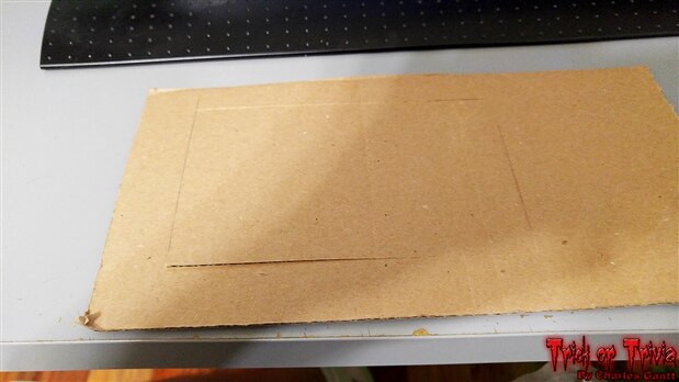
To get started I transferred the screen’s metal housing dimensions to a piece of scrap cardboard. I then cut out the waste cardboard, and checked the screen for fitment.
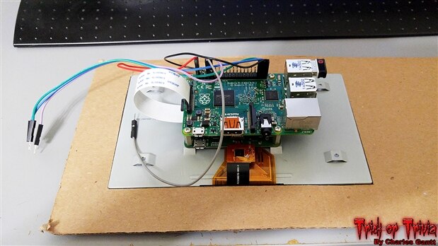
As you can see, the screen fit perfectly inside the template.
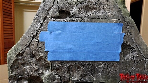
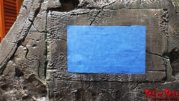
The next step is to cover the flat part on the tombstone with painters tape. This will give us somewhere to trace out the rectangle we need to remove.

After eyeballing the placement, I traced the rectangle onto the painters tape. I tried to keep this as centered as possible, but in the end it was off a little, but no big deal as it is a 100+ year old digital tombstone!
Next I use a razor knife to trim the excess tape away. This gives me a clean line to follow when cutting out the foam.
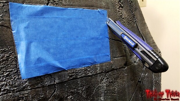
Using a cheap box cutter I was able to remove the foam rectangle with little trouble. If I had to do this again, I would have used a jig saw to cut this out as the cut would have been easier.
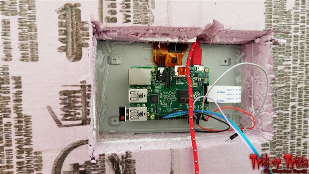
Finally, a shot from the back showing how I used hot glue to secure the screen in. I am withholding the shot of the screen installed from the front until the next installment of this series.
Building the Candy Dispensing System.
The heart and soul of this project was the touch screen, but we can not forget the reward that we owe the children who visit us on Halloween night. When I originally prototyped the candy dispensing system, I had a plan in mind that would utilize a faux flower urn and smaller candle dish to hide the dispenser. The Dispenser was planned around that urn, and its dimensions. Unfortunately I was unable to find that style flower urn for sale when the time came to buy it despite several being on the shelves of Hobby lobby just days before. I would not let that stop me though, and I improvised with two large candy bowls from the dollar store.
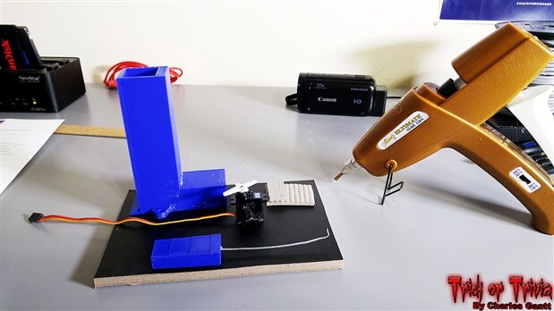
To get started, I needed to find a suitable piece of scrap wood. Fortunately I found this piece of ⅜” thick hardboard laying around from an old cheap book shelf we had planned to throw away. I cut a suitable sized piece off and heated up my glue gun.
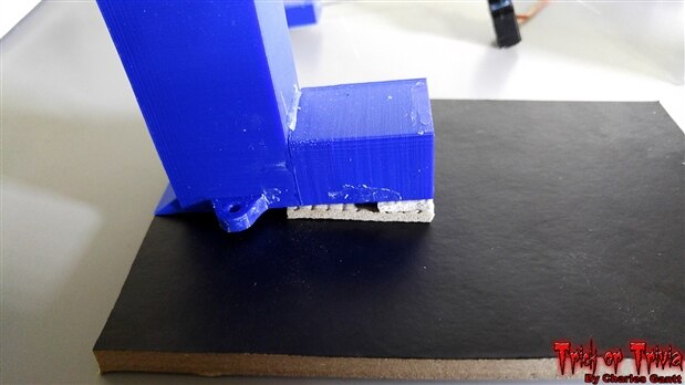
While the glue gun was heating, I mocked the dispenser hopper up, and found some scrap foam to use as a shim to set it at an angle. You can use cardboard or even dry hot glue to raise the back of the hopper up.
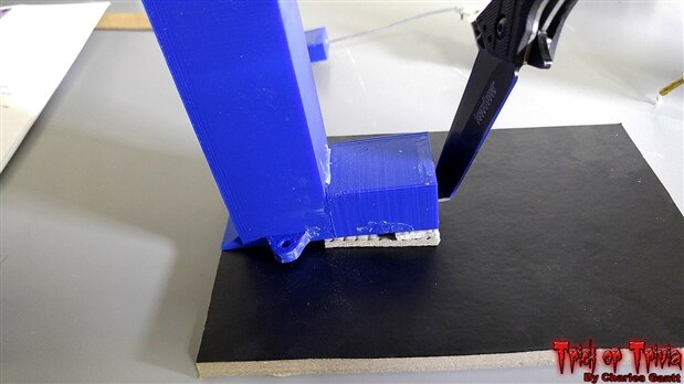
With the angle set, I used a knife to trace an outline of the foam so I could remove the paper covering. I did this because I know from past experiences that hot glue does not stick to this surface very well.
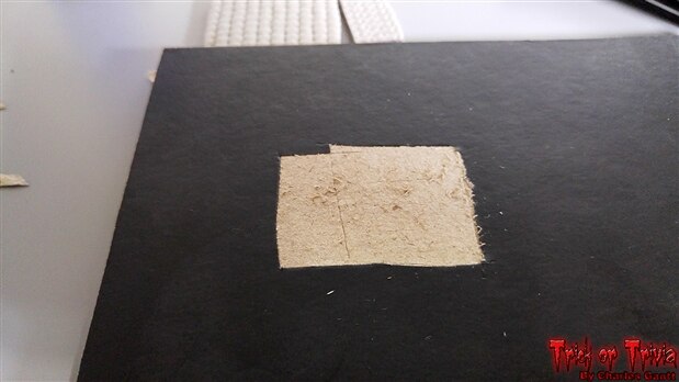
Then I simply cut through the black paper layer, and used my knife to rough it up a little for better glue adhesion.
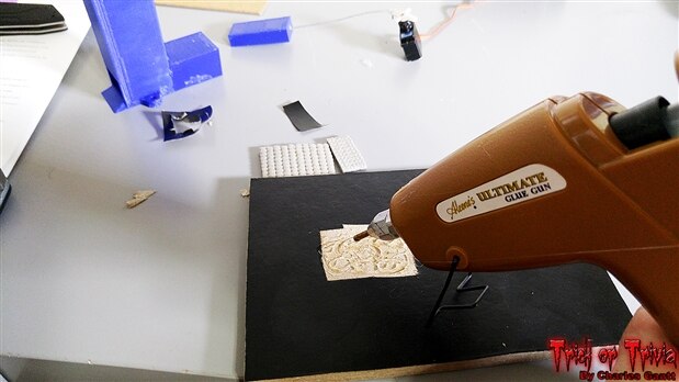
I then added hot glue to the roughed up surface. The glue sticks I am using are considered “High Temp” meaning they melt around 350f, and honestly they were a little too hot for the foam I used, but they are all I had. In retrospect, I should have used “Low Temp” glue sticks.
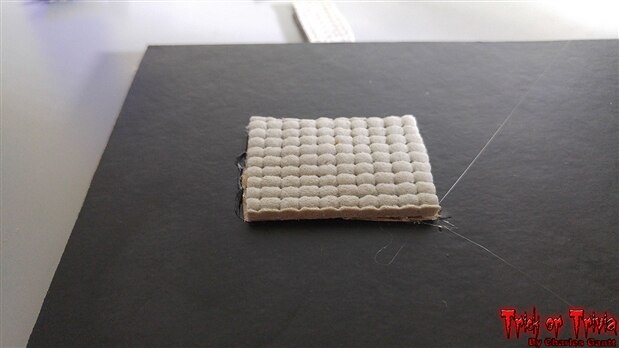
I then placed the foam on top of the glue. One of the bad things about using “High Temp” glue sticks is that you will get burnt instantly if any squeezes out the sides and comes in contact with your finger. This is much less of an issue with “Low Temp” glue sticks. I buy these sticks by the 25lb box, so I have an abundance of them.
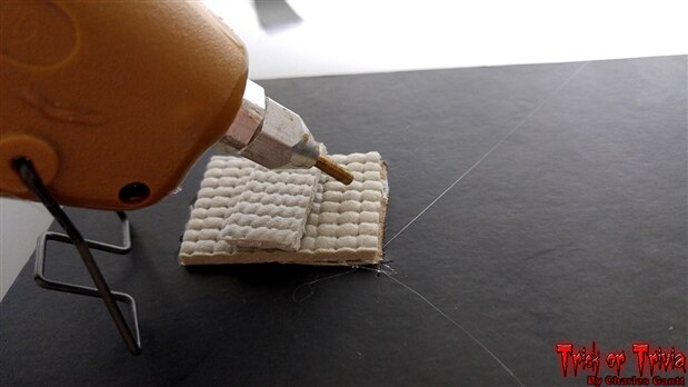
Next I glued the smaller foam strip down. This part was tricky as the high temp sticks are hot enough to melt this foam. I let the glue gun cool down some before applying any glue.
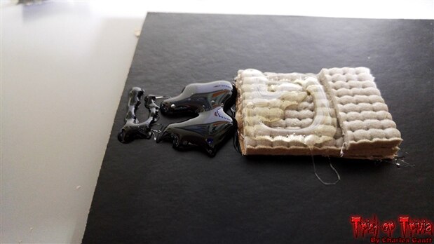
For the next part, I managed to find a low temp glue stick in my Girlfriend’s craft room. I knew I would melt the foam with the high temp sticks. I should have removed the black paper here as well but I got into a rush and forgot to cut it out until it was too late.
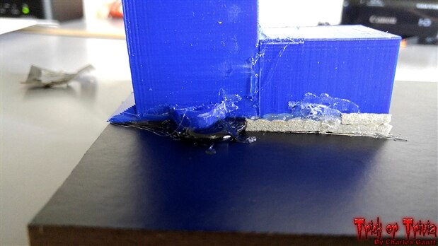
Finally I glued everything down and held pressure on it until the glue cooled. It looks very messy here, but I did clean it up a bit.
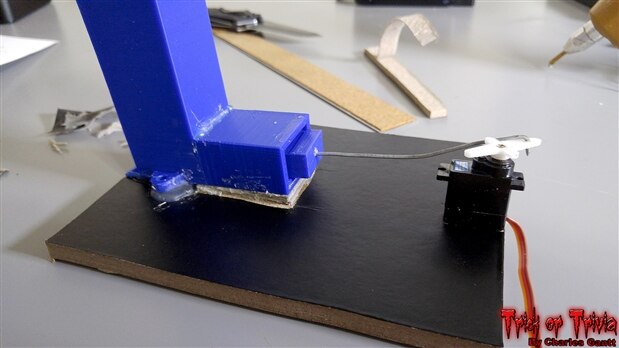
With the hopper secured in place, I was able to mock up the servo placement. It took a few tries, but I finally managed to get the edge of the board trimmed down enough so that the plunger was able to travel enough to eject the candy.
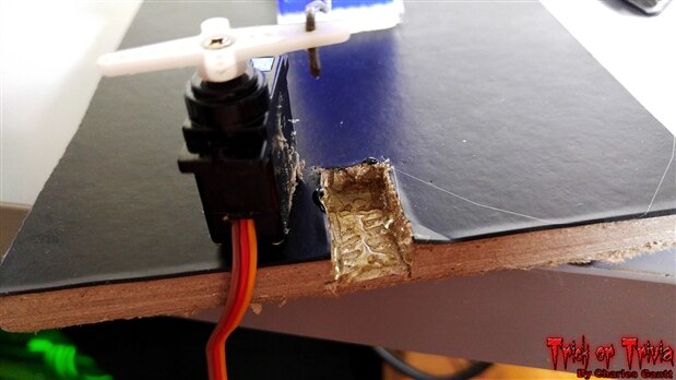
With the optimal placement found, I used my used my knife to carve out a hole that the servo could fit inside. Then I used hot glue to secure things.
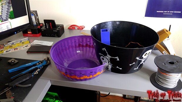
With the candy dispenser assembly completed I moved on to modifying two bowls. Basically I cut a relief into the bottom of the black bowl, and a similar relief into a side on top of the other bowl. I then used about 20 glue sticks to secure everything together.
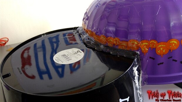
I am not going into much detail on this bowl design on purpose as I feel that the odds of someone finding similar bowls is slim to none, and there is surely a better way to do this. Here you can see that I have placed the glue about one inch up on the purple bowl and let it “flow” onto the black bowl about an inch as well. I did the same on the inside.
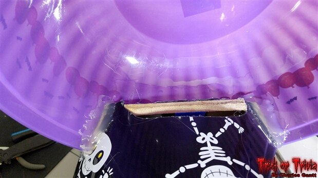
Here you can see how I layered the glue on the inside of the two bowls.
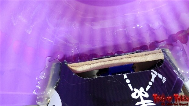
One more shot of the inside. You can almost make out the candy hopper.
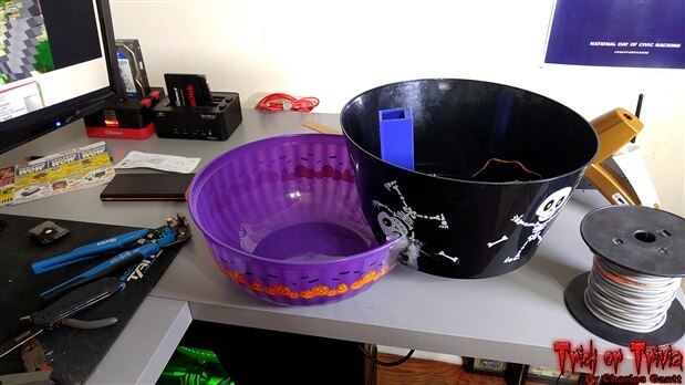
And a final shot of the bowls pared together. You can see the hopper in the big bowl, and the candy feeds into the smaller bowl. Both of these will be perched on a stand beside the tombstone and the black bowl will have a jack-o-lantern cover as to hide the dispenser.
That is going to wrap this installment of Project: Trick or Trivia. Check back in a few days for the next installment, where we bring everything together, and demo the system working. Until then, remember to Hack The World, and Make Awesome!
Originally published by Charles Gantt on Element14 Community