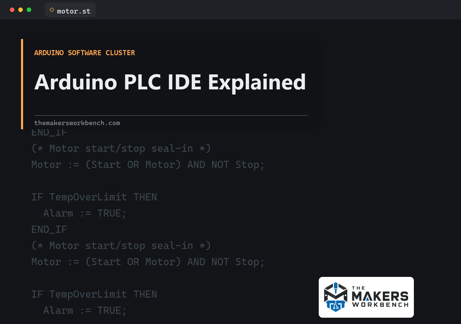
If you have been blinking LEDs in Arduino IDE 2, Arduino PLC IDE looks like it wandered in from a factory floor. The window is denser. The languages have names like Ladder Diagram and Structured Text. There is a license to activate on the hardware. That is not a skin on IDE 2. It is a different programming tradition, aimed at Arduino's industrial boards: Opta and Portenta Machine Control.
A PLC, a programmable logic controller, is the rugged little computer that runs a station on a packing line, a set of pumps, or the heating and cooling equipment in a building's mechanical room. Factory electricians have used PLCs for decades. The software tradition around them is IEC 61131-3, an international standard that defines several languages for that work. Arduino PLC IDE is Arduino's Windows environment for speaking those languages on Arduino industrial hardware, and for mixing them with Arduino sketches.
This article is the explainer. What the IDE is, what a scan cycle is, what the five languages are in plain terms, which boards it talks to, how licenses work, where Modbus and CAN fit, and why you should not install this to program an Uno. Current version on Arduino's software page: 1.1.0. It is free to download. It is Windows 10 64-bit or newer only. There is no macOS or Linux build.
If you are still choosing maker boards vs industrial hardware, Part 2 of the Mastery Series is the family conversation. Opta is not a slightly tougher Uno. It is a micro PLC with industrial I/O and a different software door.
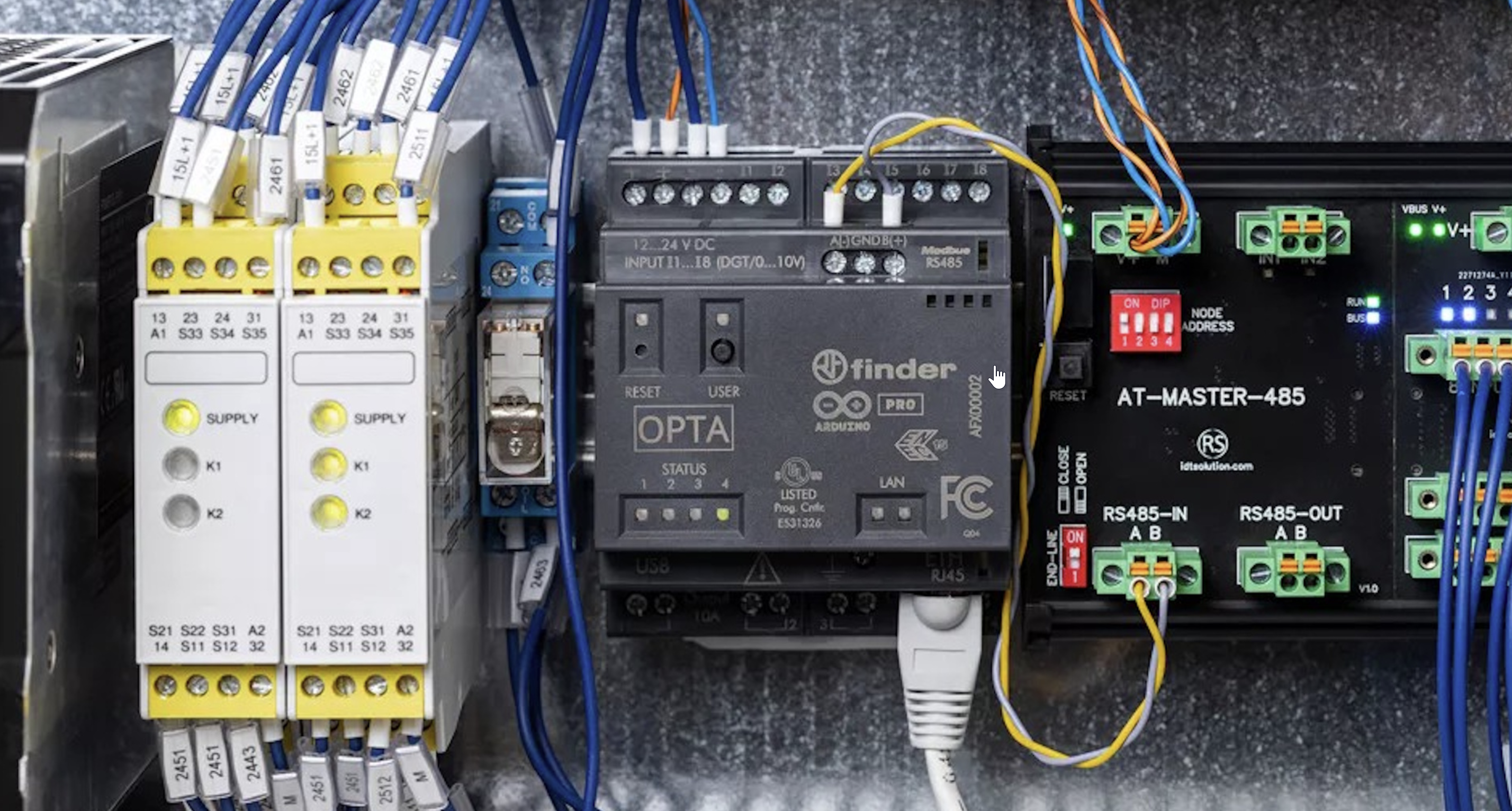
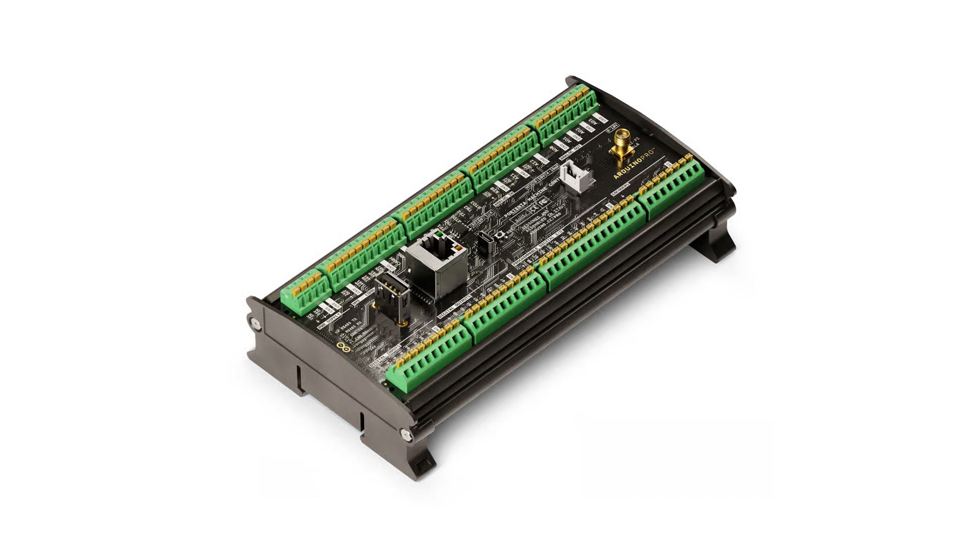
Image: Arduino
Image: Arduino
What is Arduino PLC IDE?
Arduino PLC IDE lets you program compatible Arduino PLC devices using the IEC 61131-3 languages, and it includes an editor for Arduino sketches in the same project. Arduino's product page lists five languages: Ladder Diagram, Function Block Diagram, Structured Text, Sequential Function Chart, and Instruction List. You can share variables between the PLC side and a sketch. You get cyclic tasks (work that repeats on a timer, which is how PLCs think) and fieldbus configurators for CANopen, Modbus RTU, and Modbus TCP.
Fieldbus, here, means the industrial networks machines use to talk to sensors, drives, and other controllers. Modbus RTU is Modbus over a serial line (often RS-485, a sturdy two-wire serial standard that can run hundreds of meters across a noisy factory). Modbus TCP is Modbus over Ethernet. CAN (Controller Area Network) and CANopen are the bus family you meet on vehicles and a lot of industrial I/O. Arduino documents no-code-ish configurators for those in PLC IDE, plus pin mapping and memory partitioning tutorials for using the same hardware with the rest of the Arduino toolchain.
Version 1.1.0 (March 2026) added remote lifecycle pieces for Opta, including over-the-air updates of the PLC program via Modbus TCP on Ethernet, even through a VPN (a secure, encrypted tunnel into a remote network). It also simplified Opta's serial ports: with Opta package 1.3 and PLC IDE 1.1.0, Opta exposes one COM port by default for runtime install and Modbus, instead of two. Portenta Machine Control still typically shows two ports. Arduino's help center says to pick the lower-numbered port when you configure Modbus on that board.
The IDE is closed-source, unlike Arduino IDE 2. Download is still free. IEC 61131-3 programming on the hardware needs a lifetime license key for that device, sold in Arduino's store. The first official tutorial is literally setup and device license activation. If you skip that, the editor will install and the board will not become a PLC target.
This is not Arduino IDE 2
Arduino IDE 2 writes a sketch, compiles it, and uploads firmware. setup() runs once. loop() runs as fast as it can, unless you delay() or write a non-blocking pattern. Part 3 is that model.
A PLC does not think in loop(). It thinks in a scan cycle:
- Read the inputs (physical terminals, and values from a fieldbus).
- Run the logic (ladder, structured text, or whatever you wrote).
- Write the outputs.
- Repeat, on a schedule you configured.
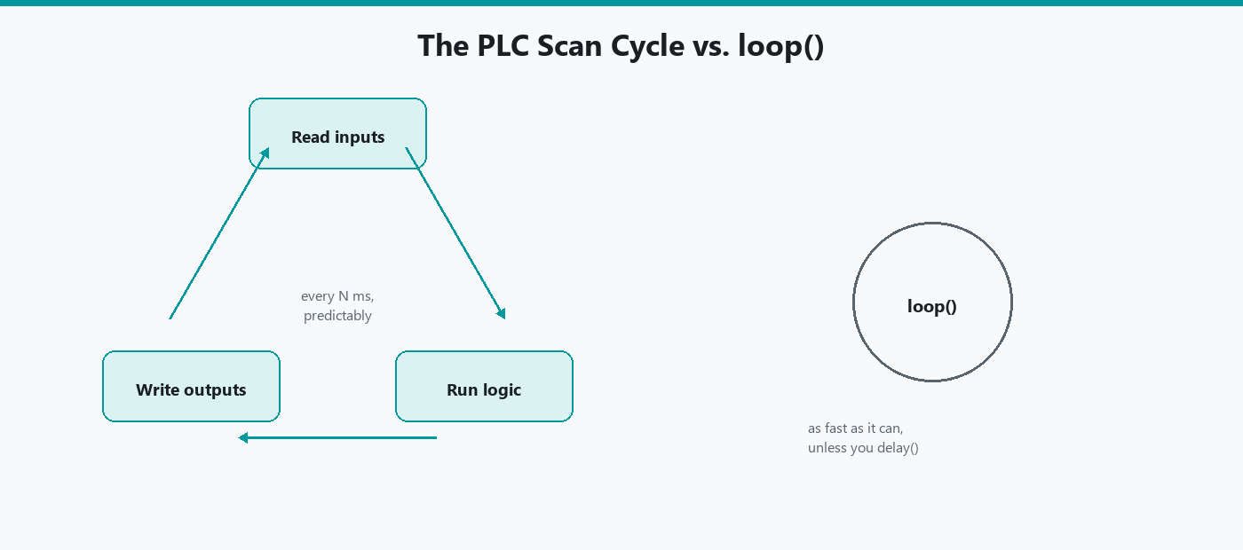
That cycle is meant to be predictable. A motor starter should not wait because you printed too much to Serial. Arduino sketches can share the device with that cycle (Arduino documents mixing sketches and IEC languages, and memory partitioning). They are still two models living on one piece of hardware.
If you open PLC IDE because you saw "IDE" and you have an Uno on the desk, stop. Compatible devices are Opta and Portenta Machine Control (and the expansions Arduino documents for Opta). A regular Uno is the wrong target.
You can still use Arduino IDE 2 with Portenta Machine Control for sketches. Arduino's Machine Control user manual is explicit: that manual is the Arduino IDE path; IEC 61131-3 is the PLC IDE tutorial path. Same hardware, two doors.
What is IEC 61131-3?
IEC 61131-3 is the part of the IEC 61131 PLC standard that defines programming languages. You do not need to buy the standard to start. You need the five names and what they look like, because PLC IDE will offer them and factory people will use the abbreviations.
Ladder Diagram (LD). Looks like the relay schematics electricians already knew how to read: contacts in series and parallel, coils as outputs. A "rung" is one horizontal line of logic. If you have ever traced a control panel drawing, ladder will feel less foreign than C++. If you have only written if statements, ladder is a drawing of those ifs.
Function Block Diagram (FBD). Boxes and wires. Each box is a function (a timer, a comparison, a PID block, which is a ready-made controller that nudges an output until a measurement hits its target, like a thermostat that does not overshoot). Wires carry values between boxes. It looks like a schematic for software.
Structured Text (ST). Looks closer to Pascal (an older, very readable language that used to be taught in schools) than to Arduino C++. You write IF … THEN … END_IF, assignments, function calls. People who like text over drawings live here. It is still a PLC language with PLC types and the scan cycle underneath, not a sketch.
Sequential Function Chart (SFC). Steps and transitions. Useful when a machine has a sequence: fill, heat, hold, empty. Each step is a state. A transition is the condition that moves you to the next step.
Instruction List (IL). A low-level, assembly-like list of instructions. Older, still in the standard. Many new projects skip it. Arduino still lists it because the standard includes it.
The easiest way to feel the difference is one job written three ways. The job is the classic motor start/stop circuit: press Start and the motor runs, and it keeps running after you let go of Start, until someone presses Stop. Electricians call that "latching" or a "seal-in."
Here it is as an Arduino sketch, the way you would write it after the Mastery Series:
const uint8_t START_PIN = 2;   // Momentary Start button (reads HIGH when pressed)
const uint8_t STOP_PIN  = 3;   // Momentary Stop button (reads HIGH when pressed)
const uint8_t MOTOR_PIN = 8;   // Output to the motor relay

bool motorOn = false;          // Remembers whether the motor should be running

void setup() {
  pinMode(START_PIN, INPUT);   // External pull-down resistors assumed on both buttons
  pinMode(STOP_PIN, INPUT);
  pinMode(MOTOR_PIN, OUTPUT);
}

void loop() {
  bool start = digitalRead(START_PIN);  // Read inputs
  bool stop  = digitalRead(STOP_PIN);
  // Run on Start, OR keep running if already on, but never while Stop is pressed
  motorOn = (start || motorOn) && !stop;
  digitalWrite(MOTOR_PIN, motorOn);     // Write output
}
Here is the same logic in Structured Text. Notice there is no loop(). The PLC runs this once per scan, forever, and it already read the inputs for you before the line runs:
(* Runs once every scan cycle. Start, Stop, and Motor are mapped to real terminals. *)
Motor := (Start OR Motor) AND NOT Stop;
And here it is as a ladder rung, drawn in plain text. Read it left to right like current flowing through switches to a coil. | | is a normally open contact (passes power when that input is on), |/| is a normally closed contact (passes power when that input is off), and ( ) is the output coil:
   Start       Stop           Motor
|---| |----+---|/|-------------( )---|
           |
   Motor   |
|---| |----+
The lower branch is the seal-in. Once Motor is on, its own contact keeps the rung powered after Start is released. Pressing Stop opens the |/| contact and breaks the rung. An electrician can read that drawing at a glance, which is exactly why ladder is still everywhere.
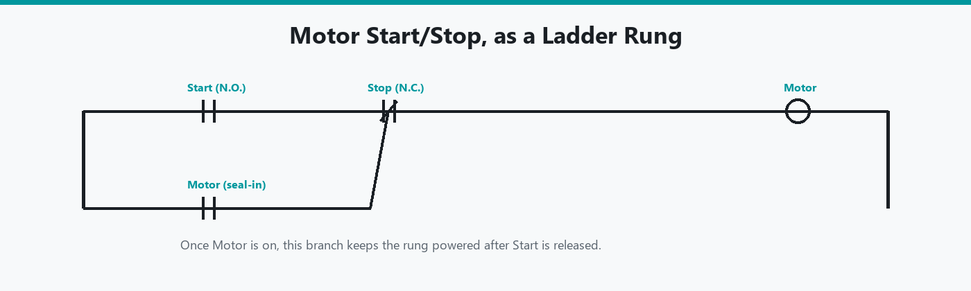
A later article in this cluster can teach ladder and Structured Text to Arduino programmers in depth. For now, notice that all three versions assume inputs, outputs, and a repeating scan. The PLC versions just make the scan part of the system instead of something you write yourself.
Hardware: Opta and Portenta Machine Control
Opta is Arduino's micro PLC. It clips onto a DIN rail (the standard metal mounting strip inside every electrical cabinet) and comes in variants with Ethernet, RS-485, and Wi-Fi, depending on the SKU (the specific product version you order). Expansions add more digital or analog points. PLC IDE has dedicated tutorials for those expansions.
Portenta Machine Control is a larger industrial controller: more I/O, temperature probe inputs (RTDs and thermocouples, two kinds of industrial temperature sensor that work from resistance and from a tiny generated voltage, respectively), and the kind of connector set you expect in a cabinet, not on a breadboard. Arduino has PLC IDE tutorials for RTDs, Modbus TCP with Opta, Modbus RTU, CAN, and a tank-temperature application note that uses both products together.
Both need the PLC runtime on the device: a program PLC IDE talks to, not a Blink sketch you uploaded from IDE 2. First-time setup is: install PLC IDE on Windows, connect USB, download the runtime, activate the license, then set communication (often Modbus on a COM port). Arduino's help article for "PLC IDE isn't working" is mostly about picking the right COM port after that runtime is on the board.
Gotcha: after the runtime is installed, the USB serial layout can change. Opta (package 1.3 / PLC IDE 1.1.0) shows one port. Portenta Machine Control often shows two. If many COM ports are listed, unplug other USB-serial gadgets and use Project → Refresh current target. If two ports appear as COM20 and COM21, Arduino says they likely both belong to the PLC; use the lower number for Modbus setup.
Licenses
The IDE download is free. Programming the hardware in IEC 61131-3 needs a license tied to the device. Arduino sells lifetime keys in the store. The activation tutorial is the first thing to follow after install. Without it, you will think PLC IDE is broken when the target will not activate.
I am not going to quote prices. They change. Check the store page for Opta and Portenta Machine Control PLC IDE licenses when you buy the hardware. Budget for the key, not only the controller.
Sketches inside PLC IDE
You can mix an Arduino sketch with PLC languages in the same project and share variables. That is the bridge for people who already think in digitalWrite and need a Modbus map or a ladder interlock around it.
Use the sketch for something Arduino libraries already do well. Use IEC languages for the cyclic control that a panel electrician will have to read later. Do not put the entire machine in loop() "because I know C++" if the rest of the plant is ladder. The next person to maintain it will not thank you.
Memory partitioning matters if you also want Arduino IDE 2 on the same device. Arduino has a tutorial for that. If you skip it, one toolchain can starve the other. Read that guide before you treat the controller as both a sketch target and a PLC.
Modbus, CAN, and Cloud
PLC IDE's fieldbus configurators are why this IDE exists for cabinet work.
- Modbus RTU: serial, often RS-485, master/slave or client/server depending on how the docs phrase it. Portenta Machine Control and Opta RS-485/WiFi SKUs are the usual pair.

-
Modbus TCP: same protocol on Ethernet. PLC IDE 1.1.0 can also push program updates over Modbus TCP (OTA: over-the-air, here meaning over the network, not Wi-Fi specifically).
-
CAN / CANopen: configurator in the IDE. Separate tutorial on Arduino's PLC IDE docs tree.
Cloud integration exists in the PLC IDE docs as well. That is Arduino Cloud talking to industrial hardware, not IoT Remote as your first download. If the goal is a phone dashboard on an Uno R4 WiFi, you want Arduino Cloud and IoT Remote, not PLC IDE.
Retentive variables: what survives a power loss
This is a real gap between how an Arduino sketch and a PLC program think about their own memory, and it is worth understanding before you wire anything that matters.
On a classic Arduino sketch, every ordinary variable resets when power is lost. motorOn in the sketch above goes back to false on the next boot no matter what it was the instant before the outage, because setup() runs from scratch and the variable's declaration runs with it. That is fine for a lot of maker projects. It is not fine for a machine that needs to remember, say, how many parts it had counted before the lights flickered.
IEC 61131-3 has a built-in answer for this: retentive variables, sometimes marked VAR RETAIN in Structured Text or with a similar flag in the variable table. A retentive variable's value is written to non-volatile memory on the device, so it survives a power cycle and comes back exactly where it left off when the controller boots again. PLC IDE exposes this as a property you set per variable, not a library you install. A part counter, a "was the machine mid-cycle when it lost power" flag, or a fault log entry are the kinds of values that belong in retentive memory. A value that should always start fresh, like a debounce timer, should not.
Getting this wrong in either direction causes real problems on a real machine: a non-retentive part counter resets to zero every time a breaker trips, quietly losing the plant's production count, while an accidentally retentive value that should have reset can leave a machine "remembering" it was mid-cycle after a power loss and doing something the operator does not expect the moment power returns. Decide, for each variable, whether "the machine should remember this through an outage" is true or false, and set the flag to match. Do not leave it at the default and assume it did the right thing.
Testing logic before you wire real I/O
PLC IDE, like most IEC 61131-3 tools, supports running your program in simulation against the target before you have wired a single physical input or output. That matters more here than it would for a sketch, because a PLC program controlling real machinery is the kind of thing you want to prove correct on a screen before a motor is actually connected to the output you are testing.
The practical version of this: write your ladder rung or Structured Text, download it to the target, and force the input variables on and off from within PLC IDE's own interface rather than a physical switch, watching whether the output variables respond the way the drawing says they should. The seal-in circuit from earlier in this article is a good first thing to prove this way: force Start on, confirm Motor turns on, release Start, confirm Motor stays on, force Stop on, confirm Motor turns off. Four checks, no wiring, and you already know the logic is right before a single wire touches a terminal block.
This habit pays off most on anything with more than one or two rungs. A machine sequence with several interlocking conditions is much easier to debug by forcing variables at a desk than by chasing a physical switch on a cabinet while a colleague watches for what the output does.
Who needs Arduino PLC IDE?
You need it if:
-
You have Opta or Portenta Machine Control, or you are specifying them for a machine.
-
You need ladder, Structured Text, or another IEC 61131-3 language.
-
You need Modbus or CAN in the way industrial tools configure those buses.
-
You are an electrician or automation person who already thinks in scan cycles, and you want that on Arduino hardware.
You do not need it if:
-
Your board is an Uno, Nano, Mega, R4, or ESP32.
-
You want to learn
setup()andloop(). -
Your daily computer is a Mac or a Linux box and you are not willing to use Windows (or a Windows VM).
-
You wanted App Lab or MicroPython. Different products, different hardware.
A first session, in outline
I would not start by drawing a 40-rung program. I would:
- Install PLC IDE 1.1.0 on Windows 10 64-bit or newer from Arduino's software page / the PLC IDE product page.
- Follow Arduino's setup and license activation tutorial for your exact device (Opta vs Portenta Machine Control are not the same clicks).
- Get the runtime on the board. Confirm the COM port story (one port on current Opta, lower port on Machine Control when two appear).
- Map one physical input and one physical output in the pin mapping UI.
- Write the smallest ladder or Structured Text that turns that output on when the input is on.
- Download to the target, then flip a real switch wired to that input and watch the output follow. Seeing a physical input change a physical output is the proof that everything in between works.
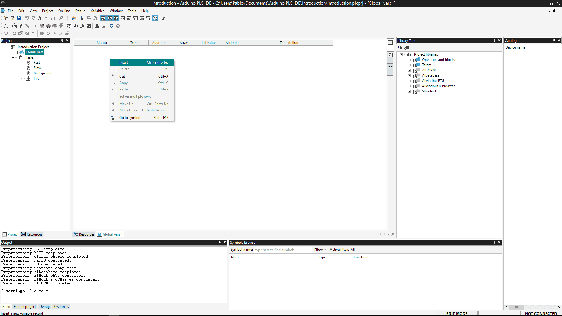
A dedicated "ladder for Arduino programmers" article can unpack contacts and coils. This session is only to prove the toolchain: license, runtime, port, one I/O pair.
If the IDE will not connect, Arduino's support article is the checklist: runtime install vs Modbus setup, which COM port, refresh target, disconnect extra USB-serial devices. Reinstalling Windows is not step one.
PLC IDE vs Arduino IDE 2
| Feature | Arduino IDE 2 | Arduino PLC IDE |
|---|---|---|
| Job | MCU sketches for makers and most boards | IEC 61131-3 plus sketches on industrial Arduino PLCs |
| Languages | Arduino C++ | Ladder, FBD, ST, SFC, IL, plus sketches |
| Timing model | setup() / loop() |
Scan cycle and cyclic tasks |
| Boards | Uno through ESP32 and far beyond | Opta, Portenta Machine Control |
| Operating system | Windows, macOS, Linux | Windows 10 64-bit+ only |
| License | IDE is free | IDE free; device license for IEC work |
| Fieldbuses | Libraries you write or install | Built-in Modbus / CANopen configurators |
A later comparison article can go longer. The table is enough to keep you from installing the wrong window.
Troubleshooting
| Symptom | Likely cause | Fix |
|---|---|---|
| Target will not activate | No device license, or wrong key | Follow the license tutorial for that SKU. Buy the key if you do not have one |
| Cannot connect after runtime install | Wrong COM port | Opta 1.3+: the single port. Machine Control: try the lower-numbered of the pair. Refresh current target |
| Two COM ports, IDE freezes on one | Machine Control's second port used as the Modbus target | Use the lower-numbered port for communication setup |
| You installed PLC IDE for an Uno | Wrong hardware class | Arduino IDE 2 |
| Mac / Linux, no installer | PLC IDE is Windows-only | Windows PC or a virtual machine |
| Sketch from IDE 2 "broke" PLC behavior | Two toolchains sharing flash without a partition plan | Read Arduino's memory partitioning guide, then reload the runtime from PLC IDE |
Wrap-up
Arduino PLC IDE is how Opta and Portenta Machine Control become PLCs in the IEC 61131-3 sense: scan cycle, ladder and Structured Text, Modbus and CAN, with room for an Arduino sketch next to that logic. It is a free Windows download with a paid device license. It is not Arduino IDE 2, and it is not for an Uno.
If your work is a breadboard and loop(), stay in IDE 2. If your work is a DIN rail and a panel drawing, this is the Arduino-shaped door into that shop.
Official docs: docs.arduino.cc/software/plc-ide. When menus move, trust that tree over a cached copy of this page.
Hack The World and Make Awesome.