Part 1 covered what Arduino is. Part 2 covered which board to buy. This part is where you start reading and writing software: how a sketch runs, the handful of functions you'll use on almost every build, how libraries work, and how to keep a sketch from running out of memory in a way that has nothing to do with your code being "wrong."
Have you ever copied a sketch from a tutorial, watched it work, and had no real idea why setup() and loop() were shaped that way? Or what half the functions in it did? That's what this article is for. Nothing here is exotic. It's just the vocabulary every later part of this series assumes you already have.
This part assumes an Uno or Nano for pin numbers, but everything here applies across the whole lineup from Part 2. There's no build at the end of this one. That's coming in Part 4, once these functions have something to actually do together. Think of this part as learning the words. Part 4 is the first sentence.
What Does a Complete Sketch Look Like?
Before we get into functions and libraries, I want to slow down and look at one complete sketch from top to bottom, because everything else in this article builds on its shape. A sketch is what Arduino calls a program. It is a plain text file, saved with the extension .ino, that you write in the Arduino IDE (the free app you use to type your code and send it to your board). Every sketch, from the simplest to the most complicated, is made of the same three parts: the globals and declarations at the top, the setup, and the loop. The easiest way to see all three at once is a sketch called Blink.
Blink is the "hello, world" of Arduino. It turns the LED that is built into your board on for one second, then off for one second, and repeats that until you unplug the board. You can find it in the Arduino IDE under File, then Examples, then 01.Basics, then Blink. The version below is the official one with a single change: I gave the LED's pin a name at the top, so you can see all three parts clearly. Read it once, and then we will take it apart one piece at a time.
// Blink: turns the board's built-in LED on for one second, then off for one second, forever.

const int ledPin = LED_BUILTIN;  // GLOBALS AND DECLARATIONS: give the built-in LED's pin a name; const means it never changes

void setup() {                   // THE SETUP: everything inside the braces runs once, at power-up or reset
  pinMode(ledPin, OUTPUT);       // tell the board this pin will send voltage out to the LED
}                                // end of setup()

void loop() {                    // THE LOOP: everything inside the braces runs over and over, forever
  digitalWrite(ledPin, HIGH);    // turn the LED on by putting voltage on the pin (HIGH)
  delay(1000);                   // pause for 1000 milliseconds, which is one second
  digitalWrite(ledPin, LOW);     // turn the LED off by taking the voltage away (LOW)
  delay(1000);                   // pause for another second, then loop() starts over at the top
}                                // end of loop()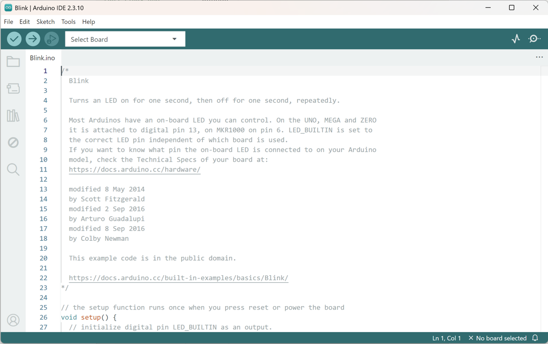
The Blink example open in the Arduino IDE 2. Screenshot: Arduino IDE.
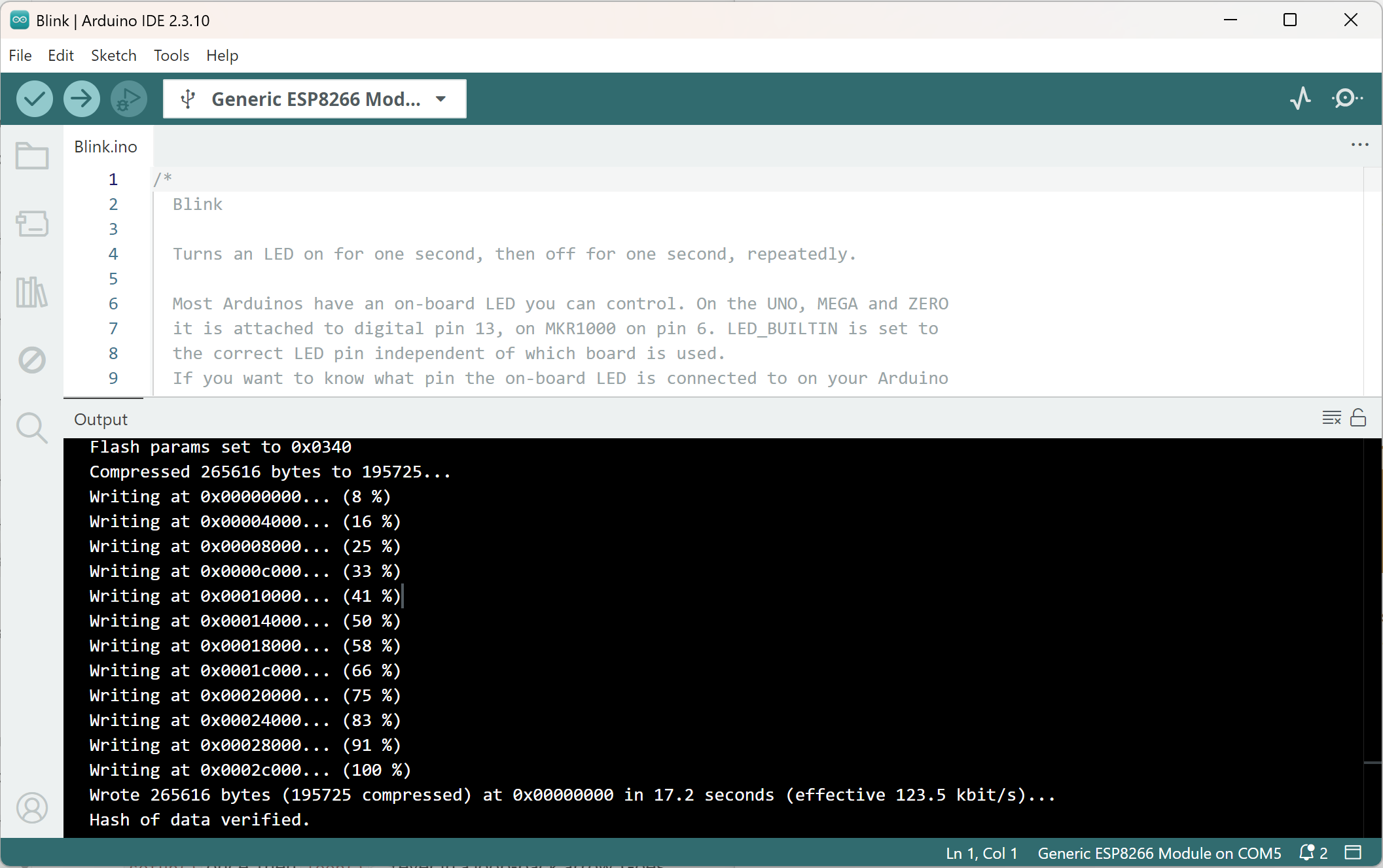
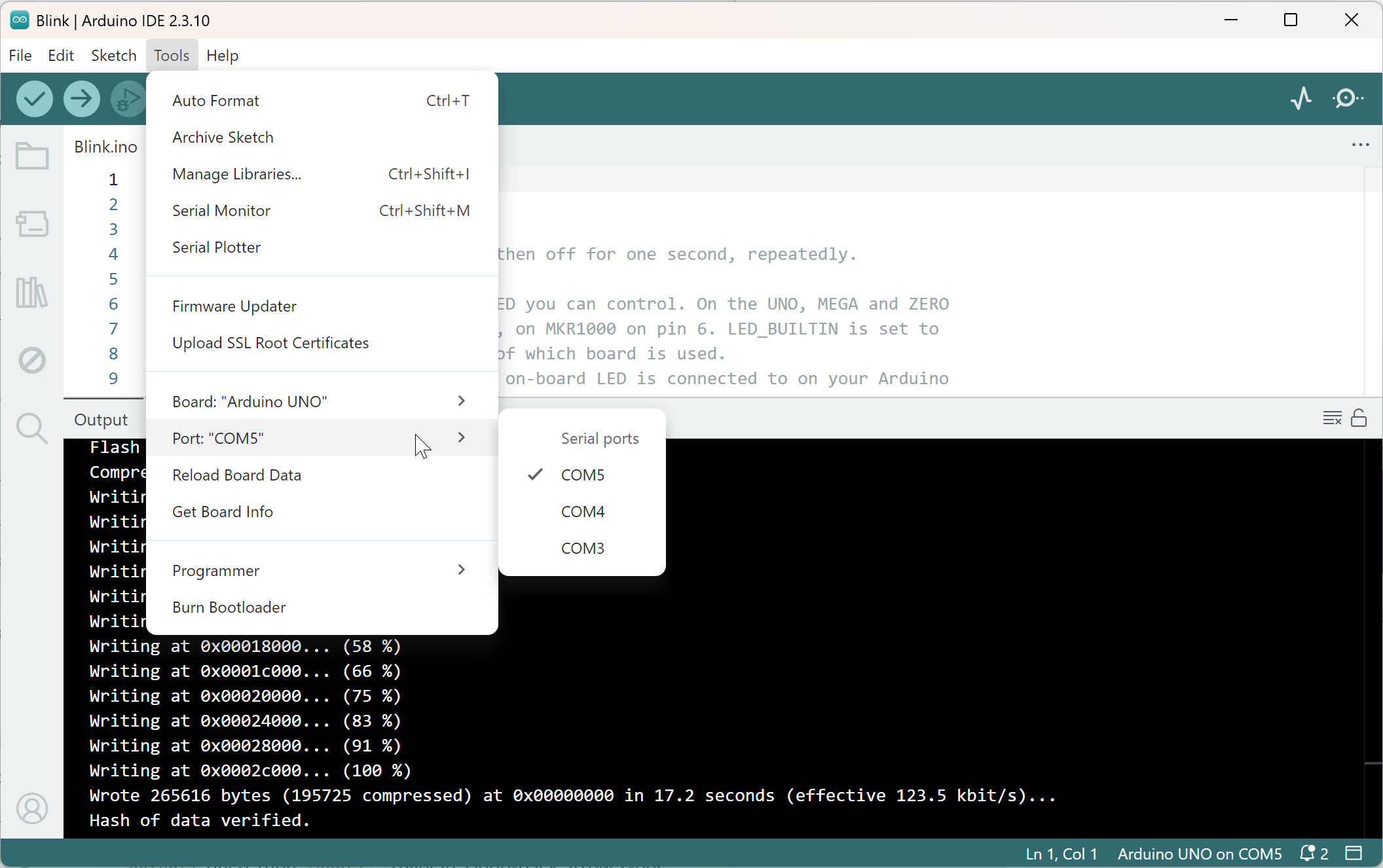
To run it on a real board, choose your board under Tools, then Board, and your port under Tools, then Port. Then click the Upload button (the right-pointing arrow at the top left). If you skip the board and port step, the IDE has no idea where to send the sketch, and that is the most common reason a first upload fails.
Globals and Declarations: The Top of the Sketch
The first part is everything that sits above setup(). This is where you put the things the whole sketch needs to know about before it starts running. In Blink, there is exactly one line here: const int ledPin = LED_BUILTIN;. Let me break that line into pieces, because every declaration you ever write follows the same pattern.
int is a data type, which tells the board what kind of value this is. An int is a whole number, like 13 or 1000. ledPin is a name I picked, and you can pick any name you like as long as it starts with a letter and has no spaces. LED_BUILTIN is a built-in value that Arduino fills in with the right pin number for whichever board you selected (it is pin 13 on an Uno). The word const is short for "constant," and it means the value is set once and never changes. The whole line is called a declaration, because it announces to the board that a name exists, what type of value it holds, and what that value starts as.
The word "global" matters here too. A name declared up at the top, outside of any function, is available everywhere in the sketch, so both setup() and loop() can use ledPin. A name declared inside a function is local, which means it only exists inside that one function. For now, just remember that the top of the sketch is for names that more than one part of the sketch needs.
Blink is small, so it only needs one line up here. In bigger sketches, this is also where you would put #include lines (which bring in libraries, covered later in this article), your other pin names, global variables that need to remember a value from one pass of loop() to the next, and any functions of your own that you want to declare before they are used. One gotcha is worth knowing now: almost every line in a sketch ends with a semicolon. Forgetting one is the number one reason a beginner's sketch refuses to compile, and the IDE's error message usually points to the line after the one that is actually missing it.
The Setup: What Runs Once
Next comes void setup(). Here is what each piece means. void says the function does not hand any value back when it finishes. setup is its name, and Arduino looks for exactly that name. The empty parentheses () are where inputs would go, and this function takes none. The curly braces { } wrap every line that belongs to the function, the same way a pair of brackets wraps a sentence.
Everything inside the braces runs one time, either when the board first gets power or when you press its reset button. Think of it as the "get ready" stage. In Blink, there is a single job: pinMode(ledPin, OUTPUT);. That line tells the board that the LED's pin will be an output, which means it will send voltage out to something instead of listening for a signal coming in. Later in this series, setup() is also where you open the Serial connection and start up sensors, which are all things that only need to happen once.
The Loop: What Runs Forever
The last part is void loop(), which has the same shape as setup(). The difference is in how often it runs. The lines inside it run from top to bottom, and when the board reaches the closing brace, it jumps right back to the top and runs them again, forever, for as long as it has power. This is where the real work of your sketch happens.
Blink's loop has four lines. digitalWrite(ledPin, HIGH); puts voltage on the pin, which turns the LED on. delay(1000); makes the board wait for 1000 milliseconds (a millisecond is a thousandth of a second, so that is one second). digitalWrite(ledPin, LOW); takes the voltage away, and the LED goes dark. Then another delay(1000); waits a second, and the whole thing starts over. On, wait, off, wait, repeat. That is all Blink does, and it is also the shape of almost every sketch you will write.
Putting the Three Parts Together
If you take one thing away from this section, make it this. The top of the sketch is for names and settings that the whole sketch shares. The setup is for getting ready, and it runs once. The loop is for doing the work, and it runs forever. When you open a sketch somebody else wrote, even a long one, you can find these three parts and read it in that order.
Here is a quick way to make it stick. Upload Blink, then change both 1000 values to 250 and upload it again. The LED should blink four times as fast. Then try changing only the first delay() to 100 and leaving the second at 1000, and watch how the pattern changes from an even blink to a quick flash with a long pause. If the LED does nothing at all, check the board and port settings from earlier before you suspect the code.
The next section looks at what is happening underneath setup() and loop(), including a function you never write that starts everything off.
How Does a Sketch Actually Run?
Every Arduino sketch you write has the same two functions. setup() runs exactly once. loop() runs over and over, forever, for as long as the board has power. That's the whole structure. No matter how complicated a project gets later in this series, it still comes down to those two functions.
Most beginner tutorials skip something worth knowing: you never actually write the function that starts your program. Somewhere deep inside the Arduino core, in files you'll never open, there's a real function called main(). It's the true starting point of your program, the same way main() is the starting point of every C or C++ program ever written, on any computer. Arduino writes that main() for you and hides it, specifically so you never have to think about it. You only ever write setup() and loop().
If you're curious what it actually looks like, here it is, simplified down to the important parts:
int main(void) {
  init();          // turns on the board's clocks, timers, and ADC
  initVariant();   // extra board-specific setup some boards need
  setup();          // your setup() - runs once
  for (;;) {         // an endless loop, never exits
    loop();           // your loop() - runs again, and again, forever
  }
  return 0;   // never actually reached: the for(;;) loop above never exits
}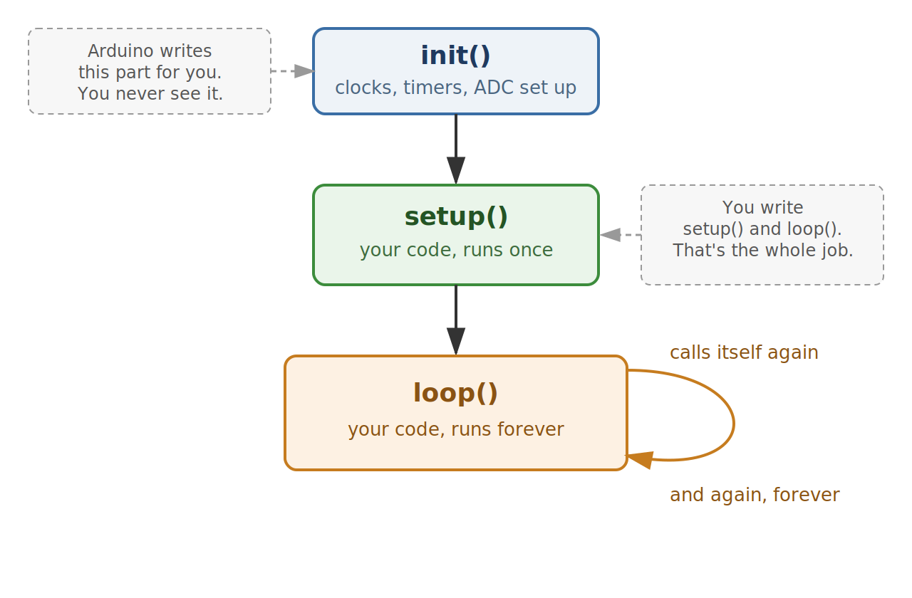
Don't worry about memorizing that. You'll never write it yourself. But there's one thing worth taking away from it. There's no operating system running your sketch, and no way for your Arduino to genuinely do two things at once, the way your phone or laptop can. There's just that one loop, running forever. Whatever single line loop() happens to be sitting on right now is the only thing your Arduino is doing. That's it. Hold onto that. It matters a lot in Part 4.
One more thing init() does before your code ever runs: it starts a hardware clock ticking in the background. That clock keeps going the entire time your sketch runs, completely separate from whatever setup() and loop() are doing. You're not using it yet. Part 4 is built entirely around it.
Organizing Your Sketch
Two small habits pay off almost immediately once your sketches start getting longer.
First: name every pin you use exactly once, right at the top of the sketch, using the keyword const (short for "constant," meaning the value gets set once and never changes for the rest of the program). Say you rewire your project to a different pin later. If you named the pin once at the top, you change one line. If you didn't, you're hunting through your whole sketch for every place you typed 13, hoping you didn't miss one.
Second habit: don't cram everything into loop(). Write small functions instead. Give each one a name that says exactly what it does, and just call them from loop(). Your loop() ends up reading like a short list, do this, then this, then this, instead of a wall of logic you have to read top to bottom just to figure out what's actually happening.
Here's a small sketch that follows both habits. Load it up if you have a board handy, and let's walk through it together:
const uint8_t LED_PIN = 13;  // onboard LED
const uint8_t BTN_PIN = 2;   // pushbutton

void setup() {
  pinMode(LED_PIN, OUTPUT);        // we're driving the LED
  pinMode(BTN_PIN, INPUT_PULLUP);  // we're reading the button
  Serial.begin(9600);              // open the Serial connection so we can print
}

void loop() {
  blinkOnce();     // job 1: blink the LED
  reportButton();  // job 2: check the button
}

void blinkOnce() {
  digitalWrite(LED_PIN, HIGH);  // LED on
  delay(500);                   // wait half a second
  digitalWrite(LED_PIN, LOW);   // LED off
  delay(500);                   // wait another half second
}

void reportButton() {
  bool pressed = digitalRead(BTN_PIN) == LOW; // INPUT_PULLUP: pressed = LOW
  Serial.println(pressed ? F("pressed") : F("released"));
}
We start by naming our two pins, LED_PIN and BTN_PIN, right at the top with const, exactly like we just talked about.
In setup() we set the LED pin to OUTPUT, the button pin to INPUT_PULLUP, and open the Serial connection at 9600 baud. All three of those only need to happen once, which is why they live in setup() and nowhere else.
Now on to loop(). Notice it's only two lines: it calls blinkOnce(), then it calls reportButton(). That's the whole thing. You can read what this sketch does without even looking at the two functions underneath it.
blinkOnce() turns the LED on, waits half a second, turns it off, waits another half second. reportButton() checks the button and prints whether it's pressed or released out to the Serial Monitor. Then loop() starts over, and it does it all again.
Go ahead and watch the button while this is running. Here's the catch: it only gets checked once a second, right after the blink finishes its cycle, because delay() freezes everything else while it's waiting. Serial, the button, everything just stops. That freeze is the problem Part 4 exists to fix.
For right now, don't worry about the timing. Just notice the shape: name your pins once, give each job its own small function, let loop() call them in order.
Core Functions You'll Use Constantly
pinMode(): Telling a Pin What It's For
Every pin needs to be told, in setup(), whether it's an INPUT (reading a signal from something, like a button) or an OUTPUT (sending a signal to something, like an LED). That's the whole job of pinMode().
Almost every beginner falls into this trap once. Set a pin to plain INPUT and leave nothing solidly connected to it, and it won't reliably read HIGH or LOW at all. It "floats." It picks up tiny stray electrical noise from the air around it, almost like an antenna, and reports random, meaningless flickering even when nothing is touching it.
This is exactly why INPUT_PULLUP exists. It switches on a small resistor built right into the chip that gently holds the pin at a steady HIGH by default. Wire a button between that pin and ground, and pressing the button firmly pulls the pin LOW. Let go, and it firmly returns to HIGH. No floating. No noise. No mystery flickering.
OUTPUT is simpler. It just lets you drive the pin yourself, pushing it HIGH (about 5 volts on a classic Uno, 3.3 on some newer boards) or LOW (0 volts).
One habit worth keeping for life: always set a pin's mode in setup(), before you ever try to read from or write to it. Every pin defaults back to INPUT on every reset, until your code says otherwise.
Incidentally, you'll sometimes see projects wire in a physical pull-down resistor instead of using INPUT_PULLUP. Both solve the same floating-pin problem. I'd rather you use INPUT_PULLUP whenever you can. It's one less part to buy, one less thing to wire wrong, and it's already sitting there inside the chip waiting to be turned on.
digitalRead() and digitalWrite(): Reading and Setting a Pin
These are how you use a pin once its mode is set. digitalWrite(pin, HIGH) turns a pin on. digitalWrite(pin, LOW) turns it off. digitalRead(pin) checks whether a pin is currently HIGH or LOW and hands that answer back to your code. That's really it. For almost everything you'll build in this series, these two functions are all you need.
analogRead(): Reading More Than Just On or Off
digitalRead() only ever gives you two possible answers, HIGH or LOW. But plenty of real signals aren't on-or-off. Turn a potentiometer (that's just a knob) and its output can sit anywhere between fully low and fully high. A light sensor reports a whole range of brightness, not just "light" or "dark." Reading one of those needs analogRead() instead.
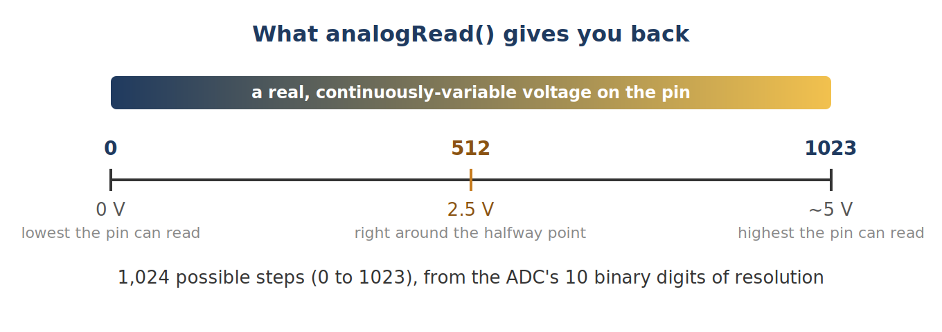
Here's the number worth remembering: on a classic Uno or Nano, analogRead() hands you back a number from 0 to 1023. That's 1,024 possible steps. Where does that number come from? A tiny piece of hardware inside your Arduino called the ADC, short for analog-to-digital converter. It measures a real, continuously-variable voltage and reports back the closest number it can represent using 10 binary digits. 0 means "as low a voltage as this pin can measure." 1023 means "as high a voltage as this pin can measure," usually right around the board's own 5-volt supply. A pin sitting at exactly half that, 2.5 volts, reads back very close to 512, right around the halfway point.
Quick heads up: by default, that "top end" of 1023 always means the board's own power supply. You can change what it means with analogReference(), but leave that alone until you actually need it. One easy way to damage a pin permanently is feeding a voltage into the AREF pin before your code has told the board, with analogReference(), that it should expect one.
analogWrite(): Simulating Analog Output with PWM
Your Arduino's pins can only ever be fully HIGH or fully LOW. So how does analogWrite() make an LED look dimmer, or a motor seem to spin slower, instead of just snapping fully on or off?
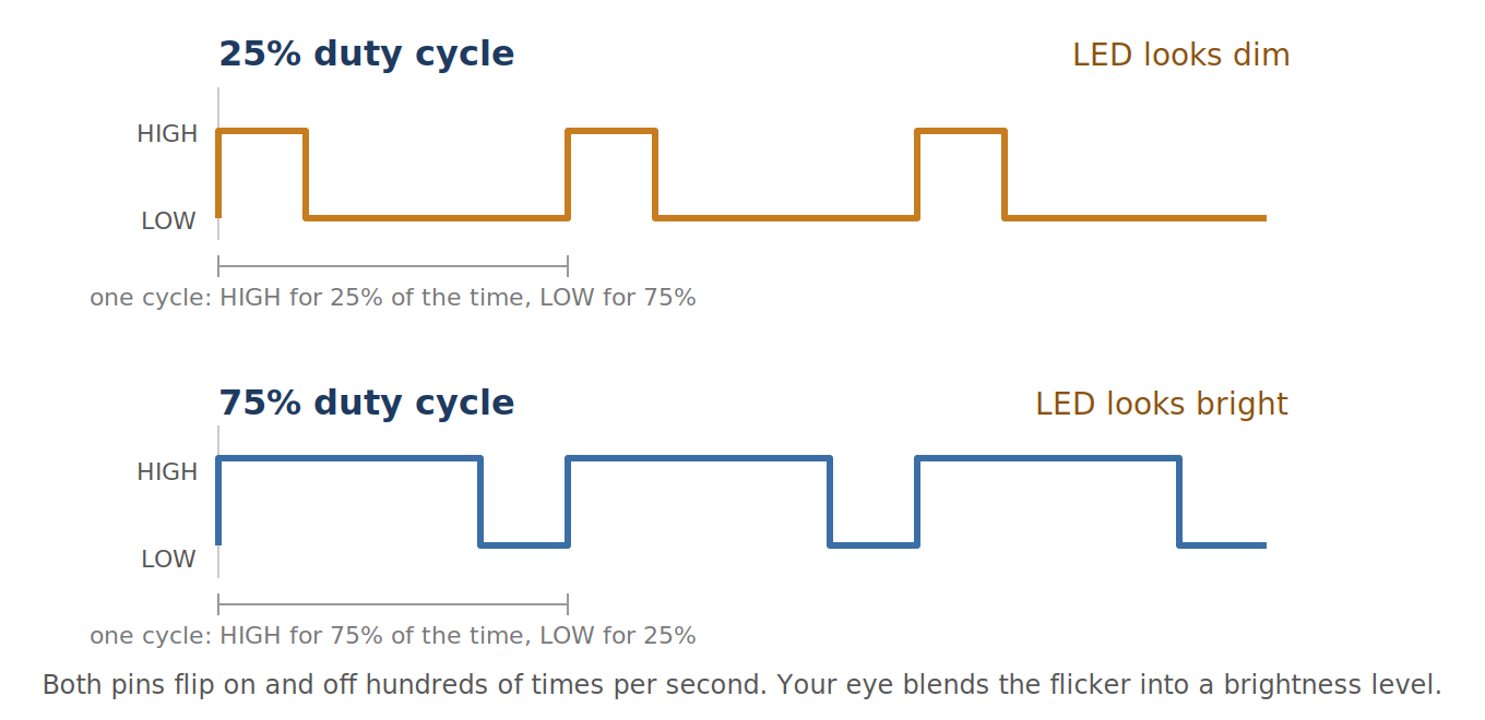
It's a trick. There's no real in-between voltage happening. The pin flips on and off very fast, somewhere around 500 to 1,000 times a second, and analogWrite() controls what fraction of that time it spends HIGH versus LOW. That fraction has a name: duty cycle. Set a pin to flip on for 25% of each cycle and off for the other 75%, and an LED wired to it looks dim. At any single instant it's still either fully lit or fully dark. Your eye just can't keep up with the flickering, and it blends into "dim." A motor responds to the same trick, though for a slightly different reason. More on that when we get to motors later in the series.
This trick only works on certain pins, too. On an Uno or Nano, that's just the ones marked with a ~ next to the number, right on the board itself: pins ~3, ~5, ~6, ~9, ~10, ~11. Call analogWrite() on a pin without a ~, and here's the annoying part: you won't get an error. You'll just silently get plain HIGH or LOW back, no dimming at all. That's a confusing bug to chase down if you don't already know to check for it. Now you do.
analogWrite(pin, 128) sets a duty cycle of 128 out of 255, just about half. If you actually need real, steady analog voltage, a true 2.5 volts and not a fast-flickering approximation of it, that needs different hardware entirely, called a DAC (digital-to-analog converter, the reverse of the ADC from a minute ago). Most classic Arduino boards don't have one built in at all.
map() and constrain(): Relabeling a Range of Numbers
Numbers coming out of analogRead() are stuck in that 0-1023 range, and that's rarely the range you actually want. Say you're reading a potentiometer that's meant to represent a percentage. You want 0 to 100, not 0 to 1023. That's what map() is for:
int raw = analogRead(A0);                 // 0..1023
int pct = map(raw, 0, 1023, 0, 100);      // 0..100
pct = constrain(pct, 0, 100);             // clamp it, in case map() ever overshoots
map() is just proportional math. It doesn't add precision you didn't already have. It only relabels the same 1,024 possible readings onto a different scale. And because it's just math, it's entirely possible to feed it a number slightly outside the range you told it to expect, and get back a result outside the range you wanted. So wrap the result in constrain() any time it's about to drive something sensitive, like a PWM pin or a servo. That way a stray out-of-range number can never send that pin somewhere it shouldn't go.
Serial: Your Best Debugging Tool
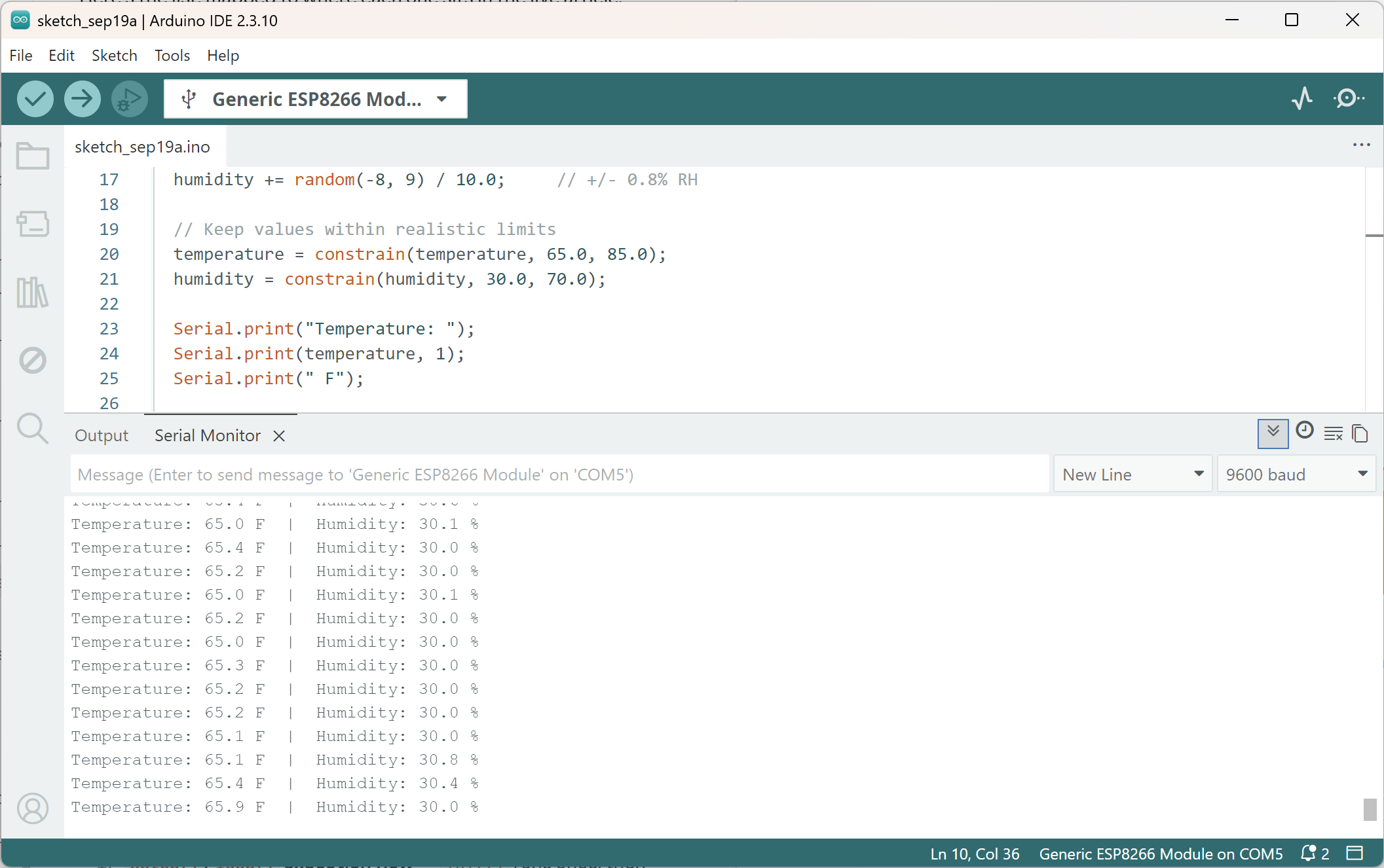
Serial.begin(9600) opens up a channel between your Arduino and your computer, over the very same USB cable you used to upload the sketch. Once it's open, your code can send text back to you while it's running. This is, hands down, the single most useful thing you have as a beginner. Instead of guessing what your program is doing, you can just have it tell you.
That number, 9600, is called the baud rate: how fast the two sides have agreed to talk, measured in bits per second. Both ends have to agree on the exact same number, or all you'll see in the Serial Monitor is garbled symbols instead of readable text. Use 9600 while you're learning. Once you're past "hello world," bump it up to 115200. Less time spent transmitting text is more time your loop() gets to spend doing everything else.
void setup() {
  Serial.begin(115200);  // open the connection at 115200 baud
  // Native-USB boards only (Leonardo, Micro, some SAMD):
  // while (!Serial) { ; }
}

void loop() {
  int v = analogRead(A0);       // read the pin, 0-1023
  Serial.print(F("A0="));       // label so the number makes sense on its own
  Serial.println(v);            // print the reading, then a line break
  delay(200);                   // just to keep the printing readable for this demo
}
Notice the F() wrapped around the text there? That keeps the string sitting in flash memory instead of copying it into SRAM, a small, fast, easy-to-fill pocket of working memory your sketch leans on while it runs. We'll dig into that properly in a minute. For now, just know an Uno only has 2 KB of it total, and it fills up faster than you'd guess. Get in the habit of using F() on AVR boards (Uno, Nano, Mega) from day one.
One rule worth knowing even before you fully understand why: don't call Serial.print() from inside an interrupt. An interrupt is a special kind of function that briefly pauses whatever your code is doing to react to something urgent. You'll meet these properly in a later article. Sending serial data is relatively slow, and leans on interrupts of its own behind the scenes, so calling it from inside one can jam things up in ways that are genuinely hard to debug. If you ever do write an interrupt, set a flag inside it, and do your actual Serial.print() from loop() instead.
One more thing, specific to certain boards: on Leonardo and Micro, USB is handled by the main chip itself, not a separate helper chip like on the Uno. That's why you'll sometimes see while (!Serial) { ; } in setup(). It waits until your computer actually opens the Serial Monitor before continuing, and on those boards, that's correct. Put that same line on an Uno or Nano, though, and your sketch just hangs forever in setup(), waiting for something that will never happen. Those boards don't work that way, so skip that line entirely if you're using one.
What's a Library, and Why Do You Need One?
A sensor doesn't send your Arduino the word "23.5 degrees." It sends raw electrical pulses that, on their own, mean absolutely nothing. Your Arduino has no built-in idea what those pulses represent. Something has to translate those pulses into a number you can actually use, like temperature = 23.5.
That something is a library: a piece of code someone else already wrote and shared, that knows how to talk to one specific sensor or module. Without one, you'd need to read that sensor's datasheet cover to cover and write the translation yourself, often down to individual bits. People do that. Almost nobody does it for a hobby project, and you don't have to either. You use someone else's library instead, and get on with actually building your project.
Some libraries, Wire.h, SPI.h, Servo.h, already ship with the Arduino IDE. You can #include those right now, no installing required. Most sensor and display libraries don't come built in, though, and have to be installed once before you can use them.
Installing a Library the Easy Way
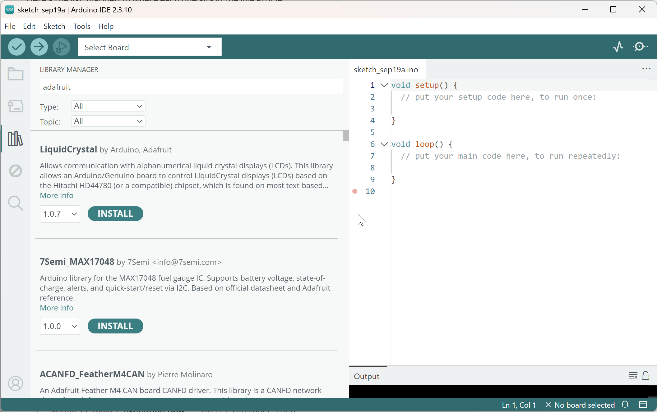
- Open the Arduino IDE, and go to Tools → Manage Libraries (or press Ctrl+Shift+I). A search panel opens up.
- Type the library's name. If you get several results for the same sensor, pick the one published by the actual manufacturer, usually Adafruit or SparkFun, or by Arduino itself.
- Click Install. That's it. A copy of the library is saved on your computer, inside the IDE, ready to use in any sketch you write from now on.
- At the top of your sketch, add a line like
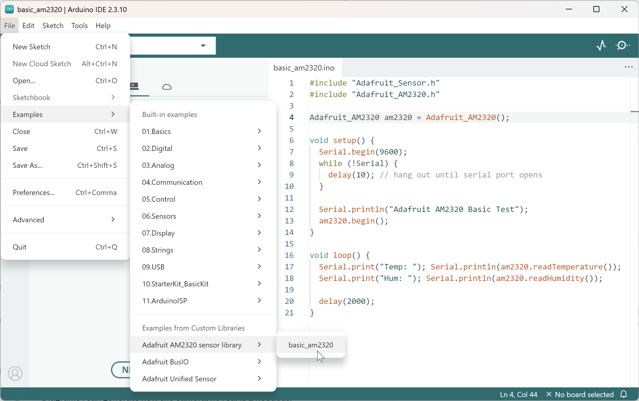
#include <LibraryName.h>. This tells the compiler "pull in that library's code before you build this sketch." - Once a library's installed, go check File → Examples → {library name}. Working example code almost always shows up there, and it's a great way to confirm everything installed correctly before you write a single line of your own.
Installing a Library You Downloaded Yourself
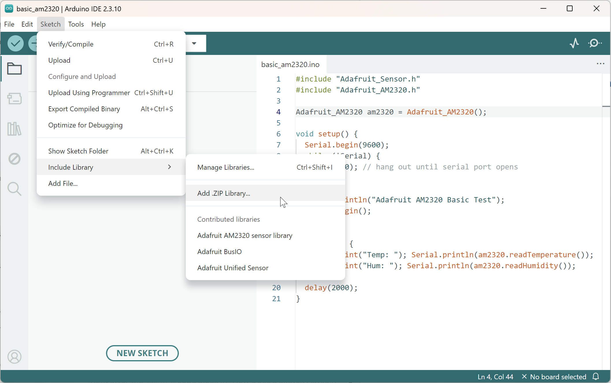
Not every library shows up in that search panel. Plenty of tutorials, including some right here on this site, will point you to a GitHub page instead, where you download a .zip file directly. Here's how you install one of those: Sketch → Include Library → Add .ZIP Library…, then pick the file you just downloaded. The IDE unpacks it and installs it exactly the same as if it had come straight from the Library Manager. The only real difference is you're pointing the IDE at the file yourself, instead of letting it search for you.
Boards Manager Is Not the Library Manager
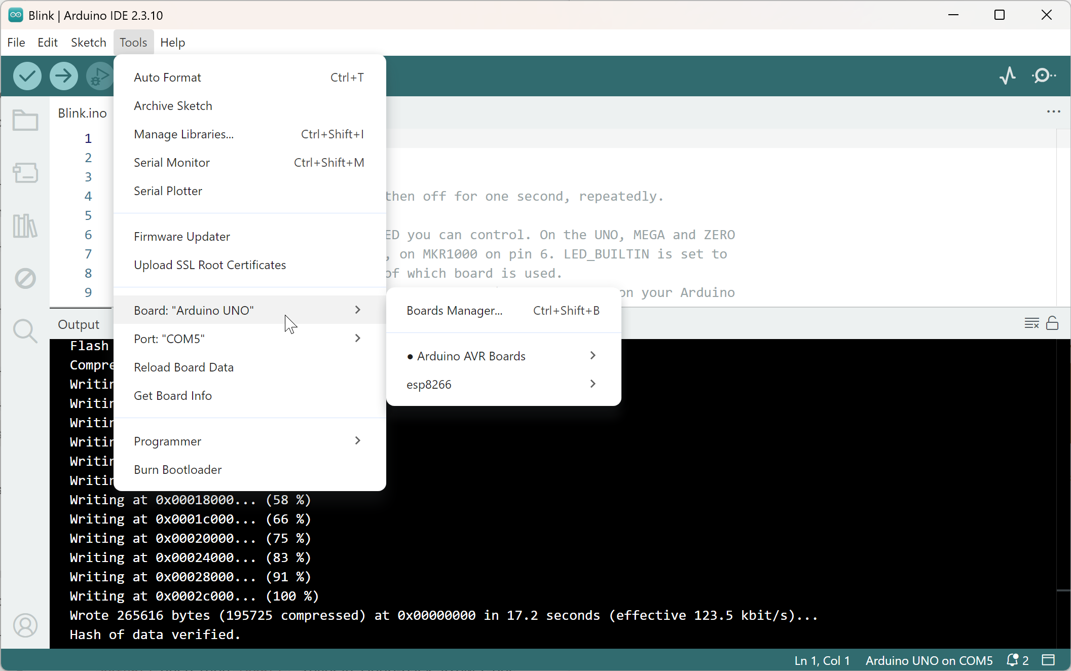
One more distinction worth knowing about now, even though it is not this article's main topic: if you ever use a board outside the classic AVR family (an ESP32 or ESP8266, for instance), you need to install a board package before that board even shows up in the Boards menu. That is a different thing entirely from a library, and it trips people up because both get installed through similar-looking menus.
A library teaches your sketch how to talk to one sensor or module. A board package teaches the Arduino IDE itself how to compile and upload code for a whole different chip. You install a board package once, through File → Preferences, by pasting a URL into the "Additional Boards Manager URLs" field. Each board family publishes its own URL; the ESP8266 core's is a common one to see in tutorials. Then open Tools → Board → Boards Manager, search for the board family by name, and click Install.
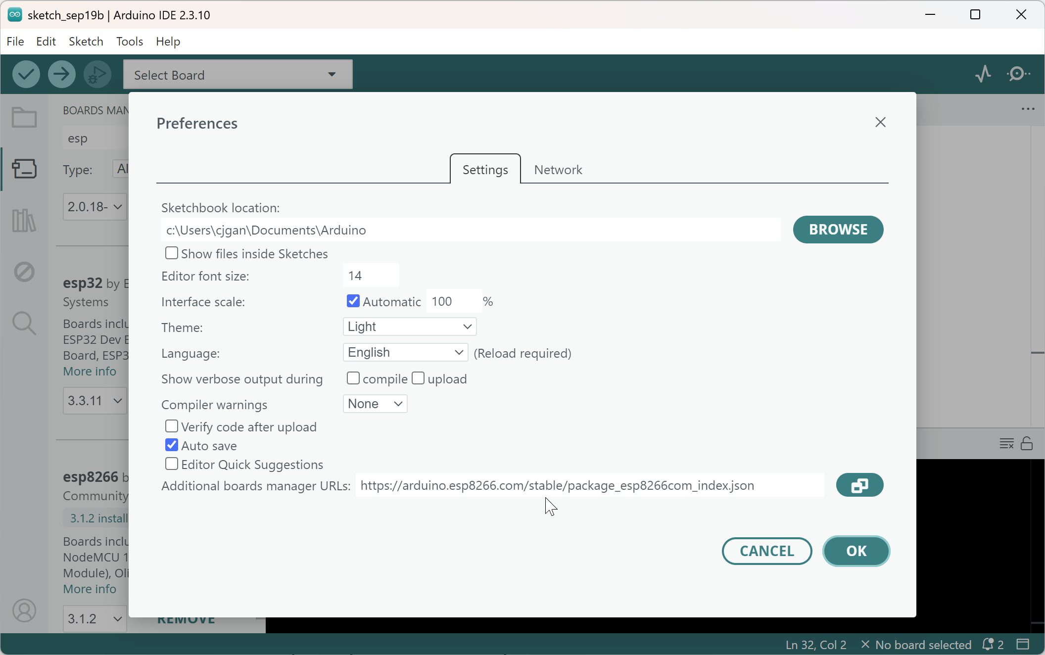
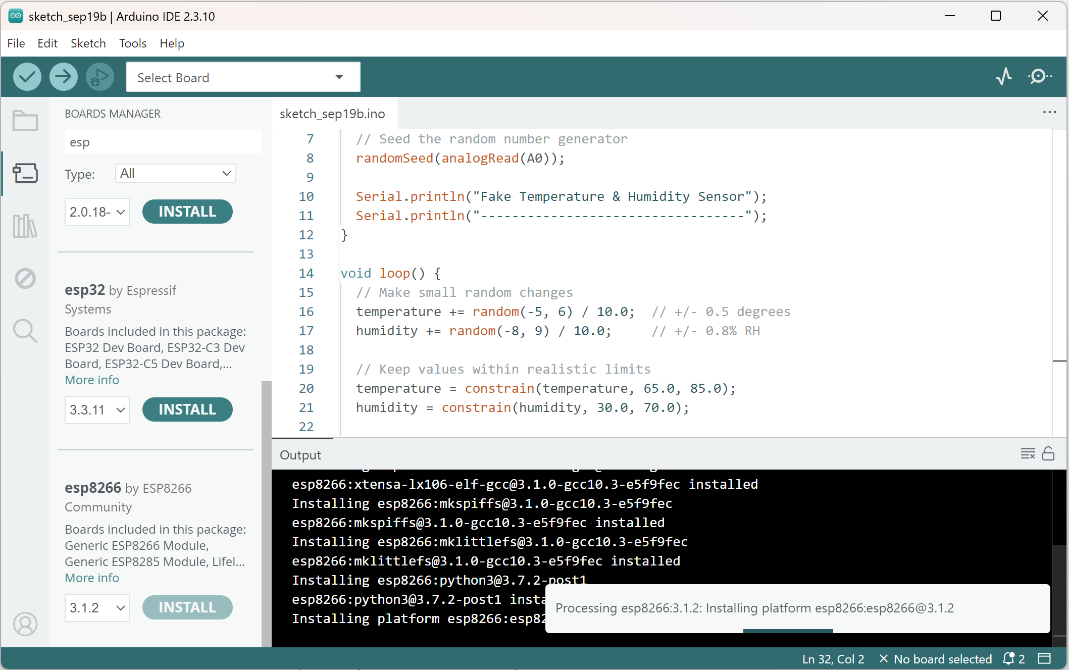
Part 2 covered choosing a board. This is the one-time setup step that makes a non-Uno board actually usable in the IDE. You will not need any of this if you are following along on an Uno or Nano. Every board in that family already works out of the box.
When Two Libraries Share the Same Name
This trips up a lot of people, and it isn't really a beginner mistake. It happens to experienced folks too. Two completely different libraries can use the exact same name for the thing you're trying to control.
Say you're following a tutorial, and your code either won't compile, or it compiles fine but nothing matches what the tutorial shows on screen. Before you assume you made a typo somewhere, check this first: did you install a different library with the same name as the one the tutorial actually used?
Here's a real example. Several different libraries out there all call themselves LiquidCrystal_I2C, and they're all used for controlling a common type of LCD screen. If a tutorial's code calls lcd.init(), and the version you installed only has lcd.begin(), or the other way around, that's not a bug in your code. You just have a different fork of the library than whoever wrote the tutorial. The fix isn't to keep debugging code that was never actually broken. It's to go find and install the exact library the tutorial used. Our own DHT22 + LCD project uses the Frank de Brabander version of LiquidCrystal_I2C specifically, so if you ever build that project and your LCD calls don't match what's shown, that's why.
A Few Library Names You'll See Often
You don't need to know yet what I²C, SPI, or EEPROM actually are. Each one gets a full part of its own later in this series. For now, just recognize the names when you see them in a tutorial's #include line, so you know they're expected, not a mistake:
Wire.h: used any time a project talks over I²C, a two-wire connection a lot of sensors and displays use. Comes with the IDE already. Full explanation: Mastering I²C.SPI.h: a faster, four-wire connection, common on SD cards and some displays. Also already in the IDE. Full explanation: Mastering SPI.EEPROM.h: used to save small bits of data, like a setting, that survive even after your Arduino loses power.
One last thing worth knowing now, so it doesn't confuse you down the road: if you ever switch to PlatformIO instead of the Arduino IDE, each of your projects gets its own separate copy of every library, instead of one shared copy for everything the way the IDE's Library Manager works. That's why two different PlatformIO projects can disagree about "which version" of a library they're using. They're each allowed their own, and that's normal, not a bug.
Why Might Your Sketch Run Out of Memory?
Your Arduino has two completely different kinds of memory, and mixing up what belongs in which one is one of the more common reasons a sketch that "should" work does something bizarre instead. It hangs. It resets itself for no obvious reason. A display shows garbage. And the compiler never warns you, because as far as it's concerned, nothing is wrong.
Flash memory is where your actual compiled program lives. Picture a filing cabinet: big, 32 KB on an Uno, but slow to get into, and it only changes when you upload new code. SRAM is a completely different thing. Picture your actual desk surface while you're working: much smaller, just 2 KB on an Uno, but instant to read and write. Every variable in your running sketch lives there while your code is actually executing. The second power is lost, everything on that desk is wiped clean instantly. That's why SRAM is the wrong place to store anything you need to survive a reset. That's what EEPROM, mentioned a minute ago, is actually for.
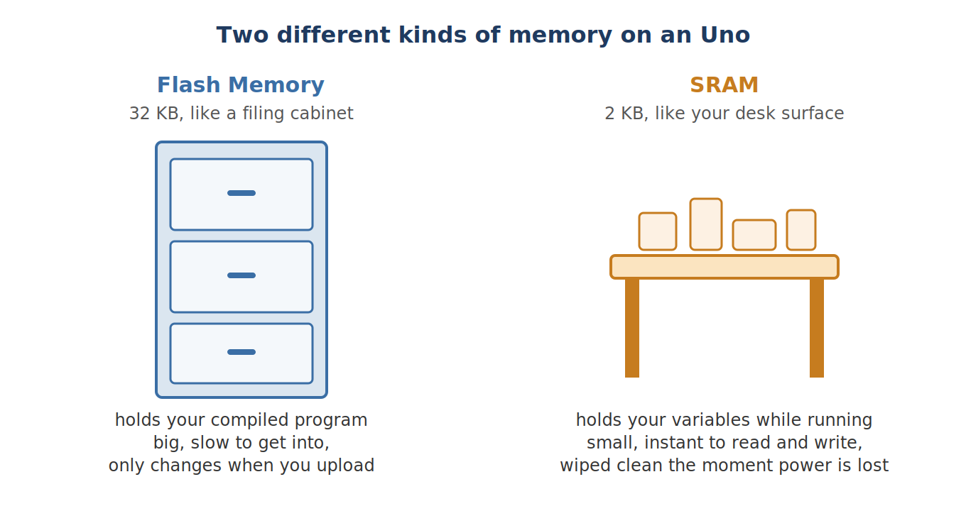
2 KB sounds like plenty, until you start adding things up. A single line like char debug[200]; claims 200 of your 2,048 bytes, permanently, for as long as your sketch runs, whether you're actually using all 200 characters or not. Add a few lines like that. Mix in Arduino's built-in String type doing repeated concatenation, which quietly reallocates memory behind the scenes every single time a string grows. Throw an SD card library on top. Now you can run out of desk space without a single compile error ever warning you it was coming.
So what does running out actually look like? A sketch that suddenly hangs the moment you add one more Serial.println. An OLED display that reports "failed to initialize," even though your wiring is completely fine. A function that quietly returns a garbage number that makes no sense at all. None of these come with an obvious "you're out of memory" message. That's what makes this so frustrating the first time it happens to you, so it's worth knowing about now, before you're the one staring at a display that just won't turn on.
Good news: the Arduino IDE actually tells you how close you're cutting it, every single time you compile. Look right after a successful compile for a line that says something like "Global variables use X bytes of dynamic memory." Leaving a few hundred bytes of headroom is a good habit on any Uno-class board. Three things help. Wrap text you print in F(), like we covered in the Serial section, so it stays in flash instead of copying into SRAM. Use const lookup tables stored in PROGMEM, which is just a way of telling the compiler "leave this sitting in flash permanently, don't copy it into SRAM," instead of big arrays that live in SRAM. And prefer plain character arrays over Arduino's String type on Uno-class boards, since String's automatic memory juggling is exactly the kind of thing that quietly eats your 2 KB out from under you. Personally, I still reach for String on quick one-off tests where I don't care about the last few bytes, just not in anything that's supposed to run for hours unattended.
A Basic Debugging Checklist
Here's the exact routine I run through, in order, any time something isn't working and I don't yet know why:
- Double-check the board and port are actually right in the IDE. This sounds too obvious to write down, but "wrong core selected, right USB chip plugged in" gives you a confident "upload done" message and a sketch that never behaves the way you expect, because it isn't actually the sketch you think it is.
- Blink the onboard LED from the simplest two-line sketch you can write. If that works, power and the upload path are both fine, and whatever's wrong lives somewhere else.
- Print a unique boot message from
setup(), something likeSerial.println(F("BOOT OK"));, so you always know for certain whether a reset actually happened, instead of guessing. - Add one new part at a time. Test it before moving on to the next one. Running the I²C scanner before calling any sensor library's
begin()is part of this same habit: confirm the device actually shows up on the bus before you start assuming the library itself is broken. - If a sketch feels sluggish or unresponsive and you can't explain why, search it for
delay(. Part 4 covers exactly what to do instead. But even before you've read that, "there's a hiddendelay()somewhere" turns out to be the answer more often than not.
Where This Fits in the Series
You now have the vocabulary that Part 2's hardware actually needs: a real mental model of how a sketch runs, the core functions you'll reach for constantly, Serial as a debugging tool, libraries, and an eye on your memory budget. Nothing here has a stopwatch attached to it yet. That's on purpose, and it's coming next.
- Part 1: What is Arduino
- Part 2: Choosing the right board
- DHT22 temperature and humidity, a real library, a real sensor, put to work
- Mastering I²C, Wire, addressing, BME280 and OLED
- External interrupts, for when a pin event can't wait for
loop()
Wrap-Up and What's Next
setup() and loop() aren't a toy structure. They're the entire scheduler you get, and now you know what's running underneath them. Core functions are thin wrappers around real hardware, not magic incantations to copy and paste without understanding. Libraries save you from rewriting a datasheet from scratch every time you touch a new sensor. SRAM is a budget you didn't know you had, until the day you blow right through it.
You've probably noticed every single example on this page still leans on delay(). That was on purpose. This part is vocabulary, not timing, not yet. Next up, Part 4: you throw delay() out for good, meet millis(), and build the first real project in this series. A control panel that blinks an LED, reads a potentiometer, and watches a button, all at the same time, with none of them ever blocking each other.
Want to go deeper? Download the full eBook once the series is complete, and subscribe for the rest of the Arduino Mastery Series.
Hack The World and Make Awesome.